ANIMATION STRATEGIES FOR SMOOTH TRANSFORMATIONS
BETWEEN DISCRETE LODS OF 3D BUILDING MODELS
Martin Kada a, *, Andreas Wichmann a, Yevgeniya Filippovska a, Tobias Hermes
a Institute of Geodesy and Geoinformation Science (IGG), Technische Universität Berlin,
Straße des 17. Juni 135, 10623 Berlin, Germany [email protected]
Commission II, WG II/6
KEY WORDS: Building, 3D, Multiple Representations, Animation, Levels of Detail, Visualization
ABSTRACT:
The cartographic 3D visualization of urban areas has experienced tremendous progress over the last years. An increasing number of applications operate interactively in real-time and thus require advanced techniques to improve the quality and time response of dynamic scenes. The main focus of this article concentrates on the discussion of strategies for smooth transformation between two discrete levels of detail (LOD) of 3D building models that are represented as restricted triangle meshes. Because the operation order determines the geometrical and topological properties of the transformation process as well as its visual perception by a human viewer, three different strategies are proposed and subsequently analyzed. The simplest one orders transformation operations by the length of the edges to be collapsed, while the other two strategies introduce a general transformation direction in the form of a moving plane. This plane either pushes the nodes that need to be removed, e.g. during the transformation of a detailed LOD model to a coarser one, towards the main building body, or triggers the edge collapse operations used as transformation paths for the cartographic generalization.
* Corresponding author
1. INTRODUCTION
The main difficulties of real-time 3D visualization systems are to efficiently transmit complex scenes over computer networks with insufficient transmission speed and to make best use of the available rendering capacity. So the amount and complexity of the displayed data have to be properly adjusted. A common technique is thereby to have different levels of detail (LOD) for one and the same object and interchange them depending on the overall technical necessity or its context, e.g., in a cartographically generalized and compiled scene. When using discrete LODs, as e.g. defined by the CityGML standard, a sudden replacement of an object’s geometric representation can be distracting and disturbs users in their spatial and environmental immersion. To avoid this so-called pop-up effect, many strategies have been proposed, particularly in the field of mesh simplification and terrain rendering (Luebke et al., 2003), to perform continuous geometrical and topological transformations of the object’s representation. However, these methods do not consider specific cartographic characteristics of 3D building models (e.g. rectangular and symmetrical shapes). Consequently, those characteristics are often violated, which leads to major distortions of 3D building models during their geometric transformation and makes them visually unpleasing or even unrecognizable at their intermediate steps. This hinders the efficient perception of the displayed state of a 3D scene during the transmission process.
As the theory of recognition by components states, objects are recognized as configurations of simple, primitive volumes called geons, which are interconnected with each other in a specified way so that an object can be recognized even from different points of view (Hummel and Biederman, 1992). Thus,
the preservation of these relations and proper communication of changes in the structure and appearance of an object plays a key role for the organization and maintenance of a human viewer’s mental map. Graphs can be considered as a common way to visualize relational data. In this connection, the work in (Nesbitt and Friedrich, 2002) examines, e.g., how Gestalt principles can be applied when creating graph animations in order to make them comprehensible. Ware (2004) also discussed how sensitive human perception is to patterns in motion. The gradual alteration of an object’s shape by means of a continues movement of its individual parts represents a proper way to preserve the correspondence between different representations of an object. Thus leading to a comprehensible visualization of its transformation.
To further improve the edge-collapse ordering towards a more intuitive animation of the transformation process, a weighting strategy is incorporated that considers both length and orientation of edges as well as the faces of common surfaces. In this paper, we intend to explore and reveal the advantages and shortcomings of the proposed strategies both from a perceptional point of view and from a technical point with regard to a client-server visualization system, where data processing and rendering functionalities are distributed.
According to the structure of this paper, an overview of relevant literature is first given in section 2. Afterwards, three different strategies for smooth transformations of 3D building models and their animation possibilities are presented in section 3. The discussion of results supported by practical examples and their detailed explanations follows in section 4. The last section gives a summary of the current work as well as an outline for potential future research topics.
2. RELATED WORK
The problem of defining visually pleasing transitions between different discrete levels of detail of one and the same object, often represented as a triangulation network (also called triangle mesh), has already been known for almost two decades within the computer graphic community. Depending on the viewer’s distance to the object, a model with the appropriate LOD is loaded into memory in order to reduce the amount of data and accelerate the rendering of a scene (Luebke et al., 2003). An abrupt exchange of a LOD, however, causes a temporal rendering discontinuity, also called pop-up artifact. These artifacts are usually regarded as visually unpleasing or even irritating for a human viewer (Giegl and Wimmer, 2007; Semmo et al., 2012). The incremental transition between two different LODs in order to change only small subsets of a mesh in each frame is also not considered as a proper solution.
In order to prevent pop-up effects, geomorphing was suggested to be used instead of sudden LOD exchanges. It enables continuous transformations by slowly moving vertices from the initial to their target position, i.e. by interpolating between these two over a number of rendering frames. The idea was suggested in (Hoppe, 1996) for the progressive mesh representation along with the corresponding edge collapse and its inverse vertex split operation. It is an important property of this representation that there always exists a correspondence between the vertices of any two LODs of the same triangle mesh that is defined by a sequence of edge collapse operations. Therefore, a visually smooth transition can be created between these meshes known as geomorph MG(p). The blend parameter 0 ≤ p ≤ 1 defines the intermediate states, where the boundary values correspond exactly to the initial and targeted state of the transformation. The progressive mesh scheme provides a general basis for many application oriented approaches, e.g. for the compression of triangle meshes (Cohen-Or et al., 1999), view-dependent geometry and texture LOD rendering (Sander and Mitchell, 2006), multiresolution mesh morphing (Lee et al., 1999) as well as for the generation of terrain models (Hoppe, 1997; Lindstrom et al., 1996; Pajarola, 1998).
The numerous approaches from computer graphics have been developed to deal with arbitrary 3D meshes that represent mostly irregular surfaces like creatures, articles of daily use, landscapes, etc. Or they are used for complex scenes with many different objects, so that the shape of each individual item and its exact transformation is not of major concern. Such
techniques do not usually take into account the preservation of specific properties of man-made structures like parallelism, collinearity and orthogonality, which are especially important for 3D building models (Kada, 2002). The direct transfer of existing methods to these specific object types may cause major distortions of their shape. This is highly undesirable for map-like 3D representations as the cognitive abilities of a human viewer can be negatively affected. For this reason, approaches have been developed particularly for the generation of discrete LODs of 3D building models by using cartographic generalizing techniques (Forberg, 2007; Kada, 2006; Thiemann and Sester, 2006).
However, the issue of defining transformations between discrete LODs of a 3D building model has so far remained largely unaddressed. It is partially caused by the fact that 3D building models are often considered in the context of CityGML (Stadler and Kolbe, 2007). Here, four LODs for building models are specified that feature major conceptual differences. Intermediate states of objects are not provided. For this reason, they have also sometimes been titled levels of abstraction (LOA) (Glander and Döllner, 2009). 3D building models with different LODs are often generated independent from one another or obtained from different data sources. They therefore may show deviations for the same object parts at different levels. These different LOD models are also mostly stored autonomously without any geometric links between each other.
Many existing visualization and map applications just operate with threshold values which control a simple or hard switching between LODs. This strategy is, e.g., widely used by large internet providers of digital maps (Semmo et al., 2012). An approach for a smoothly blending of LOD representations in image space is presented in (Giegl and Wimmer, 2007), which introduces an additional opaque LOD to be used in the depth buffer to avoid any unwanted shine through effects during the transition process. It can be regarded as an alternative to the conventional alpha-blending and late switching. The latter one implies the replacement of parts of a scene that is located far enough from a viewer. Mechanisms for dynamic transitions between LOA representations of digital city models based on transparency blending and vertical motion are proposed in (Glander and Döllner, 2009). They enable a smooth navigation within the model and allow to maintain coherence during the visual transformation of geometry. Moreover, the usage of generalization lenses makes the combination of different LOAs in one image possible.
Another technique for geometrical and topological geomorphing has been tested in (Zach, 2002) to enable a smooth navigation through the virtual environment of a city model. For this fly-over application, a real-time rendering framework was proposed that enables to enhance the visual quality of image sequences. Here, a path prediction method is used in order to estimate the future viewing point and direction, which also depends on the degrees of freedom supported by the application. The vertex correspondences for successive LODs are determined according to the Euclidian distance and the set of necessary transitions is validated for a selected time interval.
loaded and available on a device. An approach for a smooth transformation of 3D building models based on the progressive mesh idea is described in (Kada et al., 2015). The main focus of this work lies on the determination of restrictions for the continuous simplification of a triangle mesh in order to generate a vailed sequence of operations that transforms a 3D building model into another. But the operation sequence itself can be constructed very differently which is crucial for the appearance of the transformation process and its perception. Therefore, the current work can be seen as a further extension of the existing approach in order to better organize and control the transition process and to make it more intuitive for a human viewer.
3. TRANSFORMATION STRATEGIES
Transformation operations that are needed to geometrically transform one LOD into another can be identified as described in (Kada et al., 2015). The ordering of these operations has a direct and severe effect on the quality of the animations during the transformation process. In the following subsections, three strategies are presented that determine the operation order based on varying concepts and consequently affect the visual perception of each transformation. The geometrical characteristics of these strategies and their mutual comparison by means of examples are given below. In order to understand more profoundly the various aspects of the proposed strategies and to reveal their specific advantages and shortcomings, the actual development of each transformation process can be considered from two perspectives. At first, the alteration of the whole shape of the building model is implied by generalizing or adding details to its ground plan as shown in Figure 2 a) and b). Secondly, it comprises of the reduction or addition of components to the model that are of rather semantical nature such as in Figure 2 c) and d)). Thus, the main tendencies of the proposed strategies will be discussed by means of these two above-mentioned examples.
3.1 Shortest Edge First
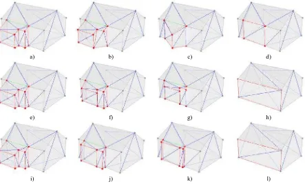
The most straightforward approach is to organize operations according to the length of the edges to be collapsed, where the preference is given to shorter ones. Such a simple strategy enables to achieve the smallest possible alteration of the model at each transformation step and thus ensures a gradual transition from one LOD to another. It has to be noted that edge collapse operations usually change the lengths of adjacent edges and that an edge sorting must be corrected accordingly after each transformation step. In order to give an idea of how this strategy works, Figure 3 a)-d) shows some intermediate states during the transformation of two LODs. It can be observed that the transformation starts in the middle part of the extrusion where the shortest elements are. So at first, the transformation takes place rather locally and only then gradually spreads to the global level where the larger parts of the model are eliminated.
It becomes apparent that without further geometric constraints, the process results in a high level of fragmentation of the effected faces. Edges that are far apart from one another and that do not belong to the same faces are collapsed together. And the resulting shape of the components therefore lose their planarity and rectangularity properties in intermediate steps. Figure 3 b) demonstrates how a set of planar rectangles can be distorted into a surface consisting of three rather wildly oriented triangles (bounded by red edges). But also planar faces can be created that have no counterpart in the original model. Both considerably alter the shape characteristics of the building model in intermediate steps, before the front part is finally merged with the joint plain (see Figure 2 c)).
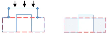
A severe problem, which is caused by uncontrolled edge collapse operations, is that intermediate representations of a building model might not be valid solids. Figure 1 illustrates an example where the collapse of the two shortest edges that are adjacent to the top line segment causes this line segment to be moved downwards to the top part of the (red) target LOD of rectangular shape. As this operation moves the top line segment over the lower line segment, a self-intersection within the model occurs, which leads to an incorrect geometry that also appears visually confusing to the viewers. This has to be avoided by all costs by choosing another edge for the next collapse operation instead of the shortest one.
Figure 1. Self-intersection of a building model caused by the Shortest Edge First transformation strategy (blue – initial LOD, red – target LOD).
3.2 Push Plane
Unlike the previous approach, the next two strategies primarily aim to take the shape of a building into account and establish a strict operation order for adjacent elements. The Push Plane approach assumes a main transformation direction, which determines the overall transformation process. This plane is defined as being parallel to the joint plane of the main building and the component to be removed. It serves to coordinate a gradual node shift towards the joint plane along its normal vector (see Figure 3 e)-h)). Here, the plane starts at the node that is furthest away from the main building component and is then pushed towards it. Every node that the plane hits is dragged along its normal direction. Edges are shortened during this process and removed if they degenerate to a single point. This strategy proves to be very effective for rectangular block structures that are parallel to the join plane (cf. Figure 3 a)-b)).
a) b) c) d)
Figure 3. Comparison of the three transformation strategies between different LODs: Shortest Edge First a)-d), Push Plane e)-h), and Sweep Plane i)-l) (red – nodes and edges which have to be eliminated, green – joint edges, blue – temporary TIN).
The Push Plane strategy starts out purely geometrical as the nodes are pushed along the plane during the transformation. Topological changes only happen if two nodes of an edge coincide or if the plane reaches the joint plane of the main component. Unnecessary edges and vertices of the pushed component can then be removed from the triangle mesh. Care has to be taken if the edges are still explicitly rendered as they need to be blended out before a sequence of operations removes the vertices and edges within the now coplanar joint face. Certain finalization sequences can be defined in order to ensure a uniform transformation concept (see Figure 4).
a)
b)
Figure 4. Two sequences of operations that finalize the triangle mesh after a Push Plane transformation.
Figure 4 a) shows a case where the projection of the eliminated element on the joint plane has no explicit connection with the grey edges of the surrounding polygon. The edge collapse restrictions in (Kada et al., 2015) would normally not allow to collapse any of the blue edges as they originate from a temporary triangulation. In such cases, the restriction is, however, loosened so that the remaining ring of red edges can be eliminated by three edge collapses that result in a single node. This node is then collapsed along the corresponding blue edge to the nearest node of the main solid. The constellation
depicted in Figure 4 b) is even easier to solve as the remaining middle component has two common (green) edges with the joint plane so that edge collapse can be generated along the grey edges till all unnecessary triangles of the original component are completely removed.
3.3 Sweep Plane
The main shortcoming of the two described strategies is primarily caused by the fact that neither of them actually takes into account the shape and complexity of the eliminated elements. The strategy Shortest Edge First primarily performs local alterations of the model while Push Plane defines only a general transformation direction which can contradict the orientation of individual edges and acts regardless of the size and shape of the joint part of the model. A high number of self-intersections is therefore a key problem of both approaches. Hence, the next strategy can be regarded as an attempt to combine the benefits of the previous ones by possibly avoiding their negative aspects.
The Sweep Plane strategy also uses a plane to coordinate the transformation. However, its primary purpose is not the geometric transformation itself, but works as a mean to synchronize the edge collapse operations within the triangle mesh. The so called sweep plane is initialized parallel to the joint plane and starts its parallel translation towards the main body from the most distant point. Most importantly, the actual transformation is completely based on the directions of existing edges to build a transformation path. Whenever the sweep plane hits a node, an impulse is generated that provokes an edge collapse in order to reach the joint plane as soon as possible. For this purpose, all the edges incident to the hit node are considered according to the following two parameters: the angle between the edge vector and the normal vector of the joint plane
a) b) c) d)
e) f) g) h)
∠(e, p) and the length of the edge d(e). The total value of the edge weight score(e) is then determined as:
score(e) = 0.75 · ∠(e,p) + 0.25 · d(e) (1)
The score favors one edge over another primarily by its smaller angles towards the joint plane and only secondly by its length. It ensures the fastest transformation in the direction of the main building component. The edge collapse will also be generated in sync for all edges whose nodes are hit by the sweep plane. Figure 3 i)-l) gives insight into how this strategy works, especial in comparison with the two previously described approaches. In this example, we can see that after the front portion of the extruded element is eliminated, the transformation continues to eliminate the remaining two red edges simultaneously with the rest of the element (cf. Figure 3 j) and k)) as all of them are hit by the sweep plane at this position.
Generally, this transformation approach looks very similar to the results generated by the Push Plane strategy, mainly due to the operation order. Nevertheless, the significant improvement lies in how edge collapse operations are triggered. In the Push Plane strategy, nodes are dragged along the plane and their incident edges are only collapsed if their two end points happen to coincide. Only in the end of the plane movement, the edges that lie within a face can be cleared by edge collapse operations. The Sweep Plane triggers edge collapse operations every time it hits a node incident to an edge. This reduces the number of operations and eases their execution without disturbing the shape of the building models. No post-processing is necessary.
3.4 Animation Timelines
To achieve a smooth animation that runs in accordance to the transformation strategies, the operations are stored in their given order. This enables to generate any intermediate state of a building model between its initial and resulting LOD. Nodes are therein moved along the collapsed edges or the push plane.
Each strategy defines its own animation timeline that is specific on whether edge collapse or node movement operations are initialized. During the Shortest Edge First strategy, edge collapse operations are executed one after another and its animation path is fully performed for a single edge at a time. Therefore, the duration of a full transformation from one LOD to the next LOD can be considered proportional to the length of a transformation list, i.e. to the amount of operations and the time each operation takes to be animated. However, in order to make a transformation appear smooth and dynamic, it is rather more suitable to associate the overall timeline with the total length of all collapsed edges. So that the time interval for each collapse operation is calculated in accordance with the length of a corresponding edge.
Unlike the previous approach, the Push Plane transformation is completely coordinated by the plane that gradually moves the nodes to the main building component. As soon as the plane reaches a node, it will be steadily shifted along towards the joint plane with all the other nodes that have been hit by this plane. Hence, the state of a model in a specific moment of time is in direct relation of the actual position of the push plane to the overall distance to the joint plane at the beginning of the transformation. In order to simulate this push plane movement, the distance to the joint plane will be calculated for each of the shifted nodes and consequentially its rate within the whole transformation interval which can be considered as the initiation point for a node shift.
Despite of some similarities, the chronology of a Sweep Plane transformation should be organized differently as the state of a model does not directly depend on the distance between the sweep and joint planes. Here, several collapse operations can run simultaneously and end before the joint plane is reached. Moreover, the end of one operation does not necessarily mean the beginning of the next one like in the first approach. For this reason, each collapse operation is specified by a begin and end parameter. Here, the time interval for each operation is proportional to the length of the corresponding edge.
a)
b)
c)
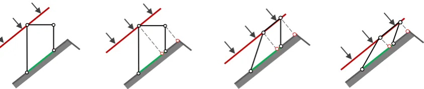
Figure 6. Projection of the eliminated building component onto the inclined joint plane in compliance with the Push Plane strategy (green – joint plane, red – transformation plane, black – eliminated component).
a) b) c) d)
Figure 7. Problem cases of the Push Plane strategy.
4. DISCUSSION AND RESULTS
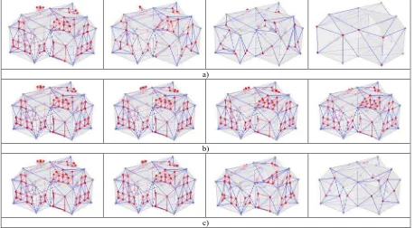
In order to fully and accurately understand how the proposed strategies function, they were not only applied to simple block buildings, but also to more complex models that additionally possess some semantic information like windows and smaller roof structures as shown in Figure 5. This example gives some intermediate steps of the transformation process so that the effect of each strategy can be visually compared with each other.
4.1 Impact of Transformation Strategies on Semantic Components of a Model
The Shortest Edge First strategy has generally a noticeable influence on the semantic elements of the model like windows and smaller roof constructions. Figure 5 a) clearly reveals that the shape of these predominantly rectangular structures endure the most drastic change during the intermediate steps of the transformation. Thus, e.g. window elements lose stepwise one edge after another so that they gradually degenerate into triangles and then into line segments that finally become single nodes.
4.2 Transformation of Elements with an Inclined Joint Plane
The final state of the Push Plane transformation represents nothing else than a projection of all nodes onto the joint plane between the component and the main body. This becomes particularly interesting in the case of an inclined joint plane. Figure 6 shows the transformation of a vertical roof structure, e.g. a chimney, that is projected onto the roof plane while all its nodes remain available. This is exactly the point at which the validity of the model is violated as self-intersections within the roof polygon emerge. This case even gets worse when the projected points of the component stand out of the actual model and literally remain “hanging” in the air (see Figure 7 a) and
b)). Although this problem becomes obvious during the final steps of the transformation, a reasonable solution could consist of detecting such constellations right from the beginning, so that they can be treated accordingly in a way that is different from the main strategy. For example, the element can be simultaneously reduced in several directions so that it shrinks in overall size in order to fit the joint element in the end and to avoid a pop-up effect.
A similar problem with a somewhat different geometrical background appears in the situation where a to be eliminated component has several joint planes on the main solid. Here, a possible solution can make use of several Push Planes at a time during the transformation as shown in Figure 7 c). However, the unambiguous assignment of each point of the element to a specific plane is a key problem which could be difficult to resolve. Another solution implies only one coordinating plane, which can be represented by some sort of an average over the initial joint planes (see Figure 7 d)). This example also illustrates that at some point of the transformation, the whole element can be split up in two parts which can negatively influence the perception of the process. The handling of this situation is also clearly worth of discussion in the scope of future work.
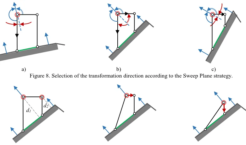
A closer look needs to be taken at the transformation of vertical elements with an inclined joint plane by a Sweep Plane strategy. According to equation (1), the edge that is most distant from the joint plane will be selected based on its orientation with respect
to the perpendicular of this plane, so that 0° ≤ ∠(e,p) < 180°.
a) b) c) Figure 8. Selection of the transformation direction according to the Sweep Plane strategy.
Figure 9. Sweep Plane transformation of an element with an inclined joint plane.
∠ (e,p) = min( angle(e,p), 180° - angle(e,p) ) (2)
The closer the orientation of such an angle is to the perpendicular of the joint plane, the more the corresponding edge is favored. Black arrows in Figure 8 a) and c) illustrate which transformation direction (vertical or horizontal) will be generally selected depending on the slope of the joint plane. In case of equivalence of the orientation angles (see Figure 8 b)) the weight of an edge will only depend on its length. An example of the transformation process for such an element of a building model, e.g. a chimney, is shown in Figure 9. Starting from the node that is furthest to the joint plane (the distance d1), the transformation eliminates consequently horizontal edges and then vertical edges, which leads to the major distortion of component’s shape. Therefore, another transformation procedure could be conceivable in this case in order to take into account the orientation of the eliminated component itself and thus better preserve its shape, e.g. to push it down parallel to its upper horizontal edge.
5. CONCLUSION
In this paper, three different animation strategies are suggested for smooth transformations between discrete LODs of a 3D building model. Based on various case examples, their properties are profoundly analyzed and compared to each other. Thus, despite the simplicity of the Shortest Edge First strategy, its visualization clearly shows that edge collapses, which take place at different parts of a model, give the impression of a rather random chaotic transformation. The lack of an ordered operation sequence appears to be quite irritating for a human viewer. Furthermore, the consequential violation of rectangularity and collinearity constraints of a model can make an object practically unrecognizable at some transition points what only complicates the perception of the whole transformation.
In spite of special cases mentioned above, the Push Plane strategy offers a robust overall solution for a smooth transformation process. Its visualization seems comprehensible
and easy to follow for a human viewer. Although, a finalization procedure is inevitably required in order to achieve the target state of the model. This particularly concerns the eliminated components of a model with an inclined joint plane that can also consists of several differently oriented segments. The solution to avoid geometrical and topological violations resulting from the transformation could become an important extension of this approach and enables to improve significantly its performance.
The last approach, Sweep Plane, was especially developed for correct geometrical and topological transformation of more complex fragments of 3D building models. It can be considered as an enhanced version of the previous method and allows to avoid most of its typical difficulties. The strategy provides good results and the transformation process is easy for perception. However, the transformation of elements with an inclined joint plane still remains unsolved. A different handling of these parts of a building model can be an interesting topic for future research.
ACKNOWLEDGEMENTS
This work was supported by the German Research Foundation (DFG) [grant number KA 4027/1-1].
REFERENCES
Cohen-Or, D., Levin, D., Remez, O., 1999. Progressive Compression of Arbitrary Triangular Meshes. In: Proceedings of the Conference on Visualization ’99: Celebrating Ten Years, VIS ’99. IEEE Computer Society Press, Los Alamitos, CA, USA, pp. 67–72.
Forberg, A., 2007. Generalization of 3D Building Data based on a Scale-Space Approach. In: ISPRS Journal of Photogrammetry & Remote Sensing, Vol. 62 (2), pp. 104–111.
Giegl, M., Wimmer, M., 2007. Unpopping: Solving the Image-Space Blend Problem for Smooth Discrete LOD Transitions. In: Computer Graphics Forum, Vol. 26 (1), pp. 46-49.
Glander, T., Döllner, J., 2009. Abstract Representations for Interactive Visualization of Virtual 3D City Models. In: Computers, Environment and Urban Systems, Vol. 33 (5), pp. 375-387.
Hoppe, H., 1997. View-Dependent Refinement of Progressive Meshes, In: Proceedings of the 24th Annual Conference on Computer Graphics and Interactive Techniques, SIGGRAPH ’97, ACM Press/Addison-Wesley Publishing Co., New York, NY, USA, pp. 189–198.
Hoppe, H., 1996. Progressive Meshes, In: Proceedings of the 23rd Annual Conference on Computer Graphics and Interactive Techniques, SIGGRAPH ’96, ACM Press, New York, NY, USA, pp. 99–108.
Hummel, J.E., Biederman, I., 1992. Dynamic Binding in a Neural Network for Shape Recognition. In: Psychological Review, Vol. 99 (3), pp. 480-517.
Kada, M., 2006. 3D Building Generalization Based on Half-Space Modeling. In: International Archives of the Photogrammetry, Remote Sensing and Spatial Information Sciences, Vol. XXXVI-2/W40, pp. 58–64.
Kada, M., 2002. Automatic Generalisation of 3D Building Models. In: International Archives of the Photogrammetry, Remote Sensing and Spatial Information Sciences, Vol. XXXIV, Part 4, pp. 243-248.
Kada, M., Wichmann, A., Hermes, T., 2015. Smooth Transformations between Generalized 3D Building Models for Visualization Purposes. In: Cartography and Geographic Information Science, Vol. 42(4), pp. 306-314.
Stadler, A., Kolbe, T.H., 2007. Spatio-Semantic Coherence in the Integration of 3D City Models. In International Archives of the Photogrammetry, Remote Sensing and Spatial Information Sciences, Vol. XXXVI-2/C43.
Lee, A.W.F., Dobkin, D., Sweldens, W., Schröder, P., 1999. Multiresolution Mesh Morphing. In: Proceedings of the 26th Annual Conference on Computer Graphics and Interactive Techniques, SIGGRAPH ’99, ACM Press/Addison-Wesley Publishing Co. New York, NY, USA, pp. 343-350.
Lindstrom, P., Koller, D., Ribarsky, W., Hodges, L.F., Faust, N., Turner, G.A., 1996. Real-Time, Continuous Level of Detail Rendering of Height Fields. In: Proceedings of the 23rd Annual Conference on Computer Graphics and Interactive Techniques, SIGGRAPH ’96, ACM Press, New York, NY, USA, pp. 109-118.
Luebke, D., Reddy, M., Cohen, J.D., Varshney, A., Watson, B., Huebner, R., 2003. Level of Detail for 3D Graphics. Morgan Kaufmann Publishers Inc., San Francisco, CA, USA.
Nesbitt, K.V., Friedrich, C., 2002. Applying Gestalt Principles to Animated Visualizations of Network Data. In: Proceedings of the Sixth International Conference on Information Visualisation, London, U.K., IEEE Computer Society, pp. 737-743.
Pajarola, R., 1998. Large Scale Terrain Visualization Using the Restricted Quadtree Triangulation. In: Proceedings of the Conference on Visualization ’98, VIS ’98. IEEE Computer Society Press, Los Alamitos, CA, USA, pp. 19-26.
Sander, P.V., Mitchell, J.L., 2006. Progressive Buffers: View-Dependent Geometry and Texture LOD Rendering. In: Proceedings of the Third Eurographics Symposium on Geometry Processing SGP ’05, Eurographics Association Aire-la-Ville, Switzerland, Switzerland.
Semmo, A., Trapp, M., Kyprianidis, J.E., Döllner, J., 2012. Interactive Visualization of Generalized Virtual 3D City Models using Level-of-Abstraction Transitions. In: Computer Graphics Forum, Vol. 31 (3pt1), pp. 885-894.
Sester, M., Brenner, C., 2005. Continuous Generalization for Visualization on Small Mobile Devices. In: Developments in Spatial Data Handling, Springer Berlin Heidelberg, pp. 355-368.
Thiemann, F., Sester, M., 2006. 3D-symbolization using adaptive templates. In: International Archives of the Photogrammetry, Remote Sensing and Spatial Information Sciences, Vol. XXXVI Part 2, pp. 109-114.
Ware, C., 2004. Information Visualization: Perception for De-sign. Morgan Kaufmann.