ACCURACY VERIFICATION OF GPS-INS METHOD IN INDONESIA
A.K.Mulyana a, A. Rizaldy b, K.Uesugi c, * a
The National Coordinating Agency For Surveys And Mapping, Cibinong [email protected]
bThe National Coordinating Agency For Surveys And Mapping, Cibinong [email protected]
c
Pasco Corporation, NSDI Project Office, Menera Jamsostek 4
thFloor Jl. Jend Gatot Subrato No 38,
[email protected]
Commission I, WG I/2
KEY WORDS: GPS/INS, IMU, Adjustment, Image, Triangulation, Comparison
ABSTRACT:
Pasco Corporation (Japan) has been implementing a project in Indonesia for Sumatra Island which is named Data Acquisition and Production on the National Geo-Spatial Data Infrastructure (NSDI) Development. Digital aerial images in 25cm GSD for 1:10,000 scale mapping have been taken as a part of the project. The owner of the project, The National Coordinating Agency for Surveys and Mapping (Bakosurtanal) planned to apply conventional aerial triangulation method as the initial stage. Pasco recommended Direct Geo-Reference Methodology by using GPS-IMU measurements and carried out a verification work in a city area. Measurements of tie points were implemented by using KLT/ATLAS software manually and adjusted by BINGO software. Aerial triangulation accuracy verifications were done by using one height control in the block center, one GCP in the center and four GCPs at the corners and one in the center. The results are sequentially, rms X,Y= 0.410cm, rms Z= 0.394cm (one height control point), rms X,Y= 0.430cm, rms Z= 0.392cm (one GCP) and rms X,Y= 0.356cm, rms Z= 0.395cm (5 GCPs). 5 GCPs for each block in official applications have been preferred for safety reasons. Comparisons of direct geo-referencing results with geodetic check points and aerial triangulation block adjustments have been done. The details of the work have been given in this study.
* Corresponding author.
International Archives of the Photogrammetry, Remote Sensing and Spatial Information Sciences, Volume XXXIX-B1, 2012 XXII ISPRS Congress, 25 August – 01 September 2012, Melbourne, Australia
1. INTRODUCTION
This work compiles the verification accuracy of position & attitude in the digital photography integrated with GPS/IMU for the project conducted in Sumatra Island of Indonesia. At first, it was planned to conduct the traditional aerial triangulation method in the project planning phase. However, this project was contracted by PASCO, a company in Japan with several experiences in the Digital Aerial Photography and GPS/IMU (Inertial Measurement Unit) for the past 10 years. Additionally, PASCO has joined as a member of the working group for creating new standard of the national aerial survey by Geospatial Information Authority of Japan (GSI). In this verification, PASCO clarified whether 1/10,000 mapping methodology could be applied by using GPS/IMU in Indonesia, and in order to perform aerial triangulation (AT), how much can reduce the number of GCPs (Ground Control Point).
PASCO carried out the aerial photography of the four cities, Medan, Pekanbaru, Padang and Jambi, for the NSDI project; however the verification about direct geo-referencing was done only in the Medan city with digital images in 25 cm GSD (Ground Sampling Distance).
2. SYSTEM AND METHODOLODY
AEROcontorol GPS/IMU system from the IGI mbH was utilized in this project. The features and performance are shown below, referred from the product catalogue.
I. Features
• Determine with high accuracy position and attitude (Exterior Orientation parameter) when camera is exposed.
• GPS reference station must be on the ground during flight mission.
• System is a combination of GPS and IMU.
II. Performance
• Accuracy of position: 0.05 m
• Accuracy of roll, pitch: 0.004 DEG
• Accuracy of Heading: 0.01 DEG
• GPS: 12 channel L1/L2 DGPS.
Figure 1. CCNS4 & AEROcontrol
It is necessary to determine the value of the IMU misalignment before taking aerial photography integrated with GPS/IMU. Boresight calibration has been carried out in the vicinity of
MEDAN airport. Below shows the conditions of the boresight calibration and flight plan.
Figure 2. Flight plan of the boresight calibration
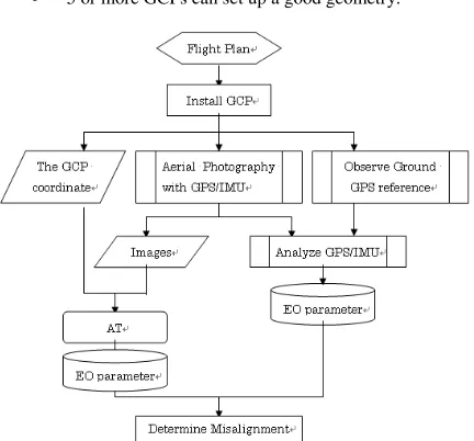
Boresight calibration is the work of calculation misalignment with aerial camera and IMU. This work is conducted to determine the value of its correction by comparing the exterior orientation parameters from aerial triangulation and direct geo-referencing. This involves usually the following conditions.
• About 10 shots per 1 strip in every 4 strips,
• Next strip can be taken to reverse of the flight direction,
• 5 or more GCPs can set up a good geometry.
Figure 3. Work Flow for the boresight calibration
GCPs were installed around the center and 4 corners of the block and surveyed by applying static method of the GPS.
Aerial photography integrated with GPS/IMU for boresight calibration was operated in the following manner;
• Utilization of the UltraCAM-X manufactured by Vexcel Imaging GmbH (a Microsoft Company) for the Digital Aerial Photography.
• Photography was carried out for the simultaneous observation of one epoch by one second in ground International Archives of the Photogrammetry, Remote Sensing and Spatial Information Sciences, Volume XXXIX-B1, 2012
XXII ISPRS Congress, 25 August – 01 September 2012, Melbourne, Australia
GPS reference station.
• Exposure condition is shown as below.
Focal
Table 1. Boresight calibration flight
Aerial Triangulation was carried out in the traditional way (we observed photo coordinates for tie points manually using KLT/ATLAS, and calculated by the BINGO bundle block
Table 2. Accuracy of GCPs & tie points
The attitude of each photo center at an exposure time was calculated by IMU analysis using AeroOffice software. GPS/INS position difference is within 0.10 m and INS/KF accelerometer bias is within -10000 g which are in acceptable level.
Comparing the exterior orientation parameter calculated by AT and obtained by GPS/IMU, the misalignment of IMU and camera was calculated. Those are correction values for analysis of GPS/IMU data and are used until the removal of camera and IMU devices. When they are removed from each other, boresight calibration is performed again.
3. APPLICATION
Aerial photography for 1:10,000 scale topographic mapping was planned with digital images in 25 cm GSD for Medan city area. It is very flat area and elevation ranges from 0 m to 100 m.
For kinematic GPS solution reference stations were used considering the GSI (Geo-Spatial Information Authority of Japan) standard, the ground GPS reference station should be installed where the position does not exceed 70km from the target area. The GPS/IMU observation was recorded at second interval during flight, and was needed for camera position (X0, Y0, Z0) by processing the kinematic GPS between ground GPS reference station and on board GPS.
Typically, IMU characteristic has the increasing cumulative error in constant velocity and straight flight. It was the longest length of one flight line around 40km in MEDAN, and it did not create any problem for this cumulative error.
Since data acquisitions were done within 25cm ground resolution in this project, flight altitude was planned 3,100m
above from the mean sea level. In case of GPS/IMU, it is not an impact of the position accuracy to determine the position and attitude of the camera directly.
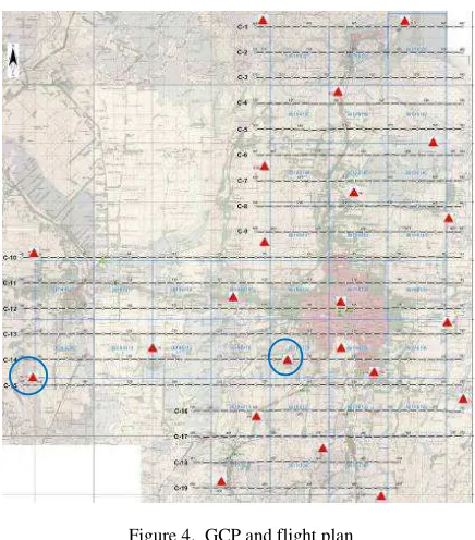
22 GCPs were established to implement verification measurements. Figure 4. shows the project area and GCP distribution (blue circles are GPS reference stations).
Figure 4. GCP and flight plan
UltraCam-X (by Vexcel Imaging GbmH) digital frame camera with focal length 100.500mm, image size in panchromatic mode 9,420*14,430 pixel was used in that application.
After calculation of exterior orientation parameter, the verification (check) points were measured by Stereo Plotter (Summit Evolution), and compared with GPS survey coordinates.
Figure 5. Workflow for GPS/IMU processing
4. RESULTS AND CONCLUSION
Following measurements and analysis have been implemented to verify the accuracy of Direct Geo-referencing by GPS/IMU.
• Stereo models were created by exterior orientation parameters which were results of direct geo-referencing. 22 GCPs measured in stereo models and International Archives of the Photogrammetry, Remote Sensing and Spatial Information Sciences, Volume XXXIX-B1, 2012
XXII ISPRS Congress, 25 August – 01 September 2012, Melbourne, Australia
compared (as check points-CPs) with the geodetic coordinates. The results are at Table 3.
GCP
• Aerial triangulation measurements and block adjustments with three different control point configurations (one height control in the block centre, one full control in the centre, 4 GCPs at the corners and 1 in the centre) have been implemented. The results are at Table 4.
The number of the GCP does not affect the vertical accuracy of the block. Better horizontal accuracy can be provided by using 4 or 5 GCPs in the block, even though one height control point is enough to get accuracy for 1:10,000 scale mapping. But, PASCO has been recommending using 5 GCPs for safety reasons.
On the other hand, it can be concluded that direct geo-referencing is highly reliable in that scale when the tables 3 and 4 compared. Aerial triangulation provides better vertical accuracy than direct geo-referencing, but horizontal accuracies for both comparisons are almost in the same level.
GCP
Table 4. Comparison of Direct Geo-referencing with AT
Accuracy expectations for Bakosurtanal (Indonesia) in 1:10,000 scale topographic mapping are; HO= ± 2 m, VE= ± 1.5 m. Mapping in forest areas like Kalimantan and Sumatra may be harder than any other area. Establishment and surveying of GCPs might be difficult, so, direct geo-referencing can be applied in such areas without any hesitation. Even though vertical accuracy is in the range of value at specification, aerial triangulation measurement and integrated geo-referencing (AT with GPS/IMU data) with only one ground control point (vertical control point) can be applied to increase the vertical accuracy.
International Archives of the Photogrammetry, Remote Sensing and Spatial Information Sciences, Volume XXXIX-B1, 2012 XXII ISPRS Congress, 25 August – 01 September 2012, Melbourne, Australia