APPLICATION OF VISION METROLOGY TO IN-ORBIT MEASUREMENT OF LARGE
REFLECTOR ONBOARD COMMUNICATION SATELLITE FOR NEXT GENERATION
MOBILE SATELLITE COMMUNICATION
M. Akioka a, T. Orikasa a, M. Satoha A. Miura a, H. Tsuji a, M.Toyoshima a, Y.Fujino a
a National Institute of Information and Communications Technology, Nukuikita, Koganei, 184-9795 Tokyo, Japan - (akioka, t.orikasa,
satoh310, amane, tsuji, morio, fujino)@nict.go.jp
Commission V, WG V/1
KEY WORDS: Vision Metrology in Orbit, Communication Satellite, Large Deployable Antenna
ABSTRACT:
Satellite for next generation mobile satellite communication service with small personal terminal requires onboard antenna with very large aperture reflector larger than twenty meters diameter because small personal terminal with lower power consumption in ground base requires the large onboard reflector with high antenna gain. But, large deployable antenna will deform in orbit because the antenna is not a solid dish but the flexible structure with fine cable and mesh supported by truss.
Deformation of reflector shape deteriorate the antenna performance and quality and stability of communication service. However, in case of digital beam forming antenna with phased array can modify the antenna beam performance due to adjustment of excitation amplitude and excitation phase. If we can measure the reflector shape precisely in orbit, beam pattern and antenna performance can be compensated with the updated excitation amplitude and excitation phase parameters optimized for the reflector shape measured every moment.
Softbank Corporation and National Institute of Information and Communications Technology has started the project "R&D on dynamic beam control technique for next generation mobile communication satellite" as a contracted research project sponsored by Ministry of Internal Affairs and Communication of Japan.
In this topic, one of the problem in vision metrology application is a strong constraints on geometry for camera arrangement on satellite bus with very limited space. On satellite in orbit, we cannot take many images from many different directions as ordinary vision metrology measurement and the available area for camera positioning is quite limited. Feasibility of vision metrology application and general methodology to apply to future mobile satellite communication satellite is to be found. Our approach is as follows:
1) Development of prototyping simulator to evaluate the expected precision for network design in zero order and first order
2) Trial measurement for large structure with similar dimension with large deployable reflector to confirm the validity of the network design and instrumentation.
In this report, the overview of this R&D project and the results of feasibility study of network design based on simulations on vision metrology and beam pattern compensation of antenna with very large reflector in orbit is discussed. The feasibility of assumed network design for vision metrology and satisfaction of accuracy requirements are discussed. The feasibility of beam pattern compensation by using accurately measured reflector shape is confirmed with antenna pattern simulation for deformed parabola reflector. If reflector surface of communication satellite can be measured routinely in orbit, the antenna pattern can be compensated and maintain the high performance every moment.
1. INTRODUCTION
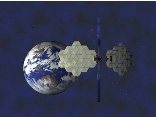
For mobile satellite communication service, miniaturization user terminal including mobile satellite phone is an important issue. For miniaturization of ground base terminal, high performance of satellite as well as reducing antenna size and output power of ground terminal is required. A very large aperture reflector antenna onboard satellite is the promising option for future mobile communication satellite to reduce the size of user terminal antenna size and output power. Figure 1 is the artist's drawing of the Engineering Testing Satellite VIII (ETS-VIII) developed by National Institute of Information and Communications Technology (NICT) and Japan Aerospace eXploration Agency (JAXA) (Suzuki 2003). The satellite is for development and experiment for mobile satellite communication technology equipped with two large deployable reflectors with thirteen meters diameter for transmission and reception of
communication signal for mobile satellite communications technology experiment in orbit.
Figure 2 is the orbital photographic image of large deployable reflector of thirteen meters aperture for reception on board ETS-VIII. The deployable reflector is flexible structure consisting of metallic mesh and surface cable for tension instead of hard dish reflector as ordinal satellite parabola antenna. The flexible reflector is deployed in orbit after launch. For enough electric performance of antenna, high accuracy of parabola reflector shape is required to avoid the change of quality due to aberration. Thermal deformation due to temperature variation in geosynchronous earth orbit is considered as important concern coming from the orbital experiment with Engineering Testing Satellite VIII (Kiku - 8) launched on December 2006. In the antenna pattern measurement experiment of ETS-VIII, pointing offset and change of antenna pattern is observed. The observed offset of beam center is about 100 km or 0.15 degree in some case (Satoh et. al 2011). The change is considered due to the
The International Archives of the Photogrammetry, Remote Sensing and Spatial Information Sciences, Volume XLI-B5, 2016 XXIII ISPRS Congress, 12–19 July 2016, Prague, Czech Republic
This contribution has been peer-reviewed.
thermal deformation of reflector caused by the change of thermal environment and temperature of antenna structure in flexible structure.
Figure 1. Artist's drawing of the Engineering Testing Satellite VIII (ETS-VIII) developed by National Institute of Information and Communications Technology (NICT) and Japan Aerospace eXploration Agency (JAXA). (Courtesy of JAXA)
Figure 2. In orbit photographic image of large deployable Reflector for reception onboard Engineering Testing Satellite VIII (Courtesy of JAXA)
Deformation of reflector shape deteriorate the antenna beam performance and quality of communication service. For accommodation of huge number of user and wide coverage for service, multi-beam system with frequency re-use with digital beam former (DBF) and digital chanellizer (DC) will be a plausible option for next generation mobile communication satellite. In case of digital beam forming antenna with phased array can modify the antenna beam performance and quality due to adjustment of excitation amplitude and excitation phase. If we
can measure the reflector shape precisely in orbit, beam pattern and antenna performance can be compensated continuously with the updated excitation amplitude and excitation phase parameters optimized for the reflector shape measured every moment. Softbank Corporation and National Institute of Information and Communications Technology has started the project "R&D on dynamic beam control technique for next generation mobile communication satellite" as a contracted research project sponsored by Ministry of Internal Affairs and Communication of Japan (Ministry of Internal Affairs and Communications 2014). The project consists of following three research topics.
(i) Development of foot-print measurement system in network (ii)Application of vision metrology for measurement of large reflector shape
(iii)Excitation amplitude and excitation phase control to compensate antenna pattern change.
In this topic, point on vision metrology application is the very limited geometry for camera arrangement on satellite bus. On satellite in orbit, it is difficult to take many images from many different directions as ordinary vision metrology measurement and the available area for camera positioning is quite limited. Typical size of satellite bus is several meters, which may be not enough for baseline of vision metrology for large reflector larger than twenty meters locating fifteen or twenty meters from satellite bus. Feasibility of vision metrology application and general methodology to apply to future mobile satellite communication satellite is to be found by detail network design, simulation, and experiments.
2. FEASIBILITY OF NETWORK DESIGN AND EXPECTED PRECISION EVALUATION BY
SIMULATION
Vision metrology for large onboard reflector in orbit is a challenge without precedents. The preliminary requirement target for reflector measurement accuracy is around five millimeters in orbit. To obtain appropriate photogrammetric network design for large reflector of communication satellite, we executed a simulation for assumed reflector and satellite bus geometry (Akioka et. al 2016). Followings are the overview of the simulation results.
Assumed parameter for satellite reflector is as follows: Diameter of reflector 22 meters
Focal length 13.2 meters Focal Ratio (F/D) 0.6
Based on the assumed focal length, distance between reflector apex and cameras near antenna feed or on satellite bus is about thirteen or fifteen meters. At the initial step, photogrammetric network consisting of four camera is assumed for measurement. If the obtained precision from simulation is not enough for the requirement, the network design including the number of cameras would be updated.
The parameters of camera are based on commercially available CCD tips for high grade measurement (Table I). The f in this table is the assumed focal length of lenses which is suitable for the twenty meters reflector. Outline of the simulation to confirm the convergence of bundle adjustment and expected precision in trial and error basis is as follows: (Akimoto 2002)
(1)Setting the measurement target
Three dimensional coordinates of assumed measurement targets are set. About two hundreds measurement point are assumed in our simulation.
(2)Setting the specification of four cameras.
The International Archives of the Photogrammetry, Remote Sensing and Spatial Information Sciences, Volume XLI-B5, 2016 XXIII ISPRS Congress, 12–19 July 2016, Prague, Czech Republic
This contribution has been peer-reviewed.
The pixel number and dimension of imager device, focal length of lens are provided for assumed cameras.
(3)Setting nominal external orientation (position and orientation of camera)
Appropriate nominal external orientation for each cameras are provided in accordance with the assumed geometrical configuration.
(4)Setting the target recognition error
In this simulation, 0.1 pixels is assumed based on our previous experiences.
(5)Photograph image calculation for targets assumed in step (1) (6)Execution of bundle adjustment calculation
(7)Dispersion of coordinates derived by bundle adjustment changing exterior orientation parameters.
Table I: List of samples camera format assumed in
simulation based on CCD tips list for commercially
available high performance camera system including for
astronomical use.
Table II: Results of simulation of photogrammetric
network feasibility for 4m by 2m camera arrangement
number
Assumed exterior orientation parameters, positions and orientations of four cameras, and target recognition errors are changed as perturbations in random number basis and the coordinates of measurement targets are derived by bundle adjustment calculation. The dispersion of calculated coordinates are evaluated as expected measurement precision. If the calculation is not convergent, the assumed network design should be abandoned.
The table II is simulation results for various cameras specifications and formats listed in table I.The separation of each camera is set four meters by four meters. On table II, sx, sy, sz is the RMS of standard deviations of calculated coordinates of measurement target for fifty trials with perturbations of external orientation and target recognition errors on random number basis. The expected precision for 4M pixel camera (case (2) on table I) is better than five millimeters which is the preliminary requirement.
3. FEASIBILITY OF BEAM COMPENSATION BY OPTIMIZATION BY MEASURED REFLECTOR SHAPE
IN ORBIT
In this section, the feasibility of beam pattern compensation by using accurately measured reflector shape is discussed. The parabola reflector with thirteen meters aperture and 37 elements feed is assumed for the beam pattern simulation for antenna. The assumed reflector geometry is partly compatible with the reflector onboard ETS-VIII satellite. The linearly inclined distortion superimposed onto the ideal parabola shape is assumed as deformed reflector for beam pattern compensation simulation. The beam pattern deteriorated with the parabola surface deformation is examined and the compensated beam pattern by optimizing excitation amplitude and phase parameter for phased array feed is shown.
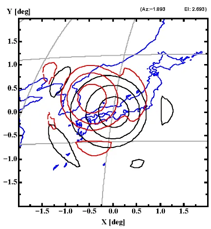
Figure 3: Comparison of the beam pattern for ideal parabola reflector without no deformation and nominal excitation amplitude and phase parameter (black contour) and the beam pattern for deformed reflector and same excitation amplitude and phase parameter with the nominal parameter. The contour level is -3dB, -10dB, -20dB of peak antenna gain near beam center. Horizontal axis and vertical axis is the azimuth and elevation angle from the satellite at Geo-synchronous orbit 36,000 kilo meters above the ground.
In Figure 3, the black contour is the beam pattern for ideal parabola reflector without no deformation and nominal excitation amplitude and phase parameter. The nominal excitation amplitude and phase parameter is optimized for ideal parabola reflector with maximum ratio combining algorithm. The red contour is the beam pattern for deformed reflector and same excitation amplitude and phase parameter with the nominal parameter. If accurate reflector surface can be measured, beam pattern can be compensated dynamically by continuous optimization of the excitation amplitude and phase parameter
The International Archives of the Photogrammetry, Remote Sensing and Spatial Information Sciences, Volume XLI-B5, 2016 XXIII ISPRS Congress, 12–19 July 2016, Prague, Czech Republic
This contribution has been peer-reviewed.
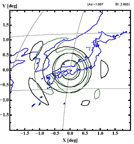
every moment. In Figure 4, beam pattern for deformed reflector with excitation parameter optimized for the deformed reflector surface shape. Black contour in Figure 4 is the same as in Figure 3 for comparison. Algorithm for optimization is the maximum ratio combining with constraints of peak antenna gain at the beam center. This simulation shows that the deteriorated beam pattern can be compensated by using excitation amplitude and phase parameter optimized to measure reflector surface. Therefore, if reflector surface of communication satellite can be measured routinely in orbit, the antenna pattern can be compensated and maintain the high performance every moment.
Figure 4: Comparison of the beam pattern for deformed reflector with excitation parameter optimized for the deformed reflector surface shape (green contour) and the beam pattern for ideal parabola reflector without no deformation and nominal excitation amplitude and phase parameter (black contour). The contour level is -3dB, -10dB, -20dB of peak antenna gain near beam center. Horizontal axis and vertical axis is the azimuth and elevation angle from the satellite at Geo-synchronous orbit 36,000 kilo meters above the ground.
4. CONCLUDING REMARKS
In this paper, the overview of this R&D project and the results of feasibility study of network design based on simulations on vision metrology and beam pattern compensation of antenna with very large reflector in orbit is discussed. The feasibility of assumed network design for vision metrology and satisfaction of accuracy requirements are discussed. The feasibility of beam pattern compensation by using accurately measured reflector shape is confirmed with antenna pattern simulation for deformed parabola reflector. If reflector surface of communication satellite can be measured routinely in orbit, the antenna pattern can be compensated and maintain the high performance every moment.
ACKNOWLEDGEMENTS
This research and development is supported by Research and Development for Expansion of Radio Wave Resources in Radio Spectrum User Fee System operated by Ministry of Internal Affairs and Communications of Japan.
The authors are grateful to Mr. Naokazu Hamamoto, former research manager of Wireless Network Research Laboratory, National Institute of Information and Communications Technology, for helpful discussion and advice as well as very kind tutorial for the tools for antenna pattern evaluation developed during his careers in NICT.
One of the authors would like to thank Drs. Yukihito Kitazawa and Minoru Tagami for their kind help for executing the project efficiently.
REFERENCES
Akioka, M., Orikasa, T., Tsuji, H., Toyoshima, Y., Satoh, M., Fujino, Y., 2016, Dynamic Beam Control Based on Vision Metrology of Large Deployable Antenna for Mobile Satellite Communication, Acta Astronautica, in printing
Akimoto, K. 2002. Research of vision metrology for intelligent construction, Thesis of Kyoto University
Ministry of Internal Affairs and Communications, 2014, Basic research plan of Research and Development for Expansion of Radio Wave Resources, "R&D on dynamic beam control technique for next generation mobile communication satellite",
http://www.soumu.go.jp/menu_news/s-news/01kiban09_02000126.html , written in Japanese
Satoh, M., Orikasa, T., Fujino, Y., 2011. Evaluation of electrical Performance for Large-Scale Deployable Reflector Antenna Equipped with Engineering Test Satellite VIII on Orbit, IEICE TRANSACTIONS on Communications, Vol.J-94B, No.3,pp.344-352
Suzuki Y. (editor), 2003, Special Issue on the Engineering Test Satellite Ⅷ (ETS- Ⅷ), Journal of National Institute of Information and Communications Technology
The International Archives of the Photogrammetry, Remote Sensing and Spatial Information Sciences, Volume XLI-B5, 2016 XXIII ISPRS Congress, 12–19 July 2016, Prague, Czech Republic
This contribution has been peer-reviewed.