The Geometric Calibration and Validation for The ZY3-02 Satellite Optical Image
Xinming Tang a, Xiaoyong Zhu b, a,* a
Satellite Surveying and Mapping Application Center (SASMAC), National Administration of Surveying, Mapping and Geoinformation - (txm, zhuxy)@sasmac.cn
b
State Key Laboratory of Information Engineering in Surveying, Mapping and Remote Sensing (LIESMARS), Wuhan University. - [email protected]
KEY WORDS: the satellite ZY3-02; imaging geometric model; geometric calibration; interior orientation
ABSTRACT:
Chinese ZY3-02 satellite, which is the second of ZY3 series satellites, was launched in May 30th 2016 for complementing the mapping and earth observation. In order to eliminate various system errors of the platform and payload, the on-orbit geometric validation and calibration was carried out. Firstly, we introduced the parameters of the three-line stereo camera and multispectral camera bound on ZY3-02 in this paper. There are four optical cameras on ZY3-02: a 4-band nadir-looking multi-spectral camera with 5.8 m resolution, a 2.1m resolution nadir-looking panchromatic band camera, as well as 2.5m resolution forward- and backward-looking panchromatic band cameras. Compared with ZY3-01, the resolution of the forward- and backward-looking cameras on ZY3-02 were upgraded from 3.5 m to 2.5 m. Then we presented the methods and datasets used for calibration in details. After our calibration, the total positioning accuracy of the three-line camera images is better than 10m without ground control points (GCPs). The plane and height accuracy are improved to 3 and 2 m respectively, with few control points. The band-to-band registration accuracy of the multispectral camera is better than 0.15 pixels.
1. 1. INTRODUCTION
ZY3-01 satellite is the first Chinese civilian high-resolution stereo elevation mapping satellite, which was launched at the China Taiyuan Satellite Launch Center on January 9, 2012. ZY3-02 satellite, which is the second of ZY3 series satellites, was launched in May 30th 2016.These satellites are designed to process 1:50000-scale surveying and mapping products and to renew maps with a scale of 1:25000 or more, which are used primarily for surveying and monitoring territorial resources. The ZY-3 satellite products have achieved spatial resolution and geometric accuracy in line with the that of the international leaders.
There are also four optical cameras on ZY3-02: a 4-band nadir-looking multi-spectral camera with 5.8 m resolution, a 2.1m resolution nadir-looking panchromatic band camera, as well as 2.5m resolution forward- and backward-looking panchromatic band cameras. Compared with ZY3-01, the resolution of the forward- and backward-looking cameras on ZY3-02 were upgraded from 3.5 m to 2.5 m (Table 1).
The multi-spectral camera and three-line array cameras are all designed as multiple linear CCD sensors with parallel imaging, to increase the width of the remote sensing imagery. on ZY3-02; the nadir-, forward- and backward-looking panchromatic band cameras are equipped with three CCD line stitching with 23 overlapping pixels; the nadir multi-spectral imager is equipped with three multi-spectral CCD line stitching with 180 overlapping pixels.
Table 1. the comparison table about the payload parameters of ZY3-01 and ZY3-02
Details of the sensor payload on ZY3-01
Details of the sensor payload on ZY3-02 Payload Panchromatic band camera
(nadir, forward, and
Panchromatic band
band3(Red): 0.63–0.69 µm band4(Near-infrared): Forward and backward:
3.5 m multi-spectral 5.8 m
Nadir: 2.1 m Forward and backward: 2.5 m multi-spectral 5.8 m Pixel
numbers
Nadir:24576(8192×3)×7u m
Forward and backward: 16384(4096×4)×10um
nadir, forward, and backward 24576(8192×3)×7u
m The dual-frequency GPS receiver onboard ZY3-02 computes the position and speed of the satellite in real time using pseudorange measurements. Information regarding the original carrier phase measurement is recorded and transmitted to ground station for precise post-processing. The satellite attitude angle is computed in real time by a star sensor and gyroscope, and the data are recorded and transmitted to the ground station for precise satellite attitude post-processing. Thus, the system for satellite attitude control ensures the stability of the platform within 5 × 10⁻⁴ °/s. Table 2 lists the basic information pertaining to the GPS receiver, star sensor, and gyroscope onboard ZY-3.
Data type Information
GPS receiver
Data sampling
frequency 1 Hz
The accuracy of L1 pseudo-range measurement
≤ 50 cm (1 σ)
The accuracy of L2 pseudo-range measurement
≤ 50 cm (1 σ)
The accuracy of L1 carrier phase measurements
≤ 8 mm (1 σ)
The accuracy of L2 carrier phase
The accuracy of inertial attitude measurement
The geometric accuracy of satellite imagery is related closely to the satellite platform, payload, and ground-based data-processing system. Its accuracy could be affected by several factors, including the connecting position between the photographing center and image plane, the position and angle of the projection center and image plane to the ground. Therefore, the analysis and summary of the geometric processing of ZY3-02 data is of crucial significance to satellite design and application. This paper is not only gives a detailed look into the characteristics and product quality of ZY3-02 satellite data but also discussing the rigorous imaging geometric model, data processing, the methodology and flow of on-orbit geometric calibration. Furthermore, standard remote sensing imagery products without image distortions are processed after completion of the sensor calibration, and the geometric accuracy is analyzed.
2. METHODS 2.1 Rigorous imaging geometric model
The rigorous imaging geometric model describes the mathematical relation between object point coordinates in the image coordinate system ( , )x y and the geodetic coordinate system ( , , )X Y Z , which is the basis for the geometric processing. The established ZY3-02 rigorous imaging geometric model using the geometry characteristics of satellite imaging, as below:
S J body camera
S coordinate vector in the WGS84 coordinate system at the
moment of image acquisition, and
[
]
WGS84T
X Y Z is the object geometric coordinate of the image point in the WGS84 coordinate system. body
camera
R is the installed matrix of the camera, 84
2000 WGS J
R is the transformation matrix from the ECI coordinate frame to the ECEF coordinate frame ECI
ECEF
R , which is based on the IAU 2000 precession–nutation model of the IERS (International Earth Rotation and Reference Systems Service) convention, and J2000
body
R is the transformation matrix from the body coordinate frame to the ECI coordinate frame body
ECI R , which is measured by attitude equipment (such as star sensors and gyroscopes). Dx Dy DzT is the origin of the GPS phase center offsets in the body coordinate system,
T
x y z
d d d
is the camera coordinate system relative to the body coordinate system shift, (x y0, 0)is the principal point of the camera, f is the focal length of the camera, and (∆ ∆x, y)is the pixel distortion of the camera.
2.2 Geometric Calibration
2.2.1 Internal calibration model: For ZY3-02, internal calibration mainly concerns the parameters of the camera, including optical lens distortion, CCD distortion, and error focal length, and the principal point coordinates. According to ground-based test results, the three-line array camera is a compact optical system without distortion when the calibration model has accounted for several errors (e.g., focal length errors, principal point error, CCD stitching errors). The multispectral camera is a three-mirror off-axis optical system for which the edge-field distortion is approximately 50 µm or 2.5 pixels. Multi-spectral camera calibration modelling should not only take three-line focal-plane-array camera errors into account but also take optical system distortion in to view. For multi-line CCD sensors, the translation error of CCD
i
relative to the principal point (x y0, 0) is expressed as (∆x0 _i,∆y0 _i). The error symmetric distortion of the optical system is expressed as((k r1 2+k r x2 4) (k r1 2+k r2 4) )y . The decentering distortionof the optical system is expressed
as 2 2 2 2
1 2 1 2
(2p x y+p r( +2y ) 2p x y+p r( +2y )) , and the integrated error of each pixel on the CCD can be expressed by:
2
Different cameras exhibit different spectral distortion characteristics for each CCD linear array and each band, which requires a complex expression for each camera. It is more convenient to use two-dimensional field angles (ψ ψx y) for subsequent processing applications:
0
the pixel offsets caused by the distortion of the camera, and (ψ ψx y) represents the corresponding view angle.
2.2.2 External calibration model: For ZY3-02, the external calibration is intended to obtain an accurate relative position of the projection center in photography within the satellite position measurement coordinate system, i.e., an accurate angle of the main axis of photography within the attitude measurement system. In space-borne optical pushbroom imaging, there are different geometrical characteristics, whereby the positional and angle errors affect the accuracy of the position, however it can be equivalently processed based on certain geometric relationships. The offsets of the GPS satellite phase center and camera projection center in the satellite position measuring coordinate system can be the equivalent to angle. Therefore, the external calibration introduces the orthogonal rotation matrix
(bias matrix,
R
U) to compensate several errors: the offset anglefrom the main axis of photography to the star sensor measurement coordinate system, offset of the phase center, and offset of the projection center, as the formula 4. Because the star sensor measurement dates include long-period, short-period, and random errors, some errors and uncertainties in the coordinate system are established by the star sensor measurements. Using additional on-orbit calibration fields, the different bias matrices must be calibrated corresponding to each scene, whereas the external calibration results are obtained by weighting processing:
where superscript
i
represents the corresponding parameter ofscene
i
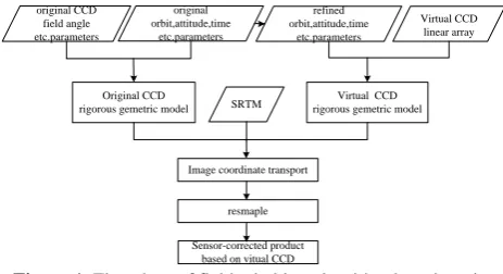
.2.3 Sensor-corrected products without image distortion On ZY3-02, multi TDI(Time Delay and Integration) CCD units are mounted on the focal plane of the cameras to achieve a wider effective swath. However, owing to the impacts of ground-based supply and testing, launch, and in-orbit operation, the real distribution of the TDI CCD units are not strictly linear. A simple shift or affine transformation of the TDI CCD images could guarantee virtually seamless stitched images; however, the stitched images do not have linear perspective, which means that there exists geometry seam.
The reimaging method based on a virtual CCD is used to re-image to eliminate the lens and CCD distortions for ZY3-02. The virtual CCD can be considered to form an image similar to that obtained by an ideal pinhole camera without lens distortion, and a single CCD unit is uniformly spaced in the focal plane. A regular integral time is used for the re-imaging.
processing. The steps of the re-imaging algorithm, based on a virtual CCD, are as follows:
1) Calculate object coordinates using the virtual CCD image point
According to the rigorous geometry imaging model of the virtual CCD, combined with the virtual field angle, and attitude and orbit parameters, each pixel of the virtual CCD is projected onto the average surface elevation or SRTM-DEM imaging area, from which we obtain the geodetic coordinates corresponding to the object point.
2) Calculate image point on the true image
According to the rigorous geometry imaging model of the real CCD, combined with the real field angle, and attitude and orbit parameters, such as the object-side point back projection to the real CCD, we obtain the corresponding point on the real image.
3) Grayscale resampling and assignment
The grayscale values of the virtual CCD points are assigned from real points after resampling.
By repeating the above steps to complete the re-imaging of the entire area, we obtain sensor-corrected product images. Figure 8 presents a flowchart of the field-stitching algorithm based on the virtual CCD.
original CCD based on vitual CCD
Figure 1. Flowchart of field-stitching algorithm based on the virtual CCD
3. DATA TEST
We haved processed ZY3-02 data by using the above method and have carried on the experimental verification.
3.1 On-Orbit Geometric Calibration
For the satellite ZY3-02, we have obtain the high precision intensive control points by registration satellite images and high resolution DOM/DEM registration based on phase correlation algorithm (LEPRINCE S 2007).And then, the parameter calibration model had been solved, on-orbit geometric calibration was been finished.
The calibration satellite images are acquired in July 28, 2016. The calibration reference data is Heilongjiang Zhaodong region where have 1:2000 DOM and DEM,which area is plain, height difference is less than 20m.
Table 3 the result of on-orbit geometric calibration for Satellite ZY3-02 (unit: pixel) before calibration External calibration Internal and External calibration
x y xy x y xy x y xy
NAD 29.124 4.402 29.455 0.435 0.146 0.458 0.196 0.131 0.236 FWD 21.831 13.460 25.647 0.835 0.885 1.217 0.216 0.167 0.273 BWD 11.924 17.518 21.191 1.128 0.254 1.156 0.118 0.157 0.196 MUXB2 4.855 2.216 5.337 0.276 0.293 0.402 0.155 0.131 0.203 Table 3 have shown that: for four cameras laid on ZY3-02, on
orbit geometric calibration can effectively eliminate the system error, the image internal accuracy is stability.
The RMS residuals both along the CCD direction and across the CCD direction are less than 0.3 pixels, and that fully meet the following application processing needs.
3.2 Geometric Validation
To verify the positioning accuracy of the ZY3-02 geometric model, 4 test areas were selected for accuracy evaluation of stereo image adjustment during the year after launch. Affine transformation parameters in image space were added to the adjustment model with the calibrated products. For free network adjustment, all points were selected as check points in the accuracy evaluation, whereas for the adjustment with control points, only some of the points were selected as control points and the others were used as check points. The ground control data were acquired by GPS field measurement. 3D measurement accuracy is better than 50 cm, and image coordinates acquired by artificial measurement have accuracy that can reach 0.5 pixels in flat areas and around 1 pixel in mountainous areas, as
topographic features in these areas are problematic for artificial recognition.
After an overall statistical review of the four test areas which the results show in table 4, the following conclusions were drawn:
Experimental
region Area Imaging time
Terrain
3 Heilongjiang
Qitaihe Table 3. The overview of The ZY3-02 datasets for Geometric Validation
X (RMS
)
Y (RMS
)
XY (RMS
)
X (RMS
)
Y (RMS
)
XY (RMS
)
H (RMS
)
1 3.965 12.2 12.82
8 1.532 2.006 2.524 2.606
2 3.228 7.35 8.028 0.406 0.689 0.8 1.463
3 5.726 10.68 8
12.12
6 1.813 2.15 2.812 2.148
4 3.258 4.239 5.346 0.814 1.447 1.660 2.639 Table 4. The Geometric Validation for The ZY3-02 in 4 test regions
Thus, the test results indicate that the geometric accuracy of ZY-3 images is stable, and that the affine transformation model in image space, established using several control points, can effectively reduce systematic errors
3.3 Band-to-Band Registration Verification
The satellite images for Band-to-Band registration verification are acquired in June 4, 2016 in Henan Dengfeng.B1, B3, B4 matching respectively with B2 matching, the 7285, 9384 and 7281 control points obtained are used for calibration and validation. The results are shown in table 5:
Table 5. Calibration accuracy of other bands of Henan Dengfeng
Spectrum project x y xy
B2-B1 Before calibration 1.261 0.675 2.045 After calibration 0.174 0.154 0.054 B2-B3 Before calibration 0.836 0.687 1.172 After calibration 0.161 0.150 0.048 B2-B4 Before calibration 1.559 0.754 2.998 After calibration 0.285 0.252 0.145 From table 5, B1, B3, B4 of the geometric calibration accuracy is better than 0.15 pixels, we can be understood as the Band-to-Band registration accuracy is less than 0.15 pixel. Because the distances between B3, B1, B4 and B2 on the focal plane are gradually increased and the accuracy of registration by the satellite position and attitude are gradually increased at the same time, the calibration accuracy also been affected.
Based on the inner orientation elements of each element of each spectrum obtained by the calibration, the virtual CCD reimaging algorithm is used to realize the band-to-band registration of the multi spectral segments.
Figure 2 is a test image local magnification of 6 times. Figure 2 (b) relative to figure 8 (a) shows that: after the band-to-band registration, of the land cover edge boundary is relatively clear, the "pseudo rainbow" phenomenon is eliminated. There are only the influence by imaging time inconsistency and the modulation transfer function are not the same.
In order to verify the accuracy of the band-to-band registration, the high precision registration algorithm is used for the dense matching between the spectral bands. The other spectral bands are registered with the first band, and the registration error are analyzed.
(a) Before Multispectral spectral registration
(a) After Multispectral spectral registration Fig2.The True color Comparison chart before and after
registration
(b) registration error across CCD direction before registration
(c) registration error along CCD direction after registration
(d) registration error across CCD direction after registration
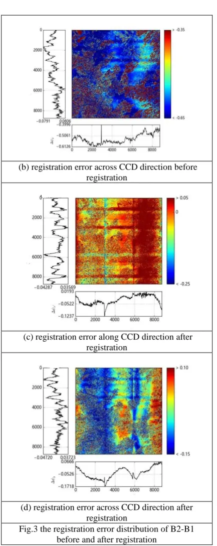
Fig.3 the registration error distribution of B2-B1 before and after registration
Figure 3 (a), figure 3 (b) are the results of before registration, figure 3 (c), figure 3 (d) are the results of after registration. Figure 3 (a), figure 3 (c) indicates the error of along CCD direction, figure 3 (b), figure 3 (d) indicates the error of across CCD direction. In Figure 3, colour according to legend indicate the size of the error range, the bottoms are average value after Outlier Detection in each column and the lefts are average value after Outlier Detection in each row . the registration error every 2984 pixels of the discontinuity is caused by discontinuous three CCD. Figure 3 (a) error is in the range of -0.73 to 0.66 and there are obvious systematic errors, figure 3 (c) error is in the range of -0.12 to 0.03 distribution without obvious regular and systematic, it is proved that this method can effectively eliminate the registration error along CCD direction, there are obvious horizontal stripes which be caused by that satellite
attitude measuring equipment cannot effectively describe the real process. Figure 3 (b) error range is from -0.61 to -0.39 there is a significant system error, figure 3 (d) from -0.17 to 0.06 distribution is not obvious systematic and regular, indicating that this method can effectively eliminate the alignment error. Based on the theoretical analysis and the actual data, it is possible to realize the band-to-band registration accuracy by using the virtual CCD reimaging for ZY3-02, and the automatic registration accuracy is better than 0.15 pixels.
5. CONCLUSION
The ZY3-02 satellite imagery products are used for processing 1:50000-scale surveying and mapping products and for revising and renewing maps with a scale of 1:25000 or more, and these products are used widely in territorial resource management, water conservancy, agriculture, forestry, urban construction, and the mitigation and prevention of natural disasters. This paper proposed a scheme for the improvement of geometric accuracy that incorporated several stages, i.e., accurate calibration of elements of interior and exterior orientation. The on-orbit calibration accuracy is better than 0.3 pixels by using the calibration modelling of the elements of interior and exterior orientation. The band-to-band registration accuracy of the multispectral camera is better than 0.15 pixels. The geometric accuracy verification test of the ZY3-02 sensors calibration products revealed that the planar accuracy is 10 m, without control points, however it could be improved to 3 and 2 m, respectively, with control points, because system errors are effectively eliminated using a few ground-based control points.
ACKNOWLEDGEMENTS
This work was supported by the National Key Research and Development Program of China (2016YFB0501402) and National Natural Science Foundation of China (Grant No. 41201361). The authors also express appreciation for the anonymous reviewers for their constructive comments and suggestions.
REFERENCES
Toutin T.2004b. Review article: Geometric processing of remote sensing images: models, algorithms and methods[J]. International Journal of Remote Sensing.25(10):1893-1924. Poli D. 2005. Modelling of Spaceborne Linear Array Sensors[D]: [Doctor of Technical Sciences] Zurich: Swiss Federal Institute of Technology (ETH).
BOUILLON A, BRETON E, DE LUSSY F. SPOT5 Geometric Image Quality[J]. Proceedings of 2003 IEEE International Geoscience and Remote Sensing Symposium, Toulouse, France. 2003, I(2003): 303-305.
C S Fraser, M Ravanbakhsh. Georeferencing Performance of Geoeye-1[J]. Photogrammetric Engineering & Remote Sensing, 2009, 75(6): 634-638.
D Poli. Modelling of Spaceborne Linear Array Sensors [A]. Doctoral Thesis, Institute of Geodesy and Photogrammetry, Swiss Federal Institute of Technology (ETH), Zurich, 2005. LEPRINCE S, BARBOT S, AYOUB F, et al. Automatic and Precise Orthorectification,Coregistration, and Subpixel Correlation of Satellite Images, Application to Ground Deformation Measurements[J]. IEEE TRANSACTIONS ON GEOSCIENCE AND REMOTE SENSING. 2007, 45(6): 1529-1558.
V R P, Rupert M, Pablo D, et al. 2011. In-flight geometric calibration and orientation of Alos/PRISM imagery with a generic sensor model. Photogrammetric engineering and remote sensing, 77(5): 531-538.
TANG Xinming, ZHANG Guo, ZHU Xiaoyong, et al. Triple Linear-array imaging Geometry Model of ZIYuan-3 Surveying Satellite and Its Validation[J]. Acta Geodaetica et Cartographica Sinica. 2012. 41(2) : 191-198.