Publication Date: 2016-01-18 Approval Date: 2015-09-17 Posted Date: 2015-08-24 Reference number of this document: OGC 15-096 Reference URL for this document: http://www.opengis.net/doc/DP/mf-app
Category: Discussion Paper Editor(s): Akinori Asahara, Hideki Hayashi, Carl Reed
Use Cases and Applications of the OGC Moving Features
Standard: The Requirements for a Moving Feature API
Copyright © 2016 Open Geospatial Consortium
To obtain additional rights of use, visit http://www.opengeospatial.org/legal/.
Warning
This document is not an OGC Standard. This document is an OGC Discussion Paper and is therefore not an official position of the OGC membership. It is distributed for review and comment. It is subject to change without notice and may not be referred to as an OGC Standard. Further, an OGC Discussion Paper should not be referenced as required or mandatory technology in procurements.
Document type: OGC® Discussion Paper
Document subtype: NA
License Agreement
Permission is hereby granted by the Open Geospatial Consortium, ("Licensor"), free of charge and subject to the terms set forth below, to any person obtaining a copy of this Intellectual Property and any associated documentation, to deal in the Intellectual Property without restriction (except as set forth below), including without limitation the rights to implement, use, copy, modify, merge, publish, distribute, and/or sublicense copies of the Intellectual Property, and to permit persons to whom the Intellectual Property is furnished to do so, provided that all copyright notices on the intellectual property are retained intact and that each person to whom the Intellectual Property is furnished agrees to the terms of this Agreement.
If you modify the Intellectual Property, all copies of the modified Intellectual Property must include, in addition to the above copyright notice, a notice that the Intellectual Property includes modifications that have not been approved or adopted by LICENSOR. THIS LICENSE IS A COPYRIGHT LICENSE ONLY, AND DOES NOT CONVEY ANY RIGHTS UNDER ANY PATENTS THAT MAY BE IN FORCE ANYWHERE IN THE WORLD.
THE INTELLECTUAL PROPERTY IS PROVIDED "AS IS", WITHOUT WARRANTY OF ANY KIND, EXPRESS OR IMPLIED, INCLUDING BUT NOT LIMITED TO THE WARRANTIES OF MERCHANTABILITY, FITNESS FOR A PARTICULAR PURPOSE, AND NONINFRINGEMENT OF THIRD PARTY RIGHTS. THE COPYRIGHT HOLDER OR HOLDERS INCLUDED IN THIS NOTICE DO NOT WARRANT THAT THE FUNCTIONS CONTAINED IN THE INTELLECTUAL PROPERTY WILL MEET YOUR REQUIREMENTS OR THAT THE OPERATION OF THE INTELLECTUAL PROPERTY WILL BE
UNINTERRUPTED OR ERROR FREE. ANY USE OF THE INTELLECTUAL PROPERTY SHALL BE MADE ENTIRELY AT THE USER’S OWN RISK. IN NO EVENT SHALL THE COPYRIGHT HOLDER OR ANY CONTRIBUTOR OF
INTELLECTUAL PROPERTY RIGHTS TO THE INTELLECTUAL PROPERTY BE LIABLE FOR ANY CLAIM, OR ANY DIRECT, SPECIAL, INDIRECT OR CONSEQUENTIAL DAMAGES, OR ANY DAMAGES WHATSOEVER RESULTING FROM ANY ALLEGED INFRINGEMENT OR ANY LOSS OF USE, DATA OR PROFITS, WHETHER IN AN ACTION OF CONTRACT, NEGLIGENCE OR UNDER ANY OTHER LEGAL THEORY, ARISING OUT OF OR IN CONNECTION WITH THE IMPLEMENTATION, USE, COMMERCIALIZATION OR PERFORMANCE OF THIS INTELLECTUAL PROPERTY. This license is effective until terminated. You may terminate it at any time by destroying the Intellectual Property together with all copies in any form. The license will also terminate if you fail to comply with any term or condition of this Agreement. Except as provided in the following sentence, no such termination of this license shall require the termination of any third party end-user sublicense to the Intellectual Property which is in force as of the date of notice of such termination. In addition, should the Intellectual Property, or the operation of the Intellectual Property, infringe, or in LICENSOR’s sole opinion be likely to infringe, any patent, copyright, trademark or other right of a third party, you agree that LICENSOR, in its sole discretion, may terminate this license without any compensation or liability to you, your licensees or any other party. You agree upon termination of any kind to destroy or cause to be destroyed the Intellectual Property together with all copies in any form, whether held by you or by any third party. Except as contained in this notice, the name of LICENSOR or of any other holder of a copyright in all or part of the Intellectual Property shall not be used in advertising or otherwise to promote the sale, use or other dealings in this Intellectual Property without prior written authorization of LICENSOR or such copyright holder. LICENSOR is and shall at all times be the sole entity that may authorize you or any third party to use certification marks, trademarks or other special designations to indicate compliance with any LICENSOR standards or specifications.
This Agreement is governed by the laws of the Commonwealth of Massachusetts. The application to this Agreement of the United Nations Convention on Contracts for the International Sale of Goods is hereby expressly excluded. In the event any provision of this Agreement shall be deemed unenforceable, void or invalid, such provision shall be modified so as to make it valid and enforceable, and as so modified the entire Agreement shall remain in full force and effect. No decision, action or inaction by LICENSOR shall be construed to be a waiver of any rights or remedies available to it.
Contents
Page1 Introduction ... 1
1.1 Scope ... 1
1.2 Document contributor contact points ... 1
1.3 Future work ... 1
1.4 Forward ... 1
2 References ... 2
3 Terms and definitions ... 2
4 Conventions ... 2
4.1 Abbreviated terms ... 2
4.2 Used parts of other documents ... 2
5 OGC Moving Features encoding ... 4
5.1 Demands for standards ... 4
5.1.1 Extensible Encoding Style: OGC Moving Features XML Core ... 6
5.1.2 Simple Encoding Style: OGC Moving Features Simple CSV ... 7
5.1.3 Existing issues ... 7
6 Applications ... 8
6.1 Transportation survey with smart phones ... 8
6.2 Layout design with LIDAR ... 8
6.3 Disaster Management ... 11
6.4 Maritime sector use case ... 12
6.5 Aviation sector use case ... 14
6.6 Moving Feature Use case for Hurricanes ... 18
6.7 Predicting Crime patterns by simulating movement of criminals, victims and police on map ... 21
6.8 Use-Cases for Soccer Matches ... 23
6.9 Real-time location data collection ... 24
6.9.1 System architecture ... 24
6.9.2 Operations ... 25
6.9.3 Operation sequence ... 25
6.9.3.1 Registration for sensor system ... 25
6.9.3.2 Registration for location data receiver ... 26
6.9.3.3 Sending and receiving location data ... 26
6.9.3.4 Sending and receiving location data ... 26
7 Toward OGC Moving Features API ... 27
7.1 Needs for “OGC Moving Features API” ... 27
7.2 Target A – 1. retrieval of feature information ... 28
7.3 Target B – 2. relations between MF_TemporalTrajectory and GM_Object ... 29
7.4 Target C – 3. relations between two MF_TemporalTrajectory ... 31
7.6 Concluding remarks ... 33
Bibliography ... 34
Figures
Page Figure 5.1: Existing Standards and OGC Moving Features ... 4Figure 5.2: Modularity of OGC Moving Features ... 5
Figure 5.3: Scopes of OGC Moving Features Encoding styles ... 6
Figure 5.4: Trajectory classes in Moving Features XML Core ... 6
Figure 6.1: Transportation Survey ... 8
Figure 6.2: Tracks in Exhibition Event (2013) ... 9
Figure 6.3: Population map (2013) ... 9
Figure 6.4: Causal analysis ... 10
Figure 6.5: Population map (2014) ... 10
Figure 6.6: Contrast between “before” (2013) and “after” (2014) ... 11
Figure 6.7: Example of Simulation of Evacuation from Tsunami for Coastal City ... 12
Figure 6.8: Canonical Data Format ... 13
Figure 6.9: vessels positions map ... 14
Figure 6.10: Flight Management and Visualisation (http://vimeo.com/133130574) ... 15
Figure 6.11: Flight visualization and analysis ... 17
Figure 6.12: Hurricane tracks ... 20
Figure 6.13: Crime spots ... 22
Figure 6.14: Basic Feature Model for Soccer Match ... 23
Figure 6.15: Dribbles [6] ... 24
Figure 6.16: System architecture for collecting location data ... 25
This OGC Discussion Paper provides examples of some actual and potential geospatial applications using the OGC Moving Features encoding. These applications can be used to define the next steps in the development of the OGC Moving Features Standard: The definition of a “Moving Features API”. As a conclusion, the Moving Features SWG recommends that a new Moving Features API standard should target the following three kinds of operations: retrieval of feature information, operations between a trajectory and a geometric object, and operations between two trajectories. Additionally, the Moving Features SWG recommends establishing an abstract specification for these three kinds of operations because only a part of operations for trajectories is defined by ISO
19141:2008 - Schema for moving features.
Keywords
Use Cases and Applications of the OGC Moving Features
Standard: The Requirements for a Moving Feature API
1 Introduction
1.1 Scope
This OGC Discussion Paper provides examples of some actual and potential geospatial applications using the OGC Moving Features encoding. These applications can be used to define the next steps in the development of the OGC Moving Features Standard: The definition of a “Moving Features API”. In the first half of this paper, past discussions on OGC Moving Features encoding are summarized to clarify the scope of the current OGC Moving Features encoding. In the second half, actual and potential applications of OGC Moving Features are described to specify requirements for the next revision and/or enhancement to the OGC Moving Features Standard.
1.2 Document contributor contact points
All questions regarding this document should be directed to the editor or the contributors:
Name Organization
Akinori Asahara Hitachi Ltd. Hideki Hayashi Hitachi Ltd.
Carl Reed Carl Reed and Associates
1.3 Future work
Improvements in this document are desirable to adding more applications. 1.4 Forward
Attention is drawn to the possibility that some of the elements of this document may be the subject of patent rights. The Open Geospatial Consortium shall not be held
responsible for identifying any or all such patent rights.
2 References
The following documents are referenced in this document. For dated references, subsequent amendments to, or revisions of, any of these publications do not apply. For undated references, the latest edition of the normative document referred to applies. ISO19141:2008. Geographic information -- Schema for moving features.
(http://www.iso.org/iso/iso_catalogue/catalogue_tc/catalogue_detail.htm?csnumber=4144 5)
OGC 06-121r3, OGC® Web Services Common Standard 2.0
(http://portal.opengeospatial.org/files/?artifact_id=38867)
NOTE This OWS Common Standard contains a list of normative references that are also applicable to this Implementation Standard.
OGC 14-083r2. OGC Moving Features Encoding Part 1: XML Core
(http://docs.opengeospatial.org/is/14-083r2/14-083r2.html )
OGC 14-084r2. OGC Moving Features Encoding Extension: Simple Comma Separated values (http://docs.opengeospatial.org/is/14-084r2/14-084r2.html)
In addition to this document, this report includes several XML Schema Document files as specified in Annex A.
3 Terms and definitions
For the purposes of this report, the definitions specified in Clause 4 of the OWS Common Implementation Standard [OGC 06-121r3] and in ISO19141:2008 Geographic
information -- Schema for moving features [ISO19141:2008] shall apply. In addition, the following terms and definitions apply.
4 Conventions
4.1 Abbreviated terms
API Application Program Interface GIS Geographic Information System
MF Moving Features
COTS Commercial Off The Shelf
4.2 Used parts of other documents
5 OGC Moving Features encoding
5.1 Demands for standards
Demand is rapidly increasing in the GIS community for better handling of massive volumes of moving feature data. Example applications for moving feature data include:
Traffic congestion information services using probe cars or taxis equipped with GPS to measure the travel time of each road link,
Tracking systems on auto-trucks for logistics management, and agent-based road traffic simulation systems for forecasting traffic situations.
Systems relying on single-source moving feature data are now evolving into more integrated systems. Integration of moving feature data from different sources is a key to developing more innovative and advanced applications. Section 6 provides examples of such efforts.
Moreover, the growth of location enabled smart phones makes it much easier to acquire large amounts of data on user trajectories reflecting the movement of people and vehicles on a global scale and in real-time. This will create a market for geospatial applications that requires the integration of moving feature data from many heterogeneous sources with a GIS platform.
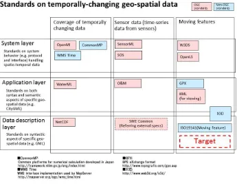
The OGC Moving Features encoding standard was developed to support the growing market for moving feature data. Figure 5.1 summarizes standards that can be used in temporally changing geospatial data applications. Many standards for coverage data and sensor observation data have been established and widely implemented. However, the only international standard for moving features is ISO19141:2008, which is defines an abstract model. OGC Moving Features was developed as an implementation standard based on ISO19141:2008.
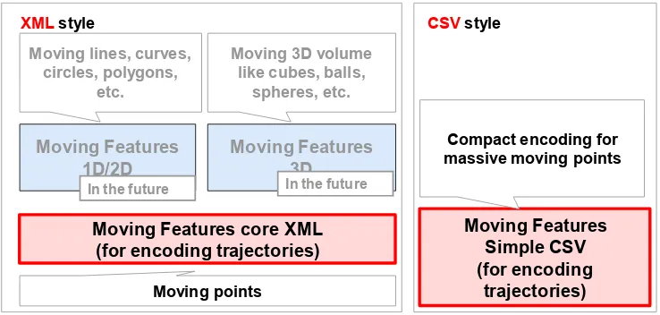
Figure 5.2 diagrams the modularity of the OGC Moving Features standard. Moving Features core XML is a fundamental standard designed for easy extensibility. Moving Features Simple CSV is encoding style designed to reduce data size even if large volumes of data are encoded. Moving Features 1D/2D and Moving Features 3D in the figure are standards for adding shapes of features to Moving Features core XML. They will be defined in a future version of the MF standard because most of existing use cases require only trajectory data without shapes.
Figure 5.2: Modularity of OGC Moving Features
5.1.1 Extensible Encoding Style: OGC Moving Features XML Core
The scope of the OGC Moving Features encoding is illustrated in Figure 5.3. The OGC Moving Features core XML standard defines an XML element to encode line-string like tracks. The other types of curves such as spline curve, constant acceleration, and circular movement will be defined as extensions in the future. Types of features in scope of the current Moving Features Simple CSV standard are constrained by the scope of Moving Features core XML. That is, Moving Features core XML can always encode features which are encoded by Moving Features Simple CSV.
Figure 5.3: Scopes of OGC Moving Features Encoding styles
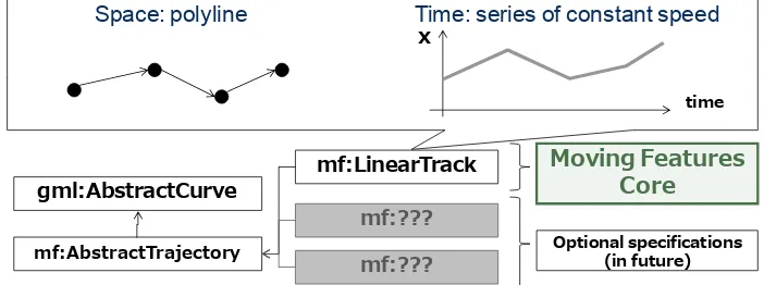
XML elements to describe trajectories are shown in Figure 5.4. mf:AbstractTrajectory is a fundamental superclass for all types of trajectories (as if gml:AbstractCurve with an attribute to specify the temporal interpolation). mf:LinearTrack is used for line-string like tracks.
Figure 5.4: Trajectory classes in Moving Features XML Core
Moving Features core <<trajectory>>
Moving Features 1D/2D
<<prism>> Extension, meta information etc.
Moving points, their
Space: polyline Time: series of constant speed
time
5.1.2 Simple Encoding Style: OGC Moving Features Simple CSV
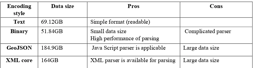
The OGC Moving Features Simple CSV standard was developed to reduce the size of moving features data encoded by OGC Moving Features core XML. Table 5.1 compares typical encoding styles. ‘Data size’ column lists roughly estimated data sizes in the table (600,000 features, 1440 points in a day for every feature). According to the comparison, data sizes by text and binary are half of that by JSON and XML. In addition, software to handle data encoded by the text style is easily developed. Text encoding style thus was developed as the first step.
Table 5.1: Rough estimation of data sizes
Encoding style
Data size Pros Cons
Text 69.12GB Simple format (readable)
Binary 51.84GB Small data size
High performance of parsing
Complicated parser
GeoJSON 184.9GB Java Script parser is applicable Large data size
XML core 164GB XML parser is available for parsing Large data size
5.1.3 Existing issues
The OGC Moving Features core XML standard defines a model to encode moving features. The OGC Moving Features Simple CSV standard was developed for practical and compact encoding. The functions provided by the standards satisfy requirements for simple use cases. Moreover, the following standards will enable more types of applications:
Binary encoding for larger datasets
6 Applications
6.1 Transportation survey with smart phones
Traffic congestion is a serious problem in many large cities. To solve such problems, two types of solutions are generally applied: road-construction and public transportation enhancements. Either solution requires travel demand data, which is the number of movements between places. This is because roads and public transportation should make connection between pairs of places with the highest trip demand. Therefore, travel demand data are collected using transportation surveys.
Questionnaires are traditionally used for the trip generation data collection. However, with the broad availability of location enabled mobile devices, GPS based data collection of trip information is applicable as the alternative. In the latter case, the GPS tracks are encoded by using the Moving Features standard to enable sharing by many stakeholders such as local governments, bus companies, and so on.
Figure 6.1: Transportation Survey
Background map: ©Open Street Map
6.2 Layout design with LIDAR
LIDAR (Laser Imaging Detection and Ranging) is a technique useful for detecting and tracking pedestrians [2][3][4]. In this use case, a pedestrian-tracking system using LIDAR is used to understand pedestrian movement behavior in a large facility such as shopping malls and train terminals.
©Hitachi, Ltd.
Figure 6.2: Tracks in Exhibition Event (2013)
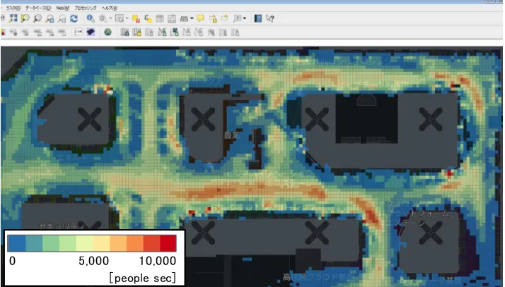
In Figure 6.1, pedestrian tracks obtained by LIDAR at a 2013 exhibition event are shown by the yellow lines. Such trajectory data are recorded and stored to a spatio-temporal database. The data can then be output as a data file encoded using the OGC Moving Features standard to send to another trajectory analysis system. Figure 6.2 shows population distribution of the pedestrian tracks, which was calculated by the trajectory analysis system. This population map can be calculated by counting the number of people in each grid.
©Hitachi, Ltd.
Figure 6.3: Population map (2013)
0 5 ,0 0 0 1 0 ,0 0 0
©Hitachi, Ltd.
Figure 6.4: Causal analysis
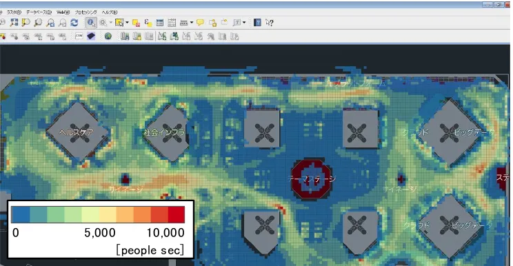
Popular booths could be determined by determining how many pedestrians at the event visited a booth and how long they stayed around the booth. Figure 6.3 illustrates the causal analysis to find such popular spots. As shown in the figure, flows of pedestrians should be bent by obstructions in order to make pedestrians stay at exhibition booths. According to the analysis, the exhibition event at the next year (2014) was designed to make more obstructions. Figure 6.4 shows a population map at 2014 as the result: pedestrian-dense areas are widely distributed to field of the event.
©Hitachi, Ltd.
Figure 6.5: Population map (2014)
O
Ob
b s
s t
t r
r u
uc
ct
ti
i o
on
n
Vi ew of
obst r uct ed
pedest r i a ns
Popula r pla ce
0 5 ,0 0 0 1 0 ,0 0 0
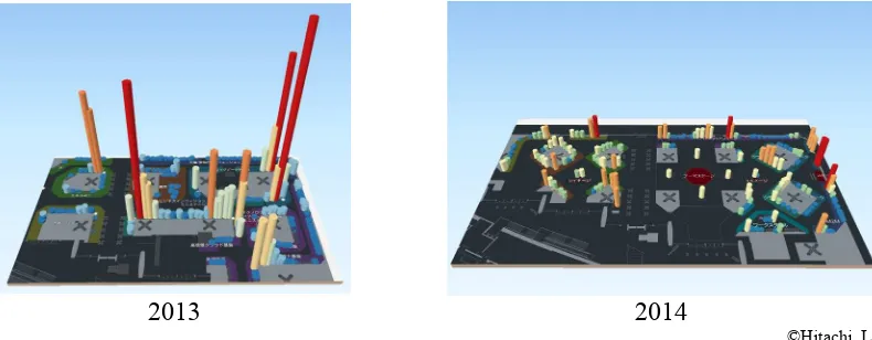
of cylinders. At a glance, it is confirmed that the durations of stay of visitors at 2014 were highly equalized in comparison to 2013.
2013 2014
©Hitachi, Ltd.
Figure 6.6: Contrast between “before” (2013) and “after” (2014)
The duration can be calculated by summing duration of trajectories around each booth, where a trajectory is “around a booth” if distance between the booth and the track is less than 3 meters.
6.3 Disaster Management
As an example of using MF for disaster management, an estimation system of tsunami damage partly implemented by the authors of this OGC Discussion Paper is introduced. A tsunami is a very large wave typically generated by a sudden up-thrust or sinking of the sea bed in association with an undersea earthquake, and causes serious damage along the coastal regions. Huge tsunamis have recently caused serious damage in Sumatra, Indonesia in 2004 and Tohoku, Japan in 2011. In order to reduce the amount of damage from tsunamis, measures and policies are required, such as the construction of breakwaters, the designation of evacuation areas, and the provision of evacuation guidance. A simulation for tsunami evacuation scenarios is helpful for creating measures and formulating policies.
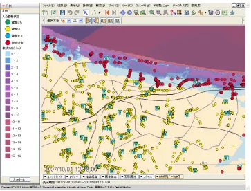
The simulation system for tsunami evacuation facilitates well-informed decision making for the appropriate allocation of tsunami evacuation buildings by integrating tsunami simulations and people flow or evacuation simulations. Tsunami simulations precisely estimate the flooded areas when a tsunami hits a coastal area. The estimation is based on the topography of the sea bed and land. The people flow or evacuation simulation
shot from the simulation system. The blue to purple color gradation indicates the height of the simulated tsunami. Each point denotes residents (a point for 50 people). The yellow points are evacuating people, while the red ones are people who could not escape. The green squares are tsunami evacuation buildings. The system requires the
functionality of exchanging temporally-changing inundation area/depth and moving features in a three-dimensional space.
For integrated simulation for disaster risk management, location data is collected and integrated from different simulation systems such as people evacuation simulations, road vehicle simulations including emergency vehicles, and tsunami simulations. Many of such location-based simulations, except the tsunami simulations, are agent-based simulation systems that explicitly output the trajectories of individual agents, i.e., pedestrians and vehicles. It is necessary to collect location data from cellular phones in order to increase accuracies of these simulations.
Figure 6.7: Example of Simulation of Evacuation from Tsunami for Coastal City
©Hitachi, Ltd.
6.4 Maritime sector use case
security within the maritime sector.
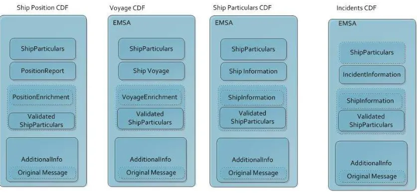
In order to address maritime use cases, the Moving Feature standard has to include at least the following information: (i) ship position, which can be provided by different data source (AIS, LRIT, etc …); and (ii) ship voyage, which describe the track of a ship. Additional information about the vessel incidents and the ship particulars has to be considered optional and therefore as possible extensions to the Moving Feature standard. For example, the following figure summarize the information collected by the Canonical Data Format produced by the European Maritime Safety Agency
Figure 6.8: Canonical Data Format
Figure 6.9: vessels positions map
A vessel has a unique identification at worldwide scale (IMO number, or MMSI). The position of a vessel (ship position) is a point feature over the time. The voyage feature of a vessel (ship voyage) is characterized by several attributes: speed over the water, course over the water, heading and true heading.
In conclusion, to build the trajectory of a vessel two main abstract feature types are relevant for Moving Feature standard: ship position and ship voyage.
6.5 Aviation sector use case
Aircraft and other airborne vehicles are moving features and the aviation sector has a (large) number of methods to track aircraft and to represent their position.
The main sources of tracking data include the following
Primary surveillance radar: Radar equipment measuring position and heading of aircraft.
Secondary surveillance radar: position detection is augmented with an active response from the aircraft’s transponder. It supplies additional information such as its identity.
for increasing air traffic capacity and safety.
Figure 6.10: Flight Management and Visualization (http://vimeo.com/133130574)
The position and related data of aircraft is encoded according to different standards. One standard is Eurocontrol ASTERIX (http://www.eurocontrol.int/asterix). ASTERIX
defines different categories. Most categories contain position data according to a different detection method.
For instance, category 48 defines the following fields (copied from the Cat 48 specification on http://www.eurocontrol.int/services/specifications-documents )
Data Item Description Description System Units I048/010 Data Source Identifier N.A.
I048/020 Target Report Descriptor N.A. I048/030 Warning/Error Conditions N.A.
I048/040 Measured Position in Slant Polar Co-ordinates
RHO: 1/256 NM, THETA: 360°/(2 16)
I048/042 Calculated Position in Cartesian Co-ordinates X, Y: 1/128 NM I048/050 Mode-2 Code in Octal Representation N.A.
I048/080 Mode-3/A Code Confidence Indicator N.A. I048/090 Flight Level in Binary Representation 1/4 FL I048/100 Mode-C Code and Confidence Indicator N.A. I048/110 Height Measured by a 3D Radar 25 ft I048/120 Radial Doppler Speed (2-14) NM/s I048/130 Radar Plot Characteristics N.A.
I048/140 Time of Day 1/128 s
I048/161 Track/Plot Number N.A.
I048/170 Track Status N.A.
I048/200
Calculated Track Velocity in Polar Representation
Speed: (2-14) NM/s, Heading:360°/(2 16)
I048/210 Track Quality N.A.
I048/220 Aircraft Address N.A.
I048/230
Communications / ACAS Capability and Flight
Status N.A.
I048/240 Aircraft Identification N.A.
I048/250 Mode S MB Data N.A.
I048/260 ACAS Resolution Advisory Report N.A.
The items in bold relate to the position, heading, time, and identity of the aircraft. Other information fields provide metadata on quality, data source, etc.
Other ASTERIX categories provide different sets of information where position and other information may also be encoded in different ways. Some interesting aspects of ASTERIX:
The positions may be expressed in relation to the radar equipment position. A (separately available) position of the radar is thus needed to correctly geo-reference the aircraft.
The data has a binary encoding optimized to obtain a small message size. Verbose GML/XML/JSON encoding may be a barrier for adoption of the Moving Feature standard for large data sets in the aviation world.
Many data sets do not include all fields. Optional elements in the Moving Features may accommodate representing such data sets.
http://www.fly.faa.gov/ASDI/asdi.html for more information.
In order to address aviation use cases at least this information must be managed in the Moving Feature standards. Other information is important as well and may be encoded as use-case specific metadata.
Use cases can also involve analysis afterwards (incident analysis, statistics, etc.) or simulated air traffic. The Moving Features standard may be useful to convert raw feeds into a standard moving features representation for use in generic analysis and processing tools.
6.6 Moving Feature Use case for Hurricanes
Tropical storms, hurricanes and typhoons are extremely energetic and dangerous weather phenomena with a pronounced centre of rotation, the 'eye'. Their position can be forecast, with increasing accuracy, several days in advance, and even more accurately only a day in advance. These forecasts are normally presented to the general public and emergency services as a simple graphical map, often using PNG or JPEG formats.
Hurricanes and typhoons are the same phenomenon. Traditionally the names for these phenomena in the western Pacific and western Atlantic are different. A tropical storm is a weaker version, causing less damage, but can become more energetic and become a hurricane/typhoon. Currently a wind speed threshold of 65 knots (120Km/hour, 75 miles/hour) is the only distinguishing attribute.
Typically a deterministic chart will show a single forecast storm trajectory as a single track with the location of the storm centre or 'eye' indicated at regular intervals, say every 6 or 12 hours. The location at a specific time is usually marked by specific symbols, standardized across all countries for both meteorology and aviation.
Sometimes a probabilistic chart is preferred, and a range of possible trajectories or an envelope of these trajectories is used. The set of trajectories may come from a single forecast centre using an ensemble of possible forecasts, or the set may be from several forecast centers which all produce slightly different forecasts. Generally, if the spatial, and temporal, spread of the set of trajectories is small, then more confidence is attached to them than if the spread is great.
Expert users, such as forecasters, may also use a chart that displays ranges of trajectories from successive forecast times, and the actual trajectory so far. Again, similarity in these successive forecasts gives increased confidence in the accuracy of the forecasts.
If graphical output is inappropriate, there is a standardized simple text message used to transmit the current and forecast locations across emergency communications channels. These messages also include the actual and forecast wind speeds at various distances and directions from the 'eye'. The atmospheric pressure near the eye may also be included. The central pressure is an important indicator of damage, like the wind speed, as the reduced pressure causes the local sea surface to rise by a few meters, causing flooding and destructive waves.
The sea surface temperature in the path of the storm is also important, as this determines whether the storm will increase or decrease in strength.
on map
Goal: To replicate the conditions under which crime is committed and predict crime patterns, for example predicting regions more vulnerable to crime based on Routine Activity Theory.
Setup: Criminals tend to move only along roads on the map. There are certain fixed marked spots on the map. These include Criminal's Home, Office, Mall, Bar, Restaurants. There is a weekly schedule and the criminal agent moves between these spots based on the schedule.
Forms of Motion:
Beeline Movement: The criminal agent chooses one of the shortest 3 paths between two spots randomly and moves along it. This is time bound - if there are less than 3 routes that can be covered in the amount of time the agent has - only that number of routes are considered for random selection.
Random Movement: Agent starts from source and at each road intersection. Agent chooses a road randomly and moves along it. This is also time bound - when time runs out, the agent moves to the destination along the shortest path from its current location.
Hybrid Movement: Agent moves between source and destination along the shortest path with deviations. Agent randomly chooses two points on the shortest route and takes a longer different route between these two points. If there is time remaining, agent repeats this, otherwise moves to the destination along the shortest path.
Prediction of Crime Patterns: Criminal Agent, Victim Agents and Police all keep moving along the map as per their schedules. There are a number of designated crime spots on the map. When the criminal agent passes through the vicinity of a crime spot, they decide whether or not to commit crime based on factors like profit value associated with crime spot, risk involved, presence of police nearby, absence of guardian of spot and the
number of times the spot has been visited before. Crime Patterns are predicted by running this simulation a very large number of times.
Discussion:
The simulation needs a city description with roads and buildings of interest. CityGML could be used here.
The trajectory is repeated weekly with random variations. That may be represented as a "base line" moving feature. This base line would not describe a real moving feature, but would be used as a template.
Interactions between the environment (CityGML) and the moving features may trigger events. For example when <mf:Trajectory> value become close to a
CityGML feature or interest having a low "presence of police" attribute, a crime may occur depending on the value of that attribute and other attributes like "absence of guardian", "profit", and "risk".
Example: The criminal agent moves between Home, Office, Bar, Lunch-A, Lunch-B, Mall marked on the map as per a weekly schedule. The result corresponds to the weekly schedule run for 500 times on the city: Indianapolis. The small squares on the map correspond to crime spots. The color of each crime spot represents the number of times crime has been committed at that spot, normalized on a scale of 0-100.
Background: It is an important task of soccer coaches to analyze completed matches for developing proper tactics and preparing for future matches. With recent progress in several video analysis and sensor technologies, it is now possible to gather match data including trajectories of both players and the ball.
Feature Modelling [5]: A soccer match is composed of 23 moving features including 22 players and ball, where each moving feature has p(x,y) or p(x,y,z) coordinates for each time instance during a match. A sequence of moving point for a player or ball forms a trajectory. A basic feature model for soccer match in terms of moving feature is given as the following figure.
Figure 6.14: Basic Feature Model for Soccer Match
We define two abstract feature types Point Feature and Point Trajectory Feature as the root classes of the model of figure 1, which correspond to spatial and spatiotemporal objects respectively. And Ball and Player, which inherit from Point Feature, have the coordinates of the ball and players at each sampling time instance. Ball Trajectory and
Collective Trajectory. We may define additional properties for player such as direction.
Based on the information of this basic feature model, we can derive more useful
information from primitive behaviors such as kicks, ball possession, dribbles (see figure 2), intercepts, passes, to complicated strategies such as formation, defense or attack systems.
Figure 6.15: Dribbles [6]
6.9 Real-time location data collection
Collecting real time location data is important for some use cases. This use-case presents system architecture, operations, operation sequence for collecting location data in real-time.
6.9.1 System architecture
Figure 6.16: System architecture for collecting location data
Sensor - Entity that provides data of an observed property as output.
Sensor System - System which multiple sensors compose.
Location data aggregator - Entity that receives location data from sensor systems and sends location data to location data receivers.
Location data receiver - Entity that receives location data from location data aggregators.
6.9.2 Operations
RegisterSensor – an operation for registering information of a sensor system to a location data aggregator. The data aggregator deletes the information of a sensor system when it receives an empty RegisterSensor message from the sensor system.
InsertTrajectory – an operation for sending location data to an location data
aggregator. The location data aggregator sends the location data to location receivers.
6.9.3 Operation sequence
6.9.3.1Registration for sensor system
6.9.3.2Registration for location data receiver
1. The Location data receiver sends a request for registration as a subscriber of topic “lcp/RegisterSensor/#” to location data aggregator. “#” is a wild card in topic definition of MQTT.
2. The Location data aggregator registers the location data receiver. 3. The Location data aggregator sends the latest message of topic
“lcp/RegisterSensor/#”. This message includes sensor system IDs and schema definitions generated by the sensor systems.
4. The Location data receiver sends a request for registration as a subscriber of topic “lcp/InsertTrajectory/[SensorSystemID]”
5. The Location data aggregator registers the location data receiver. 6.9.3.3Sending and receiving location data
1. The sensor system sends location data encoded by OGC Moving Features Simple CSV data body to a location data aggregator on topic “lcp/InsertTrajectory/ [SensorSystemID]”.
2. The Location data aggregator sends the location data to subscribers of topic “lcp/InsertTrajectory/[SensorSystemID]”.
6.9.3.4Sending and receiving location data
1. The sensor system sends a message with an empty content to the location aggregator on topic “lcp/RegisterSensor/[SensorSystemID]”.
The Location data aggregator sends the message to subscribers of “lcp/RegisterSensor/[SensorSystemID]”.
Acknowledgement
7.1 Needs for “OGC Moving Features API”
Based on the use cases and applications for OGC Moving Features as described in Clause 6 above, the following API operations are needed:
1. Retrieval of feature information
For examples, these operations retrieve positions, trajectories, and velocities of a moving feature such as a car (see Clauses 6.1, 6.3, 6.7, and 6.8), a person (see Clauses 6.2 and 6.3), a vessel (see Clause 6.4), an aircraft (see Clause 6.5), and a hurricane (see Clauses 6.6).
2. Operations between MF_TemporalTrajectory and GM_Object
An example of these operations is “intersection” between a geometric object and a trajectory of a moving feature like a car (see Clauses 6.1, 6.3, 6.7, and 6.8), a person (see Clauses 6.2 and 6.3), a vessel (see Clause 6.4), an aircraft (see Clause 6.5), and a hurricane (see Clauses 6.6).
3. Operations between two MF_TemporalTrajectory
An example of these operations is to calculate a distance of the nearest approach of a trajectory to another trajectory. The case studies are distance between a criminal agent and a police agent for predicting crime patterns (see Clause 6.7) and distance between soccer players for making proper tactics (see Clause 6.8).
Therefore, the Moving Features SWG recommends that a new Moving Features API standard supporting these operations should be defined. Figure 7.1 summarizes existing APIs and Moving Features API. Operations for geometric objects have been supported by OGC 06-103r4 (OpenGIS Implementation Standard for Geographic information - Simple feature access - Part 1: Common architecture) and ISO 13249-3 (Information technology — Database languages — SQL multimedia and application packages Part3: Spatial). On the other hand, a part of operations for trajectories was defined by ISO 19141:2008, which is an abstract specification for moving features. Thus, the new Moving Features API should target the following three kinds of operations: retrieval of feature information (“Target A” shown in Figure 7.1), operations between a trajectory and a geometric object (“Target B” shown in Figure 7.1), and operations between two trajectories (“Target C” shown in Figure 7.1). Collection operations, of which targets are collection data, such as clustering of multiple trajectories, obtaining centroid of multiple trajectories are
Figure 7.1: Existing APIs and Moving Features API
Examples of Moving Features APIs are shown in Clauses 7.2, 7.3, 7.4, and 7.5. In these examples, MF_TemporalTrajectory and GM_object deal with 2 or 3 dimensional objects.
7.2 Target A – 1. retrieval of feature information
The operations on retrieval of feature information are based on operations of “MF_TemporalTrajectory” (see ISO19141:2008).
pointAtTime – accepts a time in the domain of the trajectory as input, and returns the direct position of the trajectory at that time.
MF_TemporalTrajectory::pointAtTime(t: TM_GeometricPrimitive): DirectPosition
timeAtPoint – accepts a direct position as input and returns the set of times at which the trajectory passes through that direct position.
MF_TemporalTrajectory::timeAtPoint(p: DirectPosition): Set<TM_GeometricPrimitive>
velocity – accepts a time as input and returns the velocity as a vector at that time.
MF_TemporalTrajectory::velocity(t: TM_Coordinate): Vector
timeToDistance – returns a graph of the time to distance function as a set of curves in the Euclidean space consisting of coordinate pairs of time, distance.
MF_TemporalTrajectory::timeToDistance( ): GM_Curve[1..*]
timeAtDistance – returns an array of TM_GeometricPrimitive that lists in ascending order the time or times a particular point (determined by the Set<Distance> in the trajectory’s GM_GenericCurve::paramForPoint(p:DirectPosition) : Set<Distance>, DirectPosition) is reached.
MF_TemporalTrajectory::timeAtDistance(d: Distance): TM_GeometricPrimitive[0..*]
cummulativeDistanceAtTime – accepts a time as input and returns the cumulative distance travelled (including all movements forward and retrograde as positive travel distance) from the beginning of the trajectory at that time “t”.
MF_TemporalTrajectory::cumulativeDistanceAtTime(t: TM_Coordinate): Distance
timeAtCummulativeDistance – accepts a distance as input and returns the time at which the trajectory’s total length (including all movements forward and retrograde as positive travel distance) reaches that cumulative travel distance.
MF_TemporalTrajectory::timeAtCumulativeDistance(d: Distance): TM_GeometricPrimitive
subTrajectory – accepts two times in the domain of the trajectory and return a trajectory that is a subset of the given trajectory for the specified time interval.
MF_TemporalTrajectory::subTrajectory(newStartTime: TM_Coordinate, newEndTime: TM_Coordinate): MF_TemporalTrajectory
positionAtTime – accepts a time in the domain of the trajectory and return the position of the moving feature on the trajectory at that time, expressed as a liner reference system position.
MF_TemporalTrajectory::positionAtTime(t: TM_Coordinate): LR_PositionExpression
7.3 Target B – 2. relations between MF_TemporalTrajectory and GM_Object
equals – accepts a point object and a time interval as input and returns 1 (TRUE) if this trajectory “spatially equal” to the point object. The parameter “timeInterval” shall restrict the search to a particular period of time.
MF_TemporalTrajectory::equals(p: GM_Point, timeInterval: TM_Period): Interger
disjoint – accepts a geometric object and a time interval as input and returns 1 (TRUE) if this trajectory “spatially disjoint” from the geometric object. The parameter “timeInterval” shall restrict the search to a particular period of time.
MF_TemporalTrajectory::disjoint(geometry: GM_Object, timeInterval: TM_Period): Interger
intersects – accepts a geometric object and a time interval as input and returns 1 (TRUE) if this trajectory “spatially intersects” the geometric object. The parameter “timeInterval” shall restrict the search to a particular period of time.
MF_TemporalTrajectory::intersects(geometry: GM_Object, timeInterval: TM_Period): Interger
distanceWithin— accepts a geometric object, a time interval and a distance as input and returns 1 (TRUE) if this trajectory and the geometric object are within the specified distance of one another. The parameter “timeInterval” shall restrict the search to a particular period of time.
MF_TemporalTrajectory::distanceWithin(geometry: GM_Object, timeInterval: TM_Period, d: Distance): Interger
intersection — accepts a geometric object and a time interval as input and returns a sub-trajectory that represents the intersection of this trajectory to the geometric object. The parameter “timeInterval” shall restrict the search to a particular period of time.
MF_TemporalTrajectory::intersection(geometry: GM_Object, timeInterval: TM_Period): MF_TemporalTrajectory
difference — accepts a geometric object as input and returns a sub-trajectory that represents the difference of this trajectory from the geometric object. The parameter “timeInterval” shall restrict the search to a particular period of time.
MF_TemporalTrajectory::difference(geometry: GM_Object, timeInterval: TM_Period): MF_TemporalTrajectory
timeInterval: TM_Period): Distance, TM_GeometricPrimitive[1..*]
nearestApprochPoint — accepts a geometric object as input and returns a set of times and a direct position of the nearest approach of this trajectory to the geometric object (see Figure 7.2). The parameter “timeInterval” shall restrict the search to a particular period of time.
MF_TemporalTrajectory::nearestApproachPoint(geometry: GM_Object, timeInterval: TM_Period): DirectPosition,TM_GeometricPrimitive[1..*]
snapToGrid — accepts a point object (origin) and an array whose elements are two cell sizes (x and y cell sizes) or three cell sizes (x, y, and z cell sizes) for a grid as input and returns a trajectory snapped to the grid.
MF_TemporalTrajectory::snapToGrid(p: GM_Point, cellsize[]: float): MF_TemporalTrajectory
Figure 7.2: nearestApproach and nearestApproachPoint
between a trajectory and a geometric object
7.4 Target C – 3. relations between two MF_TemporalTrajectory
equals – accepts another trajectory and a time interval as input and returns 1 (TRUE) if this trajectory “spatially equal” to the other trajectory. The parameter “timeInterval” shall restrict the search to a particular period of time.
MF_TemporalTrajectory::equals(anotherTemporalTrajectory: MF_TemporalTrajectory, timeInterval: TM_Period): Interger
disjoint – accepts another trajectory and a time interval as input and returns 1
(TRUE) if this trajectory “spatially disjoint” from the other trajectory. The parameter “timeInterval” shall restrict the search to a particular period of time.
MF_TemporalTrajectory::disjoint(anotherTemporalTrajectory: MF_TemporalTrajectory, timeInterval: TM_Period): Interger
intersects – accepts another trajectory and a time interval as input and returns 1 (TRUE) if this trajectory “spatially intersects” the other temporal trajectory. The parameter “timeInterval” shall restrict the search to a particular period of time.
MF_TemporalTrajectory::intersects(anotherTemporalTrajectory: MF_TemporalTrajectory, timeInterval: TM_Period): Interger
distanceWithin— accepts another trajectory a time interval, and a distance as input and returns 1 (TRUE) if this trajectory and the other trajectory are within the distance of one another. The parameter “timeInterval” shall restrict the search to a particular period of time.
MF_TemporalTrajectory::distanceWithin(anotherTemporalTrajectory: MF_TemporalTrajectory, timeInterval: TM_Period, d: Distance): Interger
intersection — accepts another trajectory and a time interval as input and returns direct points that represent the intersection of this trajectory and the other trajectory. The parameter “timeInterval” shall restrict the search to a particular period of time.
MF_TemporalTrajectory::intersection(anotherTemporalTrajectory:
MF_TemporalTrajectory, timeInterval: TM_Period): Set<DirectPosition>
nearestApproach — accepts another trajectory and a time interval as input and returns a set of times and a distance of the nearest approach of this trajectory to the other trajectory (see Figure 7.3). The parameter “timeInterval” shall restrict the search to a particular period of time.
MF_TemporalTrajectory::nearestApproach(anotherTemporalTrajectory: MF_TemporalTrajectory, timeInterval: TM_Period): Distance,
TM_GeometricPrimitive[1..*]
period of time.
MF_TemporalTrajectory::nearestApproachPoint(anotherTemporalTrajector y: MF_TemporalTrajectory):directPosition,TM_GeometricPrimitive[1..*]
Figure 7.3: nearestApproach and nearestApproachPoint
between two temporal trajectories
7.5 Collection operations
The input of the operations classified into this category is multiple trajectories. For example, this category includes clustering of multiple trajectories, obtaining centroid of multiple trajectories, and so on. This category is positioned as future works until the demands are clarified.
7.6 Concluding remarks
Bibliography
[1] Guidelines for Successful OGC Interface Standards, OGC document 00-014r1
[2] K. Nakamura. H. Zhao. R. Shibasaki. K. Sakamoto. T. Ooga. and N. Suzukawa, “Tracking Pedestrians by using Multiple Laser Range Scanners”, ISPRS
commission IV WG IV/1 XXth ISPRS Congress. 2004, Jul-04
[3] M. Hashimoto, T. Konda, B. Zhitao and K. Takahashi, “Laser-based tracking of randomly moving people in crowded environments”, 2010 IEEE International Conference on Automation and Logistics (ICAL), pp 31-36
[4] K. Schenk, M. Eisenbach, A. Kolarow, H. M. Gross, “Comparison of Laser-Based Person Tracking at Feet and Upper-Body Height”, KI 2011: Advances in
Artificial Intelligence, Vol. 7006, 2011, pp 277-288
[5] Ho-Chul Kim, Oje Kwon and Ki-Joune Li, "Spatial and Spatiotemporal Analysis of Soccer", Proceedings of ACM SIGSPATIAL GIS ’11, November 1-4, 2011. Chicago, IL, USA
Revision history
Date Release Editor Primary clauses modified
Description
5/21/2015 Carl Reed Numerous Editorial changes and suggestions 5/22/2015 Akinori
Asahara
6.3, 6.8 and bibliography
The bibliography was listed at the end of this paper
7/30/2015 Hideki Hayashi
7 The API description was revised
9/11/2015 Frederic Houbie
6.5 Two additional images
10/6/2015 Akinori Asahara
Title Title: “Search as used in Applications of OGC Moving Features”