A CITYGML EXTENSION FOR HANDLING VERY LARGE TINS
K. Kumar∗, H. Ledoux, J. Stoter
3D Geoinformation, Delft University of Technology, The Netherlands - (k.kavisha, h.ledoux, j.e.stoter)@tudelft.nl
KEY WORDS:CityGML, GML, Terrains, TINs.
ABSTRACT:
In addition to buildings, the terrain forms an important part of a 3D city model. Although in GIS terrains are usually represented with 2D grids, TINs are also increasingly being used in practice. One example is 3DTOP10NL, the 3D city model covering the whole of the Netherlands, which stores the relief with a constrained TIN containing more than 1 billion triangles. Due to the massive size of such datasets, the main problem that arises is: how to efficiently store and maintain them? While CityGML supports the storage of TINs, we argue in this paper that the current solution is not adequate. For instance, the 1 billion+ triangles of 3DTOP10NL require 686 GB of storage space with CityGML. Furthermore, the current solution does not store the topological relationships of the triangles, and also there are no clear mechanisms to handle several LODs. We propose in this paper a CityGML extension for thecompactrepresentation of terrains. We describe our abstract and implementation specifications (modelled in UML), and our prototype implementation to convert TINs to our CityGML structure. It increases the topological relationships that are explicitly represented, and allows us to compress up to a factor of∼25 in our experiments with massive real-world terrains (more than 1 billion triangles).
1. INTRODUCTION
A 3D city model is a digital representation of the geographical objects within a city (Stadler and Kolbe, 2007). At first, 3D city models were mainly used for visualization, but with the advance-ments in geoinformation technologies, they have gained impor-tance in different domains like urban planning, 3D cadastre, en-vironmental simulations, etc.; see Biljecki et al. (2015) for an overview. It should be noticed that, so far, the applications of 3D city modelling are mostly centred around the buildings; other fea-tures, e.g. terrain/relief, vegetation, roads, water bodies, bridges, are often ignored. We focus in this paper on the terrain part of a 3D city model, and particularly on its storage as a TIN (Trian-gulated Irregular Network), which is, apart from grids, more and more used in practice. TINs are a network of non-overlapping tri-angles formed by the interconnection of irregularly spaced points (Kumler, 1994). They are generally constructed using Delaunay triangulation but this is not always true (Rippa, 1990; Dyn et al., 1990). Everytime the typical inputs for TIN construction are not only a set of vertices but can include other constraints like seg-ments or polygons, etc.In such cases, a constrained triangulation can be constructed. A CDT (Constrained Delaunay Triangula-tion) is like DT however every given input segment appears as an edge in the triangulation (Shewchuk, 1996).
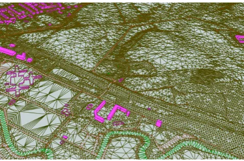
While the international standard CityGML (City Geography Mark-up Language) allows us to store terrains as TINs (with and with-out constraints) (OGC, 2012), we argue in this paper that the current solution is not suitable to store massive TINs. Firstly, with massive TINs, the datasets become very large, which greatly hinders exchange and dissemination. Secondly, there is very lit-tle topological information stored, which prevents us from using the triangles for analysis. The cause of these two problems are that triangles are stored with the OGC Simple Feature structure, which stores independently each triangle, and moreover repeats several vertices. We discuss in Section 3 the other limitations of the current solutions. As an example, consider 3DTOP10NL, the 3D city model of Netherlands (Kadaster, 2015), which cov-ers the whole country, including buildings, terrain, roads, canals, etc. (see Figure 1). It is constructed by adding the third
dimen-∗Corresponding author
Figure 1: An area of the 3DTOP10NL dataset. Notice that the terrain, the roads, the water courses have all been triangulated, forming one large triangulation for the whole of the Netherlands.
sion from a point cloud, obtained from airborne laser-scanners, to the objects in the 2D topographic map TOP10NL (Elberink et al., 2013). Its terrain is a constrained TIN with more than 1 billion triangles (1,156,641,666 to be exact). Storing it with the current solution of CityGML requires around 686 GB of storage space. One can imagine that if all the elevation points from the point cloud had been used (around 640 billions, thus around 1.3 trillion triangles), then the file size would clearly prevents us from using the dataset.
TINs to our CityGML extension structure. This allows us to com-press up to a factor of∼25 massive real-world terrains such as the 3DTOP10NL.
2. TERRAINS IN CITYGML
CityGML is an XML based data model for the storage and ex-change of virtual 3D city models (Groger et al., 2012). It is imple-mented as an application schema of GML3 (Geography Markup Language version 3.1.1) and models 3D geometry along with semantics. The data model of CityGML comprises of a core module and several thematic extension modules likeBuilding, Relief, Bridge, LandUse, Tunnel, Vegetation,
Water-Body, etc.(Groger et al., 2012). Here we consider the terrain
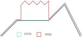
as a DTM (Digital Terrain Model). In practice, the terms DTM and DSM (Digital Surface Model) are often assumed to be syn-onymous. Before going further, the terms DTM and DSM should be clear. DTM depicts the surface of the earth without any re-lief objects i.e. the bare earth (shown in blue in Figure 2). DSM depicts the surface of the earth including the relief objects on it (shown in red in Figure 2).
DTM DSM
Figure 2: Digital Terrain Model
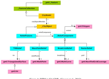
In CityGML, DTM is provided by the thematic moduleRelief (Groger et al., 2012). The features of the terrain are represented by the classReliefFeature. The terrain can be represented ei-ther as a TIN(TINReflief), or as a Grid(RasterRelief), or as masspoints(MasspointRelief), or as breaklines
(Break-lineRelief)(Figure 4). The corresponding GML3 classes are:
gml:RectifiedGridCoveragefor grids,gml:MultiCurvefor
break lines,gml:MultiPointfor mass points and
gml:Trian-gulatedSurfaceorgml:Tinfor TINs (Groger et al., 2012). It
is also possible to represent terrain as a combination of differ-ent terrain types within a single dataset. For instance, terrain can be modelled by a coarse grid with some areas of detailed TIN (Figure 3) or a TIN with break lines to depict a constrained tri-angulation, etc. The validity of each terrain type is limited to a certain area defined by thevalidity extent polygon.
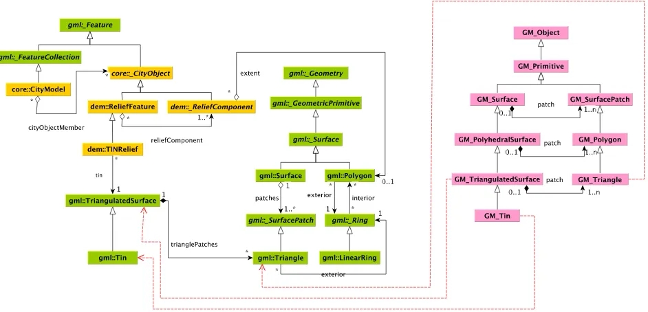
A TIN in CityGML is stored as a set of linear rings with
gml:Tri-anglegeometry (Figure 5). The classTINReliefdescribes a
terrain as a triangulated surface embedded in 3D space. Its geom-etry is specified by the GML classgml:TriangulatedSurface, which is composed of triangles explicitly specified as
triangle-Patcheswithgml:Trianglegeometry (Figure 6). Within its
subclassgml:Tin, only the points (with 3D coordinates) are rep-resented, along with optional breaklines (which acts as constraints in the triangulation (Shewchuk, 1997)), control points, etc. The support for TINs in GML3 as Linear Rings is consistent with OGC Geometry Abstract Specifications, ISO 19107:2003 Spatial schema and OGC Simple Feature Common Architecture (OGC, 2011). The ISO 19107:2003 Spatial schema specifies the con-ceptual schema for representing and manipulating TINs in com-pliance with ISO 19103. These abstract specifications are imple-mented in ISO 19136 GML. GML is an XML encoding (as per ISO 19118) for the storage and exchange of geoinformation (both spatial and non-spatial attributes of spatial features). The geoin-formation is modelled according to the conceptual schemas used in ISO 1900 series.
T IN Relief
Grid Coverage validity polygon
Figure 3: TIN + Grid combination in CityGML. TIN vertices may lie anywhere on the grid and not necessarily at the centre of each grid pixel.
It should be noticed that if only the points of the TIN are stored (and not the triangle), then the triangulation that is calculated with a given triangulator in a downstream application might not always be same. Indeed, the Delaunay triangulation has the property of being unique, but that is only if no four points are co-circular. In practice, this is virtually never the case, especially since many ter-rain data come from grids where by definition each four points of a cell are co-circular. There exists different algorithms to ensure that a list of points always yield the same Delaunay triangulation: Edelsbrunner and M¨ucke (1990) use the ordering of the points, and Dyken and Floater (2006) define preferred directions. How-ever, if one stores only their points, there is no guarantee that the algorithm used by the practitioner will have these properties. The problem is made worse when a constrained Delaunay triangula-tion (CDT) is used, since the algorithms to construct these from points and breaklines are less common and standardised.
3. PROBLEMS IN STORING MASSIVE TERRAINS IN CITYGML/GML
CityGML supports the storage of terrains as TINs and Grids. However, there are several problems associated with the storage of massive terrains in CityGML format.
1. Huge data volumes: Since every triangle is stored as a lin-ear ring of vertices (Figure 5), the size of the CityGML files is increased considerably with the repeated storage of ver-tex information. In a 2D Delaunay triangulation the average degree of a vertex is 6 if the vertices follow a Poisson distri-bution (Okabe et al., 2009). This suggests that on an average each vertex is stored 6+6/3 = 8 times thereby, increasing the vertex information redundancy in the CityGML datasets.
2. No topology: There is no storage of topological information of TIN. The triangles are stored individually irrespective of their neighbours. This hinders spatial analysis greatly.
3. No referencing of triangles and their vertices: There is no referencing scheme for the vertices of a triangle. Each tri-angle is specified with a list of coordinates of its vertices in full which takes more space (Figure 5). There is no indexing of triangles as well.
Figure 4: DTM in CityGML (Groger et al., 2012)
(x1, y1, z1)
(x2, y2, z2) (x3, y3, z3)
< gml:triangle > < gml:exterior >
< gml:LinearRing >
< gml:posList > x1y1z1x2y2z2x3y3z3x1y1z1< /gml:posList > < gml:LinearRing >
< gml:exterior > < gml:triangle >
Figure 5: OGC Simple Feature
4. Badly modelled TIN geometry: The class
gml:Triangula-tedSurfacecomprises of triangle patches forming the TIN.
It is defined as a separate subclass of gml:Surface but it could have been defined as a subclass of
gml:Composite-Surface. A composite surface requires its elements to be
disjoint, not to have overlapping interiors and must be topo-logically connected along their boundaries. These prerequi-sites are fulfilled in case of TINs.
5. No specifications for terrain LODs: There is no distinction between different LODs of a terrain in CityGML at geomet-rical and semantic level. The CityGML 3.0 provides ex-tended LODs for theBuildingmodule only and the LOD specifications of other modules like Relief, etc. are left out as unessential features (L¨owner et al., 2013; Gr¨oger and L¨owner, 2016). Giving only agml:loddoes not solve the issue if we cannot identify the difference between LODs.
6. Vertical triangles are not handled: 3DTOP10NL has the skeletons of the urban objects like buildings, roads, etc. in-tegrated in the terrain. In a way, it is not completely a 2.5D but a 2.8D model with vertical walls. A 2.8D models is a 2-manifold surface embedded in a 3D space (Gr¨oger and
Pl¨umer, 2005). When a 2.8D model is projected on a 2D sur-face, the vertical surfaces flatten out which distorts the ge-ometry of the model. There is no mechanism in CityGML to mark out these vertical surfaces so as to remove them while transforming from 3D to 2D.
7. No support for Tiling: The main memory of a system plays a key role in deciding the maximum size of a dataset that can be processed (Isenburg et al., 2006). If the size of the datasets exceeds the available memory limit then it is split into small parts (calledtiles). The concept of tiling the TIN cannot be extended to CityGML as there can be triangles spanning several tiles. Such triangles are repeated in the spanned tiles to complete the OGC SF closed linear ring structure thereby causing information redundancy in the City-GML datasets (Kumar et al., 2016).
8. Unclear TIN and Grid combination : Though CityGML documentation (Groger et al., 2012) describes having a com-bination of multiple terrain types in a single CityGML in-stance. But, there can be problems of mismatch of geometry when it comes to combining a TIN and a Grid for a terrain dataset. For instance, in Figure 3, the terrain is represented by a grid along with a certain area represented by a TIN. The TIN vertices may lie anywhere on the grid and not nec-essarily at the centre of each grid pixel. Deriving the exact value of elevation of TIN vertices from grid pixels can be an expensive operation in this case.
Figure 6: TINs in CityGML and ISO 19107:2003 Spatial schema
web visualization is the rate at which these triangles can be rendered over the graphics engine.
4. PROPOSED SOLUTION: TERRAINS@CITYGML
Figure 7: Workflow for proposed solution. CityGML/GML are extented to store terrain geometry and semantics as proposed.
4.1 Terrains@CityGML
Based on the weaknesses of the current CityGML/GML schema in storing massive terrains (as highlighted in Section 3), we pro-pose an alternative representation to represent TINs,
Terrains@-CityGML. Terrains@CityGML is modelled as an extension to
CityGML constructed by adding new geometry encoding schemes for TINs in the CityGML/GML schema. CityGML has the con-cept ofADEs to extend the schema with new classes/attributes which are not explicitly modelled in CityGML. ADEs are in-creasingly being used in creating application-specific extensions like for energy modelling (Nouvel et al., 2015), BIM-IFC in-tegration with CityGML (de Laat and Van Berlo, 2011), IM-Geo for modelling Dutch topographic data in CityGML (Brink et al., 2013), indoor modelling (Kim et al., 2014), noise mod-elling (Groger et al., 2012), etc. Similarly, there are many spe-cialized versions of GML. For instance,FieldGMLis GML based
implementation for the representation of geofields in 2D and 3D (Ledoux, 2008). Another GML based implementation is NcML-GMLwhich provides for storing the metadata of netCDF files in GML (Nativi et al., 2005). Others includeCSML(Woolf et al., 2006),GeoSciML(Sen and Duffy, 2005), etc.
Terrains@CityGMLis introduced as an ADE for handling very
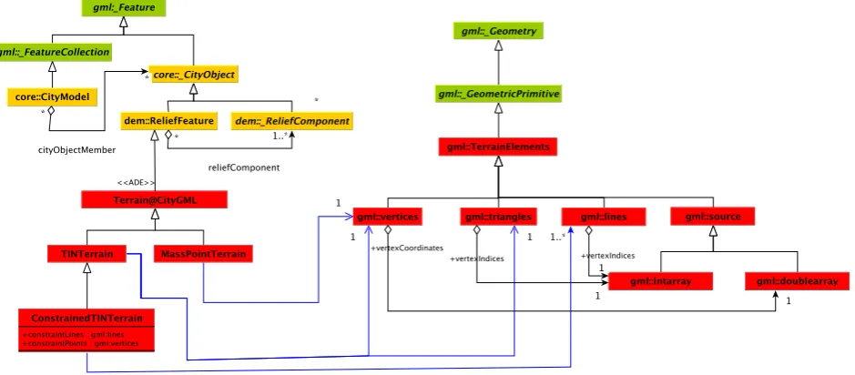
large TIN representation of terrains in CityGML. The new classes and attributes for terrain semantics and geometry are defined in the schema. The workflow for the proposed solution is depicted in Figure 7. Figure 8 shows the basic class diagram for the pro-posed Terrains@CityGML. Two new types, TINTerrainand
MassPointTerrainfor compactly storing the terrains are
de-fined which are capable of storing terrains either as triangles and as a collection of points, respectively. Correspondingly, for the geometry, four new types under the classTerrain Elementsare created:vertices, lines, triangles, sourceare defined in the GML schema. Terrain Elementsrefer to the data ele-ments forming the structure of terrain. They can be:
1. a set of vertices/points in 2D or 3D space.
2. a set of connected triangles and their vertices in 2D or 3D space.
3. a set of connected triangles, their vertices and additional constraints (breaklines) in 2D or 3D space.
4. a source specifying the data type of the elements.
TheI Dsof vertices and triangles are stored implicitly and does not require an explicit representation. To represent a constrained triangulation with break lines and masspoints,
ConstrainedTIN-Terrain, a subclass of theTINTerrainis introduced. It inherits
its geometry fromgml:AbstractGeometryType. The vertices are stored as an array of coordinates of typedoubleand the trian-gles are stored as an array of vertex indices of typeinteger(VTP, 2012). The generatedTerrains@CityGMLinstances are required to be validated against this schema.
4.2 Approach for Modelling ADE
This section presents the approach selected for modelling the CityGML extension. There are different ways of extending City-GML for specific applications. CityCity-GML can be extended with ISPRS Annals of the Photogrammetry, Remote Sensing and Spatial Information Sciences, Volume IV-2/W1, 2016
Figure 8: Proposed basic UML of Terrains@CityGML
the introduction ofgeneric attributes and objects in the City-GML files. Any CityObjectcan be extended by additional attributes without introducing any change in CityGML schema. The generic extensions of CityGML are provided by the thematic extension moduleGenerics. But they have their own limitations (Groger et al., 2012), namely:
1. There is no formal specification of their names and data types.
2. Such CityGML files cannot be validated against the schema. 3. Name conflicts of the generic attributes and objects may
oc-cur.
4. Limited number of data types for generic attributes and ob-jects.
5. Limits semantic and syntactic interoperability.
To ensure semantic and syntactic interoperability for the exchange of application specific information, the structure of information should be represented in a systematic way by defining a sepa-rate formal schema which is based on CityGML schema defini-tions i.e. an ADE. There are different ways to model an ADE in CityGML. They can be modelled directly in the schema or can be generated by first extending the UML (Unified Modelling Lan-guage) with application specific information and later exporting the schema. Every CityGML feature type provides a hook in its XML schema definition, that allows to attach additional proper-ties to it by ADEs. This hook is implemented as a GML property of the form GenericApplicationPropertyOf<
Featuretyp-ename>where<Featuretypename>is equal to the name of
the feature type definition in which it is included. Another ap-proach for extending CityGML is to add the application spe-cific properties directly in the CityGML classes. These added properties are then marked as an ADE extension with a stereo-type. But this suggests editing the standard CityGML schema which is controlled by a different authority: SIG 3D (Special In-terest Group 3D). van den Brink et al. (2013) describes six al-ternatives for modelling ADEs in UML. We adopt the approach of adding application specific properties in the subclass in ADE package. The extension subclass is marked as an ADE extension in the UML model by a stereotype. The CityObjectis ex-tended with<<ADEElement >>. SinceTerrains@CityGML is an extension of CityGML, therefore defining the
Terrains@-CityGMLclasses as subclasses of CityGML and adding the new
properties to these subclasses is justified. Also, the method of in-heritance with classes and subclasses is easily understandable to people with basic knowledge of UML.
5. DATASETS AND PROTOTYPE IMPLEMENTATION RESULTS
The dataset utilised for testing the implementation is 3DTOP10NL (Kadaster, 2015). We used two different tiles (Tile# 37EN/1 and Tile# 26CN/2 each of size 5km X 6.25km), and 3DTOP10NL with 1368 tiles. The layer of importance isterreinVlak 3D-LOD0that contains the DTM of the Netherlands. The details of the input datasets are given in Table 1, notice that each feature of the 2D dataset (polygons representing a road, the terrain, a forest, etc) is triangulated.
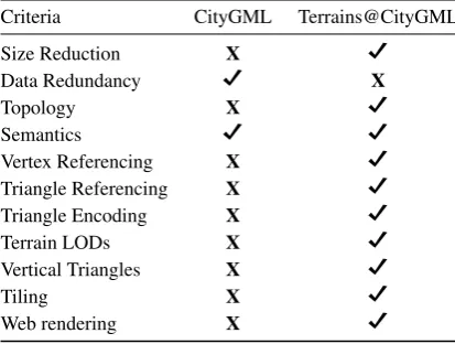
To view the structure ofTerrains@CityGMLrepresentation, a prototype is built. Currently, it permits the user to read a Geo-database file (*.GDB, the formal in which 3DTOP10NL is cur-rently available) and outputs the terrain to aTerrains@CityGML representation. The prototype reads the GDB file and removes the redundant vertex information and maps the linear ring structure of triangles to an index based referencing scheme. The results of the prototype testing are given in Table 1. The proposed extension Terrains@CityGML is expected to have the following advantages over current CityGML as shown in Table 2.
6. DISCUSSION AND FUTURE WORK
Dataset layer # features # triangles CityGML Terrains@CityGML compression factor
Tile #26CN/2 terrain 2,753 1,162,467 672.7 MB 25.2 MB 26.6
Tile #37EN/2 terrain 4,317 1,503,241 893.3 MB 34.9 MB 25.59
whole 3DTOP10NL terrain 2,465,626 1,156,641,666 686.9 GB 28.6 GB 24.01
Table 1: CityGML and Terrains@CityGML Outputs
Criteria CityGML Terrains@CityGML
Table 2: CityGML vs Terrains@CityGML
we are also working for the remaining problems as highlighed in Section 3 including the concept of LODs for terrain, handling vertical triangles, tiling CityGML datasets, integrating TINs and raster grids, etc.The LOD feature is an important characteristic of 3D city models. It enables gradual refinement of model geome-try supplemented with required semantics. Different LODs serve different applications and provide quality information of models. CityGML supports five LODs which in theory can be applied to all the urban features represented with CityGML e.g.buildings, vegetation, bridges, relief, etc. But in reality the concept is not consistent for all the available features. The CityGML LOD con-cept was primarily defined for the Building module. It describes good enough how a building can be represented in 5 different LODs starting from a footprint (LOD-0) to an architecturally rich build ing with interiors (LOD-4). But this cannot be simply ex-tended to other modules of CityGML e.g.relif, landuse, etc. The description of LODs for other modules is unclear from the per-spectives of geometry and semantics. For instance, in case of Relief module, there is no explanation regarding the simplifi-cation of a terrain for each LOD. There is no widely-accepted LOD paradigm for terrains in 3D city modelling. We propose to develop a LOD concept exclusively for terrains. At present several criteria in the field of GIS and computer grahics which can serve as a starting point for modelling terrain LODs are be-ing explored like application/context, semantics, distance, size, view focus, etc. As 3DTOP10NL is a 2.8D model with verti-cal walls and with no clear mechanism in CityGML to handle vertical walls, we plan to introduce a new class in the schema for identifying such structures. This will be helpful in performing ge-ometrically valid transformations from 3D to 2D. To alleviate the bottlenecks associated with rendering massive CityGML terrains over web, we also aim to introduce the structures of the concepts of tristrips (Speckmann and Snoeyink, 2001) and stars (Ledoux, 2015) as encoding in the CityGML/GML schema. With con-secutive ordering of vertices of triangles in the CityGML/GML instances, after the first three vertices forming the first triangle, rendering of each next triangle will only require the next ver-tex in order. Future work intends to include the other remain-ing concepts as listed in Table 3 and develop a workable zipped format forTerrains@CityGML. It would be interesting to see the processing and storage of massive datasets with complete
Terrains@CityGML.
ACKNOWLEDGEMENTS
This research is supported by the Dutch Technology Foundation STW, which is part of the Netherlands Organisation for Scientific Research (NWO), and which is partly funded by the Ministry of Economic Affairs.
References
Biljecki, F., Stoter, J., Ledoux, H., Zlatanova, S. and C¸ ¨oltekin, A., 2015. Applications of 3D City Models: State of the Art Review. ISPRS International Journal of Geo-Information 4(4), pp. 2842–2889.
Brink, L., Stoter, J. and Zlatanova, S., 2013. UML-based ap-proach to developing a CityGML Application Domain Exten-sion. Transactions in GIS 17(6), pp. 920–942.
de Laat, R. and Van Berlo, L., 2011. Integration of BIM and GIS: The development of the CityGML GeoBIM extension. In: Advances in 3D geo-information sciences, Springer, pp. 211– 225.
Dyken, C. and Floater, M. S., 2006. Preferred directions for re-solving the non-uniqueness of Delaunay triangulations. Com-putational Geometry 34(2), pp. 96–101.
Dyn, N., Levin, D. and Rippa, S., 1990. Data dependent trian-gulations for piecewise linear interpolation. IMA journal of numerical analysis 10(1), pp. 137–154.
Edelsbrunner, H. and M¨ucke, E. P., 1990. Simulation of Simplic-ity: A technique to cope with degenerate cases in geometric algorithms. ACM Transactions on Graphics 9(1), pp. 66–104.
Elberink, S. O., Stoter, J., Ledoux, H. and Commandeur, T., 2013. Generation and dissemination of a national virtual 3D city and landscape model for the Netherlands. Photogrammetric engi-neering & remote sensing 79(2), pp. 147–158.
Gr¨oger, G. and L¨owner, M.-O., 2016. Proposal for a new LoD concept for CityGML 3.0. Technical report, CityGML OGC Work Package 03.
Gr¨oger, G. and Pl¨umer, L., 2005. How to get 3-D for the price of 2-D? Topology and consistency of 3-D urban GIS. Geoinfor-matica 9(2), pp. 139–158.
Groger, G., Kolbe, T. H., Nagel, C. and H¨afele, K.-H., 2012. OGC City Geography Markup Language (CityGML) Encod-ing Standard version 2.0.0.
Isenburg, M., Liu, Y., Shewchuk, J. and Snoeyink, J., 2006. Streaming computation of delaunay triangulations. In: ACM Transactions on Graphics (TOG), Vol. 25number 3, ACM, pp. 1049–1056.
Kadaster, 2015. 3DTOP10NL. http://arcg.is/1GKYy7E. (Last accessed: April 15, 2016).
Kim, Y., Kang, H. and Lee, J., 2014. Developing CityGML In-door ADE to manage inIn-door facilities. In: Innovations in 3D Geo-information sciences, Springer, pp. 243–265.
Kumar, K., Ledoux, H. and Stoter, J., 2016. Comparative analysis of data structures for storing massive TINs in a DBMS. Inter-national Archives of the Photogrammetry, Remote Sensing and Spatial Information Sciences XLI-B2, pp. 123–130.
Kumler, M., 1994. An intensive comparison of Triangulated Ir-regular Networks (TINs) and digital elevation models (dems). Cartographica (2), pp. 1–99.
Ledoux, H., 2008. FieldGML: An alternative representation for fields. In: Headway in Spatial Data Handling, Springer, pp. 385–400.
Ledoux, H., 2015. Storing and analysing massive TINs in a DBMS with a star-based data structure. Technical Report 2015.01, 3D geoinformation, Delft University of Technology, Delft, the Netherlands.
L¨owner, M.-O., Benner, J., Gr¨oger, G. and H¨afele, K.-H., 2013. New concepts for structuring 3D city models - An extended level of detail concept for CityGML buildings. In: Compu-tational Science and Its Applications–ICCSA 2013, Springer, pp. 466–480.
Nativi, S., Caron, J., Davis, E. and Domenico, B., 2005. Design and implementation of netCDF markup language (NcML) and its GML-based extension (NcML-GML). Computers & Geo-sciences 31(9), pp. 1104–1118.
Nouvel, R., Bahu, J.-M., Kaden, R., Kaempf, J., Cipriano, P., Lauster, M. and Casper, E., 2015. Development of the CityGML Application Domain Extension Energy for urban en-ergy simulation. Proceedings of Building Simulation 2015.
OGC, 2011. OpenGISR Implementation Specification for
Ge-ographic Information-Simple feature access-Part 1: Common architecture. OGC document version 06-103r4.
OGC, 2012. OGC city geography markup language (CityGML) encoding standard. Open Geospatial Consortium inc. Docu-ment 12-019, version 2.0.0.
Okabe, A., Boots, B., Sugihara, K. and Chiu, S. N., 2009. Spatial tessellations: concepts and applications of Voronoi diagrams. Vol. 501, John Wiley & Sons.
Rippa, S., 1990. Minimal roughness property of the delaunay tri-angulation. Computer Aided Geometric Design 7(6), pp. 489– 497.
Sen, M. and Duffy, T., 2005. GeoSciML: Development of a generic geoscience markup language. Computers & Geo-sciences 31(9), pp. 1095–1103.
Shewchuk, J. R., 1996. Triangle: Engineering a 2D Quality Mesh Generator and Delaunay Triangulator. Applied Computational Geometry: Towards Geometric Engineering 1148, pp. 203– 222.
Shewchuk, J. R., 1997. Delaunay Refinement Mesh Generation. PhD thesis, School of Computer Science, Carnegie Mellon University, Pittsburg, USA.
Speckmann, B. and Snoeyink, J., 2001. Easy triangle strips for TIN terrain models. International journal of geographical in-formation science 15(4), pp. 379–386.
Stadler, A. and Kolbe, T. H., 2007. Spatio-semantic coherence in the integration of 3D city models. In: Proceedings of the 5th International Symposium on Spatial Data Quality, Enschede.
van den Brink, L., Stoter, J. and Zlatanova, S., 2013. Establish-ing a national standard for 3D topographic data compliant to CityGML. International Journal of Geographical Information Science 27(1), pp. 92–113.
VTP, 2012. ITF Format - Virtual Terrain Project. http:
//vterrain.org/Implementation/Formats/ITF.html.
(Last accessed: July 25, 2016).