Springer Series in
Springer Series in
materials science
Editors: R. Hull R. M. Osgood, Jr. J. Parisi H. Warlimont
The Springer Series in Materials Science covers the complete spectrum of materials physics, including fundamental principles, physical properties, materials theory and design. Recognizing the increasing importance of materials science in future device technologies,the book titles in this series reflect the state-of-the-art in understanding and controlling the structure and properties of all important classes of materials.
99 Self-Organized Morphology in Nanostructured Materials Editors: K. Al-Shamery, S.C. Müller, and J. Parisi
100 Self Healing Materials An Alternative Approach
to 20 Centuries of Materials Science Editor: S. van der Zwaag
101 New Organic Nanostructures for Next Generation Devices Editors: K. Al-Shamery, H.-G. Rubahn, and H. Sitter
102 Photonic Crystal Fibers Properties and Applications By F. Poli, A. Cucinotta, and S. Selleri
103 Polarons in Advanced Materials Editor: A.S. Alexandrov
104 Transparent Conductive Zinc Oxide Basics and Applications
in Thin Film Solar Cells Editors: K. Ellmer, A. Klein, and B. Rech
105 Dilute III-V Nitride Semiconductors and Material Systems
Physics and Technology Editor: A. Erol
106 Into The Nano Era
Moore’s Law Beyond Planar Silicon CMOS Editor: H.R. Huff
107 Organic Semiconductors in Sensor Applications
Editors: D.A. Bernards, R.M. Ownes, and G.G. Malliaras
108 Evolution of Thin-FilmMorphology Modeling and Simulations By M. Pelliccione and T.-M. Lu
109 Reactive Sputter Deposition Editors: D. Depla and S. Mahieu
110 The Physics of Organic Superconductors and Conductors
Editor: A. Lebed
111 Molecular Catalysts for Energy Conversion
Editors: T. Okada and M. Kaneko
112 Atomistic and Continuum Modeling of Nanocrystalline Materials Deformation Mechanisms and Scale Transition
By M. Cherkaoui and L. Capolungo
113 Crystallography and the World of Symmetry
By S.K. Chatterjee
Sanat K. Chatterjee
Crystallography
and the World
of Symmetry
With 104 Figures
Professor Sanat K. Chatterjee
National Institute of Technology, Physics Department, Mahatma Gandhi Avenue, Durgapur-713209, West Bengal, India E-mail: sanat [email protected]
Series Editors:
Professor Robert Hull
University of Virginia
Dept. of Materials Science and Engineering Thornton Hall
Charlottesville, VA 22903-2442, USA
Professor R. M. Osgood, Jr.
Microelectronics Science Laboratory Department of Electrical Engineering Columbia University
Seeley W. Mudd Building New York, NY 10027, USA
Professor Jürgen Parisi
Springer Series in Materials Science ISSN 0933-033x
ISBN 978-3-540-69898-2 e-ISBN 978-3-540-69899-9
Library of Congress Control Number: 2008930151
© Springer-Verlag Berlin Heidelberg 2008
This work is subject to copyright.All rights are reserved,whether the whole or part of the material is concerned, specifically the rights of translation, reprinting, reuse of illustrations, recitation, broadcasting, reproduction on microfilm or in any other way, and storage in data banks. Duplication of this publication or parts thereof is permitted only under the provisions of the German Copyright Law of September 9, 1965, in its current version, and permission for use must always be obtained from Springer-Verlag. Violations are liable to prosecution under the German Copyright Law.
The use of general descriptive names, registered names, trademarks, etc. in this publication does not imply, even in the absence of a specific statement, that such names are exempt from the relevant protective laws and regulations and therefore free for general use.
Typesetting: Data prepared by SPi using a Springer TEX macro package Cover concept: eStudio Calamar Steinen
Cover production:WMX DesignGmbH, Heidelberg
SPIN: 12252381 57/856/SPi Printed on acid-free paper
Preface
From the time unknown, we are appreciating the symmetry present in nature. Starting from the beautiful wings of the butterfly and the colourful flowers the world of symmetry includes the glittering gem stones. People developed the methods of gems cutting and polishing and irrespective of the sex; gems had taken their place in ornaments.
Every man being vertebrate walks similarly on foot and so a symmetry or in variance exists in the mode of their walking, but there still exists something distinctive and characteristic in every man even in walking so that we can easily recognize in dark a known individual by observing simply his style of walking. There lies the asymmetry or a deviation from total invariance. The art of finding the wonderful symmetries that exists in nature is amazing and also the finding of asymmetry so intrinsically associated with it is probably more amazing.
The book has a beginning from the concept of crystal pattern, the lattice, different crystal lattices and the Space groups (Chaps. 1–8). A rather brief passage through this concept is made by discussing the different methods for the determination of the structure of crystals.
VIII Preface
Imperfect crystals are close to the asymmetric stage of matter but being variant in the characteristics of symmetrical state, they demonstrate some important properties that an ideally perfect symmetrical state fail to give. Therefore, attention is then shifted from single crystal state to polycrystalline state and some of their characteristic properties.
The concepts and characteristics of semi-crystalline states like liquid crys-tals, quasi crystals and finally the nano crystalline states are discussed in Chap. 10. While discussing the relevant aspects of this asymmetrical state of matter due attention has been given to discuss the properties and particularly the peculiarities of their structure dependant properties which are only possi-ble to exist because of their deviation from perfect geometrically symmetrical arrangements of the constituents. The entire development is correlated with the symmetries and also the asymmetries present in matter and the laws that explain their characteristics.
Though the outline of this book is designed to serve those having only the basic introduction to mathematics, a brief introduction to the diffraction theory of perfect periodic to aperiodic structures is given in Appendix A. Some solved problems are also given in Appendix B to help students.
I express my thankfulness to Dr. M.K. Mandal for his help in proof reading. I express my gratefulness to Prof. L.S. Dent Glasser, Department of Chemistry, U. Aberdeen (Rtd) for allowing to reproduce some of the diagrams from her book “Crystallography and its applications.” I also thank my students whose interest in the subject and interactions within and outside the class room gave me the idea to undertake this venture. If the content and presentation of this book satisfy their inquisitiveness, I would consider this venture as successful.
Durgapur, India Sanat Kumar Chatterjee
Contents
1 Pattern. . . 1
1.1 Pattern: An Introduction . . . 1
1.2 Summary . . . 7
References . . . 7
2 Lattices. . . 9
2.1 Plane Lattice . . . 9
2.2 Space Lattice . . . 12
2.3 Lattice Planes and Miller Indices . . . 12
2.4 Lattice Directions . . . 13
2.5 Summary . . . 14
References . . . 14
3 Symmetry in Lattices. . . 15
3.1 Symmetry Operations in Plane Lattices . . . 15
3.1.1 Rotational Symmetry . . . 15
3.1.2 Mirror Plane of Symmetry . . . 16
3.1.3 Centre of Symmetry . . . 19
3.2 Symmetry Operation in Space Lattices . . . 19
3.2.1 Rotation Inversion (Rotary Inversion) Symmetry . . . 19
3.3 Summary . . . 21
References . . . 21
4 Crystal Symmetry (Crystal Pattern): I . . . 23
4.1 Macroscopic Symmetry Elements . . . 23
4.2 Thirty-Two Point Groups of Symmetries in Hermann–Mauguin Notations . . . 24
4.3 Crystal Systems . . . 27
4.4 Bravais Lattices . . . 28
4.5 Summary . . . 33
X Contents
5 Crystal Symmetry (Crystal Pattern): II . . . 35
5.1 Microscopic Symmetry Elements in Crystals . . . 35
5.2 Space Groups . . . 40
5.3 Constitution of Space Groups . . . 42
5.4 Summary . . . 42
References . . . 42
6 Crystals and X-Ray. . . 43
6.1 Production and Properties of X-Ray . . . 43
6.2 Laue Equations . . . 45
6.3 Bragg’s Law . . . 47
6.4 Reciprocal Lattice . . . 47
6.5 Geometry of X-Ray Diffraction: Use of Reciprocal Lattice . . . . 50
6.6 The Interplanar Distance (d-Spacing) of Different Crystal Systems . . . 53
6.7 Weighted Reciprocal Lattice . . . 55
6.8 Summary . . . 56
References . . . 56
7 Experimental Methods for Structure Analysis: X-Ray Diffraction Techniques. . . 57
7.1 Experimental Techniques for Single Crystal . . . 57
7.1.1 Laue Camera and Laue Pattern . . . 57
7.1.2 Rotation/Oscillation Camera and the Applications . . . . 60
7.1.3 Weissenberg Camera and Moving Film Technique . . . 64
7.1.4 de Jong–Boumann and Precession Camera . . . 68
7.2 Experimental Techniques for Polycrystals . . . 70
7.3 Debye–Scherrer Cylindrical Powder Camera: The Plan View . . . 72
7.4 Indexing of the Debye–Scherrer Pattern . . . 73
7.4.1 Cubic Systems . . . 73
7.4.2 Tetragonal System . . . 73
7.4.3 Hexagonal System . . . 74
7.4.4 Orthorhombic System . . . 74
7.4.5 Monoclinic and Triclinic Systems . . . 75
7.5 Summary . . . 75
References . . . 75
8 Determination of Space Group and Crystal Structure. . . 77
8.1 Determination of Space Group from Data Obtained from Moving Film . . . 77
8.1.1 Weissenberg Photographs . . . 77
8.2 Determination of Crystal Structure . . . 79
Contents XI
8.2.2 The Electron Density Equation
and Patterson Function . . . 80
8.3 Summary . . . 83
References . . . 84
9 The World of Symmetry. . . 85
9.1 Symmetry in Living Bodies . . . 86
9.2 Symmetry in Patterns, Snow Flakes, and Gems . . . 89
9.3 Symmetry in Architecture . . . 91
9.4 Symmetry in Fundamental Particles . . . 91
9.5 Symmetry (Invariance) of Physical Laws . . . 95
9.6 Summary . . . 98
References . . . 99
10 Asymmetry in Otherwise Symmetrical Matter. . . 101
10.1 Single Crystals, Poly Crystals, and Asymmetry–Symmetry . . . . 101
10.2 A Symmetry in Asymmetry I: Quasi Crystalline State of Matter . . . 106
10.3 A Symmetry in Asymmetry II: Liquid Crystalline Phase . . . 111
10.3.1 Optical Study of Liquid Crystals . . . 114
10.3.2 Effect of Electric Field on Nematic Liquid Crystal (Electro-Optical Effect) . . . 116
10.4 Symmetry Down to the Bottom: The Nanostructures . . . 116
10.5 Summary . . . 126
References . . . 126
Epilogue. . . 127
A An Outline of the Diffraction Theory of Periodic and Aperiodic Structures. . . 129
References . . . 135
B Solved Problems. . . 137
Further Reading. . . 145
1
Pattern
1.1 Pattern: An Introduction
2 1 Pattern
♣
♣
♣
♣
♣
♣
♣
♣
♣
♣
♣
♣
♣
♣
♣
♣
♣
♣
♣
♣
Fig. 1.1.Same motif, a perfect pattern
♥
•
∗
♠
♦
♦
♠
♠
∗
♥
♠
∗
♦
•
∗
♠
∗
♠
∗
♥
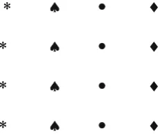
Fig. 1.2.Regular arrangement of random motifs, not a pattern
∗∗
♠
•
♦
∗
♠
•
♦
∗
♠
•
♦
∗
♠
•
♦
Fig. 1.3. The motifs are different but they bear a constant regularity in their arrangement, and so it constitute a pattern
printed cloths must also satisfy an order of their arrangement both in their translation or position and after orientation [1].
In Figs. 1.1 and 1.2, two arrangements of motifs are created such that in one all the motifs are similar and in the other, they are different. Now the question is, which one of these two appears more soothing to our eye? There lies perhaps the subjectivity of the problem. But if we do not only restrict ourselves to the more common geometric senses, then also the first one (Fig. 1.1) appears definitely more soothing to the eye and so can be accepted as a pattern and whereas the latter is not at least as in Fig. 1.1.
1.1 Pattern: An Introduction 3
Note: The scheme of repetition or the mode of arrangement of motifs is the same in all figures. The only difference is that in Fig. 1.1 the motifs are similar and in Figs. 1.2 and 1.3 they are different. The pattern in Fig. 1.1 is more regular than that in Fig. 1.2 and also in Fig. 1.3, but Fig. 1.3 is more “pattern-like” than Fig. 1.2.
Conclusion: To constitute a pattern, the motifs are either to be same or should be regularly arranged in the same scheme of repetition even if they are dif-ferent. The scheme of repetition comprises of position and orientation of the motifs.
Now, if the motifs are identical but the mode of their arrangement, that is, the scheme of their repetition is changed then the pattern will also be changed. This is shown in Figs. 1.4 and 1.5.
Note: In both Figs. 1.4 and 1.5, the patterns are created but they look differ-ent because their schemes of repetition are differdiffer-ent. Again in Fig. 1.6 though there is regularity in arrangement, it looks less pattern-like than Fig. 1.7 as the color of the motifs is random in Fig. 1.6, whereas the motifs are system-atically colored in Fig. 1.7 and so it appears more pattern-like. In Fig. 1.8 each motif are similar but randomly oriented but positioned in regular order, and in Fig. 1.9 both are maintained and so it is a regular geometric pattern. Figure 1.10 shows another pattern though motifs are oriented but in sym-metrical right-hand screw order. This can be understood in more elaborate
♣
♣
♣
♣
♣
♣
♣
♣
♣
♣
♣
♣
♣
♣
♣
♣
♣
♣
♣
♣
♣
Fig. 1.4.A pattern with one scheme of repetition
♣
♣
♣
♣
♣
♣
♣
♣
♣
♣
♣
♣
♣
♣
♣
♣
♣
♣
♣
♣
♣
♣
♣
♣
♣
♣
♣
♣
♣
♣
♣
♣
♣
4 1 Pattern
♣
♣
♣
♣
♣
♣
♣
♣
♣
♣
♣
♣
♣
♣
♣
♣
♣
♣
♣
♣
♣
Fig. 1.6.Regular arrangement of randomly coloured motifs
♣
♣
♣
♣
♣
♣
♣
♣
♣
♣
♣
♣
♣
♣
♣
♣
♣
♣
♣
♣
♣
♣
♣
♣
♣
♣
♣
♣
♣
♣
♣
♣
♣
Fig. 1.7. Regular arrangement of symmetrically coloured motifs
▲
►
▼
◄
►
◄
▼
◄
◄
►
▼
◄
►
◄
►
◄
▼
◄
►
►
Fig. 1.8.Same motifs, symmetrically placed but randomly oriented
◄
◄
◄
◄
◄
◄
◄
◄
◄
◄
◄
◄
◄
◄
◄
◄
◄
◄
◄
◄
1.1 Pattern: An Introduction 5
►
◄
◄
►
◄
►
►
◄
►
◄
◄
►
◄
►
►
◄
Fig. 1.10.Motifs symmetrically placed and also oriented
Fig. 1.11. Motifs are triangles and each is placed in perfect symmetrical position to constitute a pattern
Fig. 1.12. Motifs are triangles and are same as Fig. 1.11 and they are placed in perfect symmetrical positions but are randomly oriented about their positions and so it loses the characteristics of the pattern
way from Figs. 1.11 and 1.12, where in the motifs are triangles and they are differently placed so far as their orientation is concerned but in symmetrical positions.
6 1 Pattern
Therefore, a pattern must possess two characteristics, the regular motifs stationed at sites that obey a certain scheme of repetition [1, 2]. Any change of motif or the change of the repetition scheme both in their positions and orientation changes the pattern. So to study a pattern these two aspects are to be looked into and studied. It is more convenient to start with the study of different possible schemes of repetition that exist in their position rather than with the orientation symmetry, if there is any, in the motifs. The former class of study may be categorized as Macroscopic whereas the latter may be called as Microscopic. To begin with the investigation on scheme of repetition, it should be appreciated that the regularity of the scheme of repetition including both macro and micro is the essence of a perfect pattern [3]. This regularity generates a sense of symmetry, which is later described as Macroscopic and Microscopic. It is better to start with the symmetry present in the scheme of repetition, that is, with the symmetry operations.
Note: Two bodies or configuration of bodies (i.e., Pattern) may be called symmetrical if and only if they are indistinguishable in all respect. The sym-metry operations are those operations which when performed on a pattern, the pattern returns back to its state of self-coincidence or invariance.
Thus the total identification of the symmetry operations that can be per-formed to bring a pattern in to its self coincidence, gives the knowledge of the symmetry and the scheme of repetition present in the pattern.
This should be appreciated that the entire knowledge of symmetry or scheme of repetition present in the pattern though include the sense of motifs present, it would be much beneficial at least to start with if we consider the symmetry present within the sites of the motifs only (Macroscopic), and when these are known, then the symmetry operations including the motifs (Microscopic) can be considered. Therefore, let us start with the symmetry present within the sites where the motifs are to be placed to generate the patterns.
These sites of the motifs, which are represented by simple geometrical points, have a special significance and they are known as “Lattice.”
References 7
1.2 Summary
1. A pattern has two constituents: one is themotifand the other isthe scheme of repetitionof the motif.
2. The scheme of repetition of motifs again has two aspects: Positions in the lattice sites (macroscopic) and the orientation (microscopic) in their respective lattice sites.
3. A pattern has two aspects: one is the structure of the motif and its schemes of repetition and the other is its pleasant visual effect. This is the after effect when these two aspects are followed. Therefore, both these two aspects, that is, the symmetry and the visual effect are important and are usually supplementary to each other.
4. When the first aspect is not at all or is only partially followed, it is not necessary that the assembly of the motifs will not satisfy the second aspect of it, that is, the visual pleasure and will fail to constitute a pattern. It is then an incidence of an exception in the geometric rule of pattern, that is, asymmetry in symmetry, which is abundantly present in nature.
References
1. N.F. Kenon,Patterns in Crystals(Wiley, New York, 1978)
2. L.S. Dent Glasser,Crystallography and its Applications(Van Nostrand Reinhold Co. Ltd, New York, 1977)
2
Lattices
2.1 Plane Lattice
The two-dimensional infinite array of geometrical points symmetrically arranged in a plane where the different motifs may be placed to create the patterns is known as plane lattice. Figures 2.1 and 2.2 are the examples of plane lattices, where the neighborhood of every point is identical. Figures 2.1 and 2.2 are two types of plane lattices, where motifs are to be placed to generate the desired patterns [1].
Note: The plane lattice of a two-dimensional pattern is that array of geometric points which specifies the scheme of repetition that is present in the pattern. There is no difference between the neighbors of one lattice site from any of its neighborhood. Actually the situation becomes so much identical that if the attention from one lattice point is removed, it then becomes impossible to identify and locate the same lattice point.
Note: The unit translation is the distance shown by arrow between adjacent points along any line in a lattice. This distance taken between any adjacent point isa, anddis the distance of separation between any line drawn through the points in the lattice (Figs. 2.3 and 2.4).
The product ofaandd, that is,a×dis the total area associated with each lattice point and the inverse, that is, 1/(a×d) is the number of points in each unit area of the lattice. The unit cell of the plane lattice is a parallelogram of two unit translations with lattice points at the corners and is the representa-tive of the lattice, that is, the lattice is constituted by repeating this unit cell in two directions of the plane lattice.
This unit cell is completely specified by the lengths of the edges known as unit translations and the angle between them. So, the unit cell is the building block of the lattice (Fig. 2.5) [1–3].
10 2 Lattices
•
•
•
•
•
•
•
•
•
•
•
•
•
•
•
•
•
•
•
•
Fig. 2.1.Plane Lattice (Type I)
•
•
•
•
•
•
•
•
•
•
•
•
•
•
•
•
•
•
•
•
•
•
•
•
•
•
•
•
•
•
•
•
Fig. 2.2.Plane Lattice (Type II)
•
•
•
•
•
•
•
•
d•
•
•
•
•
•
•
a
•
•
•
•
•
Fig. 2.3.Distances between lattice sites and lattice rows (Type I)
•
•
•
•
•
•
•
•
•
•
•
•
•
•
•
•
•
a•
•
•
•
•
•
•
•
•
•
•
•
•
•
•
2.1 Plane Lattice 11
Fig. 2.5. A unit cell, ABCD the building block of the lattice. Two sides are of lengthsaandbandαis the angle between them
. . . .
Fig. 2.6. Plane lattice structure. There are possibilities of different shapes of unit cells, each having different sets of a and band also the angles between them, but each one preserve one condition: they are formed by joining only the corner sites
unlimited values of aandb, but the actual fact is that the pattern types are dependent not on the value of a and b but whether a = b or a = b and whether α = 90◦
or α = 90◦
but equal to 120◦
. These different conditions can only lead to different types of plane lattices. Based on this observation it can be concluded that there are five different types of plane lattices out of six possible unit cells as a pentagon cannot act as a building block for a continuous two-dimensional pattern [2, 3].
(1) Square [a=band α= 90◦
This unit cell is not considered as a building block.
12 2 Lattices
Square Rectangle
Parallelogram Pentagon*
Rhombus Hexagon
Fig. 2.7.Different possible shapes of unit cells of plane lattices
The question may arise why a pentagonal unit cell is not generally possi-ble? The answer to this interesting question may be obtained from the con-sideration of two aspects of the pattern. The one is the unit cell concon-sideration and the other from the symmetry consideration, which will be discussed later. From the first consideration, it can be said that as the unit cells are building block of the pattern, by repeating the pentagon in a plane it is not possible to construct a plane lattice. This aspect as mentioned will be taken up in a later chapter.
2.2 Space Lattice
If we add one more dimension to the plane lattice and arrange the geometrical points also in the third axis obeying the order, then it constitutes a space lattice. The unit cell of the space lattice is the three-dimensional building block of the space lattice, which when are arranged in three directions obeying the order of repletion will constitute the space lattice. The three axial lengths and the angles between them then are required to specify the unit cell. Figure 2.8 shows the unit cell of a space lattice.
2.3 Lattice Planes and Miller Indices
Unlike plane lattice where the lines joining lattice points are lines, here in space lattice it generates a plane known as lattice plane. As it is important to know these lattice planes and as they preserve their individuality in much respect, each such lattice planes are identified by indices known as Miller indices,hkl. These indices are given to a plane by the following procedures [3, 4]:
2.4 Lattice Directions 13
c
0 a
b
Fig. 2.8. a, b, andcare unit translations andα, β, andγ are the angles between bandc, aandc, andaandb, respectively
(a) Intercepts : a, ∝ and ∝ (b) 1, ∝/b and ∝/c (c) 1, b/∝ and c/∝ (d) 1, 0, 0 (e) (100) (a) a, b and ∝
(b) 1, 1 and ∝/c (c) 1, 1 and c/∝ (d) 1, 1 and 0 (e) (110)
(b) 1, 1, 1 (c) 1, 1, 1 (d) 1, 1, 1 (e) (111) b
c
a
(a) Intercepts : a, b and c
Fig. 2.9.The Miller indices of some planes
(c) Invert the dividends
(d) Rationalize the inverted dividends
(e) Place the rationalized numbers in round brackets
Figures 2.9 and 2.10 explain the procedures as mentioned above.
The sets of planes (hkl) are noted by {hkl}. The {110} family of planes comprises six planes, that is, (110), (101), (011), (¯¯1¯10), (¯10¯1), and (0¯1¯1). The bars as usually signify the intercept in the negative side of the axes. All these planes belong to the same class and together they are represented by{110}.
2.4 Lattice Directions
Like the indices of a lattice plane, the lattice directions are also important aspects to be known. They are also noted by Miller indices and are done as follows:
14 2 Lattices
c
a b _ 111 _
111
111
_ _ 111
_ _ 111
Fig. 2.10.Miller Indices of some more planes with axes showing separately
(b) Divide the coordinates of the point by appropriate unit translations (c) Rationalize the dividends
(d) Place the rationalized dividends in a square bracket
Note: [uvw] refer to any direction in a space lattice. [¯111] and [1¯1¯1] are opposite senses of the same line [3, 4].
In space lattices in addition to the unit translational distances called vec-tors like a, b, and c and angles as α, β, and γ between them the distances between different lattice planes designated by their respective Miller indices are also important. These distances are known as interplaner distances and are designated by ‘d’ spacings. The derivation of their expressions is done in a later chapter after the introduction of crystal classes.
2.5 Summary
1. A lattice is an array of geometrical points either in two or in three dimen-sions to make plane or space lattices.
2. This array of points shows the order in the scheme of repetition.
3. This scheme of repetition is maintained although the lattice, that is, every region of a lattice is exactly identical with other.
4. The different planes and also the directions on which these lattice points lie are designated by indices known as Miller indices.
References
1. N.F. Kenon,Pattern in Crystals(Wiley, New York, 1978)
2. L.V. Azaroff,Elements of Crystallography(Mc Graw Hill, New York, 1968) 3. C.S. Barrett, T.B. Massalski,Structure of Metals(Mc Graw Hill, New York, 1956) 4. M.J. Buerger, Elementary Crystallography, an Introduction to the Fundamental
3
Symmetry in Lattices
In discussing the unit cells of five different kinds in plane lattices, it has been understood that more a unit cell is complex, greater is the number of parameters required to specify that cell. This complexity of the unit cells is determined by the “symmetry properties” of the array of points in the different types of plane and space lattices.
The symmetry properties of a lattice are specified by one or more than one operation, which when are executed over a lattice point, the entire lattice can be constructed. Each point of the lattice is brought back to another identical point. It should be taken in mind that when we discuss only with lattices, the symmetry exists only due to the scheme of repetition, but when the motifs are placed the symmetry changes, but the symmetry in the lattice is the minimum symmetry present.
3.1 Symmetry Operations in Plane Lattices
3.1.1 Rotational Symmetry
In Fig. 3.1, ABCD is a parallelogram. If the diagram is rotated alongX-Y
axis clockwise or anticlockwise through angles 180◦
or 360◦
, then the diagram returns to its self coincidence. The minimum angle through which it can be rotated to bring it into self coincidence is 180◦
. If instead of a parallelogram or rectangle the diagram was a square, then the minimum angle through which it had to be rotated for self coincidence would be 90◦
.
16 3 Symmetry in Lattices
(1) Rotational symmetry:
X
D
A B
Y
C
Fig. 3.1. Rotation axis of symmetry
Note: A nfold rotation axis of symmetry is a line about which the body or the pattern is transformed to self coincidencentimes during a 360◦
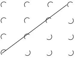
rotation. The rotation axes of symmetry from onefold to sixfold rotation are shown in Fig. 3.2a–f and the details of rotation angles to bring the lattice into self-coincidence are also given in Table 3.1. It is evident from the above figures that onefold of rotation is present in any irregular shaped body; the fivefold rotation axis of symmetry is not possible in regular pattern as its unit cell, which is a regular pentagon, cannot be arranged even in a plane so as to make any plane pattern. There is some exception to this, that is, possibility of fivefold symmetry (Fig. 3.3). This aspect will be taken up in a later Chapter. Sevenfold or more than that will either fail to make a regular unit cell or they will be repetition of any of the one- to sixfold of rotations [1–3].
Note: The highest rotational symmetry that occurs in the plane lattice is the rotational symmetry of the plane lattice and fivefold of rotation is not possible. However, there are some exceptions to this in quasi crystalline state of matter, which will be discussed in a later chapter.
3.1.2 Mirror Plane of Symmetry
3.1 Symmetry Operations in Plane Lattices 17
X
X X
•• • •
(a) (b) (c) X/ X/
X
(f ) X/
X/
X X
(e*) (d)
X/ X
/
(h) (g)
18 3 Symmetry in Lattices
Table 3.1. Different rotational symmetries present in plane or space lattices Sl. No. θ, the rotation 360◦/θ Symmetry Numerical symbol
angle axis (Hermann–Mauguin)
1 360◦ 1 Onefold 1
2 180◦ 2 Twofold 2
3 120◦ 3 Threefold 3
4 90◦ 4 Fourfold 4
5 72◦ 5 Fivefold 5∗
6 60◦ 6 Sixfold 6
Fig. 3.3. It shows the impossibility of fitting regular pentagons having fivefold of rotation symmetry in condensed matter structure. Any such attempt will leave either voids or an overlap of the pentagons [2]
· · · · ·
· · · · ·
· · · Horizontal
· · · Diagonal
Diagonal Vertical
Fig. 3.4.Four mirror planes in a plane lattice
3.2 Symmetry Operation in Space Lattices 19
j
j
j
j
j
j
j
k
j
j
k
k
j
k
k
k
Fig. 3.5.One diagonal mirror plane in the pattern
f
d c
b
a
g P
e
Fig. 3.6.An irregular polygon has a centre of symmetry at the point P. Each point is equidistant from P, from the corresponding point on the opposite side of centre point P. If every point within a body can be inverted through a centre then the body is transformed to self coincidence by the inversion
3.1.3 Centre of Symmetry
A body has a centre of symmetry (Symbol ¯1) if for every point in it there is an identical point equidistant from the centre but on opposite side in the inverted state (Fig. 3.6).
Note: The unit cells of all plane lattices have a centre of symmetry, but whether the unit cell of a pattern has a centre of symmetry depends on the shape of the motif.
3.2 Symmetry Operation in Space Lattices
3.2.1 Rotation Inversion (Rotary Inversion) Symmetry
20 3 Symmetry in Lattices
inversion symmetry or simply roto-inversion. This symmetry operation is the combined effect of pure rotation and inversion of the lattice point to bring it into self-coincidence.
They are the following:
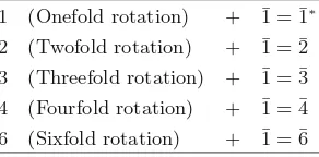
1 (Onefold rotation) + ¯1 = ¯1∗
2 (Twofold rotation) + ¯1 = ¯2 3 (Threefold rotation) + ¯1 = ¯3 4 (Fourfold rotation) + ¯1 = ¯4 6 (Sixfold rotation) + ¯1 = ¯6
Figure 3.7 demonstrates this rotation inversion symmetry operation in space lattices.
Note: The onefold roto-inversion (¯1) and twofold roto-inversion (¯2) may exist on a plane but higher roto-inversion symmetries must move out of the plane and so this symmetry is called a symmetry operation in space lattices.
Conclusion: The symmetry elements that may occur without any repetition in space lattices are as follows:
Rotation Axes: 1, 2, 3, 4, and 6
Centre of Symmetry: 1
Rotation Inversion Axes: 3, 4, and 6
Mirror plane:m(2)
Note: As ¯1, that is, onefold rotation and inversion is same as centre of symme-try and ¯2, that is, twofold rotations and inversion is also same as the mirror plane, they are not included as separate symmetry elements in space lattices.
A⬘0
• A
C• _
1
•
• B
Fig. 3.7.Fourfold rotation inversion. A is given 90◦rotation about the rotation axis
X-Y.Filled circlechanges toopen circle(A to A′) then inversion about the centre
References 21
a
⬘a
⇑
⇑
B
C
D
⇓
a
⬘⬘Fig. 3.8. Equivalence of ¯2 and m a to a′ by a twofold rotation and then inversion
to a′′. These entire operations are equivalent to a simple mirror reflection over the
plane ABCD (a changes directly to a′′)
Example: Figure 3.8 shows that a twofold rotation inversion is same as mirror plane. The motif⇑at position a has undergone a twofold rotation to position a′
and then subsequently by inversion to position a′′
, which can also be obtained by a simple mirror reflection over the plane ABCD [3].
3.3 Summary
1. Lattice, which is the array of points, the sites of the motifs, gives the knowledge of the particular scheme of repetition present.
2. The scheme of repetition is controlled by “symmetry operations,” which when performed the lattice goes to an identical situation of existence, that is, the position of self coincidence or the position of invariance.
3. The scheme of repetition may or may not alter after the motifs are placed at the lattice sites as then the symmetry will also depend on the structure and nature of the motifs.
References
1. F.C. Philips, An Introduction to Crystallography (Oliver and Boyd, Edinburgh, 1971)
2. L.S. Dent Glasser,Crystallography and Its Applications(Van Nostrand Reinhold Co., New York, 1977)
4
Crystal Symmetry (Crystal Pattern): I
4.1 Macroscopic Symmetry Elements
We have already introduced the space lattice and the symmetry elements that are possible in the space lattices. It has also been mentioned that when a pattern is constituted by placing the motifs in the lattice sites, these symmetry elements originally present in the space lattice of the pattern may be reduced due to the shape of the motifs; however, this is not true only when the motifs are isotropic in their shape. If the motifs are atoms or molecules then the pattern itself is a crystal. Therefore, the crystals can be regarded as three-dimensional patterns. When some of the symmetry elements present in the corresponding space lattices are also present in the crystal, they are named as macroscopic symmetry elements as they are manifested by the regular external faces of the crystals and as most of them can be studied by unaided eye by observing the single crystal faces. These macroscopic symmetry elements present in a crystal can be once again recalled as in Table 4.1.
The total macroscopic symmetry of a crystal or a pattern is then that col-lection of symmetry elements which is associated with the point at the centre of the crystal. Now, since every point of a space lattice is indistinguishable from every other point, the collection of elements defining the symmetry of the lattice must be associated with each and every point of the lattice. Thus, to completely specify the macroscopic symmetry of the lattice it is necessary only to specify the symmetry at any point in that lattice.
The collection of symmetry elements at any point of the lattice is termed as thepoint symmetryor thepoint group of symmetry.
24 4 Crystal Symmetry (Crystal Pattern): I
Table 4.1.Symmetry Operations and Symbols
Sl. no. Symmetry operation Symmetry elements Total Hermann–Mauguin symbol
1 Mirror plane mor ¯2 1
2 Centre of symmetry ¯1 1
3 Rotation axis 1, 2, 3, 4, 6 5
4 Rotary inversion ¯3,¯4,¯6 3
Total number of macroscopic symmetry elements = 10
Cube = 3-fold rotation (4 in No) = 4-fold rotation (3 in No.) = 2-fold rotation (6 in No.)
Side face diagonal Body diagonal Side edge Face diagonal plane
Fig. 4.1. Different planes and rotation axes in cube. ∆ = threefold rotation (4 in number);= fourfold rotation (3 in numbers);= twofold rotation (6 in numbers)
A detailed analysis of the compatibility of the ten symmetry elements in all possible combinations is beyond the scope of this book. It can be analyzed that out of a large number of possible groupings of these ten symmetry elements, only 32 are compatible combinations of one or more of them and thus there exist only 32point groupsof symmetry (Fig. 4.1).
4.2 Thirty-Two Point Groups of Symmetries
in Hermann–Mauguin Notations
1 1 A onefold rotation axis (no symmetry at all)
2 ¯1 A centre of symmetry only
3 2 A twofold rotation axis only
4 m(¯2) A single mirror plane
4.2 Thirty-Two Point Groups of Symmetries in Hermann–Mauguin Notations 25
6 222 Three twofold rotation axes at right angles to one another
7 2mm Two mirror planes at right angles to one an-other with a twofold rotation axis along the line of intersection of the mirror planes 8 2/m2/m2/m Three mirror planes at right angles to one
another with a twofold rotation axis along each of the three lines of intersection 9 3 A threefold rotation axis only 10 ¯3 A threefold rotary inversion axis
11 3m Three mirror planes at 120◦ to one another
intersecting along a threefold rotation axis 12 32 A threefold rotation axis passing at right
an-gles through the intersection of three twofold axes at 120◦ to each other
13 ¯3 2/m Three mirror planes at 120◦ to each other
intersecting along a threefold rotary inver-sion with three twofold axes at right angles to the rotary inversion and midway between the mirror planes
14 4 A fourfold rotation axis only 15 ¯4 A fourfold rotary invertor only
16 4/m A fourfold rotation axis with a mirror plane at right angle to it
17 4 2 2 A fourfold rotation axis passing at right an-gles through the intersection of four twofold rotation axes at 45◦to one another
18 4mm Four mirror planes at 45◦to one another with
a fourfold rotation axis along the line of in-tersection
19 4/m2/m2/m Four mirror planes at 45◦to one another
in-tersecting along a fourfold rotation axis; an additional mirror plane at right angles to the fourfold axis intersects the other mirror planes along four twofold rotation axes 20 ¯4 2m Two mirror planes intersecting along a
four-fold rotary invertor with two twofour-fold rotation axes at right angles to the rotary inversion and midway between the mirror planes
21 6 A sixfold rotation axis
22 ¯6 A sixfold rotary inversion
23 6/m A sixfold rotation axis with a mirror plane at right angle to it
24 6mm Six mirror planes at 30◦ to one another
in-tersecting along a sixfold rotation axis 25 6 2 2 A sixfold rotation axis passing at right
26 4 Crystal Symmetry (Crystal Pattern): I
26 ¯6 2m Three mirror planes at 60◦ to each other
intersecting along a sixfold rotary inver-sion, each mirror plane containing a twofold rotation axis at right angles to the rotary in-version axis
27 6/m2/m2/m Six mirror planes at 30◦ to each other
in-tersecting along a sixfold rotation axis, each mirror plane containing a twofold rotation axis at right angles to the sixfold axis and lying in a mirror plane also at right angles to the sixfold axis
28 23 Three twofold axes at right angles to one an-other and parallel to the edges of a cube with four threefold axes parallel to the body diag-onals, i.e., four threefold axes at 70◦32/to one
another
29 2m¯3 Three mirror planes parallel to the face of the cube, intersecting along three twofold axes parallel to the edges of the cube with four threefold rotary invertors parallel to the body diagonal of the cube
30 ¯4 3m Three fourfold rotary inversion parallel to the edges of a cube, with four threefold rotation axes parallel to the body diagonal and six mirror planes, each containing a face diagonal 31 4 3 2 Three fourfold rotation axes parallel to the edges of a cube with four threefold rotation axes parallel to the body diagonals and six twofold rotation axes parallel to the face di-agonals
32 4/m¯3 2/m Three fourfold rotation axes parallel to the edges of a cube with four threefold rotary invertors parallel to the body diagonals, six twofold rotation axes parallel to the face di-agonals, and nine mirror planes, three of which are parallel to the faces and the other six containing a face diagonal
Note: The group of Sl. No. 32 is the most highly symmetrical of all the point groups of symmetry.
4.3 Crystal Systems 27
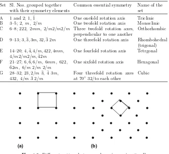
Table 4.2. Seven Crystal Systems Set Sl. Nos. grouped together
with their symmetry elements
Common essential symmetry Name of the set
A 1 and 2; 1, ¯1 One onefold rotation axis Triclinic B 3–5; 2, m, 2/m One twofold rotation axis Monoclinic C 6–8; 222, 2mm, 2/m2/m2/m Three twofold rotation axes,
One fourfold rotation axis Tetrgonal
F 21–27; 6,¯6,6/m, 6mm, 622, ¯
62m, 6/m2/m2/m
One sixfold rotation axis Hexagonal
G 28–32; 23,2/m¯3, ¯4 3m,
Fig. 4.2.Different pattern but same shape (square) unit cell
These seven sets into which the 32 point groups can be regrouped are known as seven crystal systems. There is one common symmetry element between the point groups belonging to each set, that is, crystal systems and they are named as expressed in Table 4.2.
4.3 Crystal Systems
28 4 Crystal Symmetry (Crystal Pattern): I
Table 4.3. Unit cells of seven crystal systems Set Crystal class or systems Relation between
a, bandc
Relation betweenα, β andγ
A Triclinic a=b=c α=β=γ
B Monoclinic a=b=c α=γ= 90◦◦ =β
C Orthorhombic a=b=c α=β=γ= 90◦
D Rhombohedral a=b=c α=β=γ= 90◦
E Tetragonal a=b=c α=β=γ= 90◦
F Hexagonal a=b=c α=β= 90◦, γ= 120◦
G Cubic a=b=c α=β=γ= 90◦
Note: These seven unit cells represent the total number of different ways in which it is possible to draw a parallelepiped. However, it should be mentioned here that the sign=, which means ‘not equal to’ in mathematics, means here usually not equal to by reason of symmetry and accidentally the equality may occur
4.4 Bravais Lattices
Now a question may be raised: “Is it possible to create different patterns two-dimensional or three-dimensional and yet to preserve the same symmetry present in the unit cell, that is, keeping the shape of the unit cells unchanged?” The answer to this question is “yes.” Let us see how this is possible from an example of plane square lattice.
Like this example in plane lattice, in space lattice also by assigning additional lattice points in the unit cells it is possible to create a new three-dimensional pattern but yet keeping the shape of the unit cells unchanged. This assignment of additional lattice points may be done by several possible ways and these result in unit cells as follows:
1. Primitive with only corner lattice points Symbol P 2. Base-centered, i.e., a face-centered Symbol A
Or B face-centered Symbol B
Or C face-centered Symbol C
Or all face-centered Symbol F
3. Body-centered Symbol I
Now as there are seven numbers of crystal systems and there are six numbers of different lattices that could be constructed by assigning additional lattice points like P, A, B, C, F, and I, so it might be possible to find 42 (6×7) different types of space lattices. But we get actually only 14 numbers distinctly different lattices known asBravais lattices.
4.4 Bravais Lattices 29
Table 4.4.The possible Bravais lattices Set Crystal class
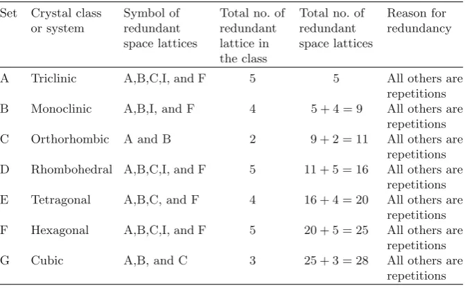
Table 4.5.The redundant space lattices Set Crystal class
A Triclinic A,B,C,I, and F 5 5 All others are repetitions
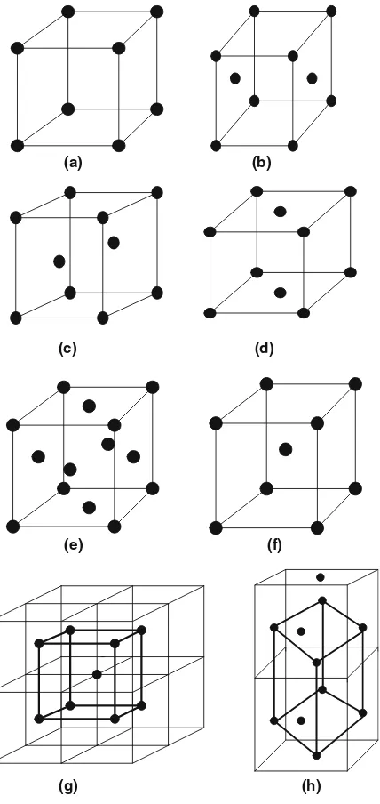
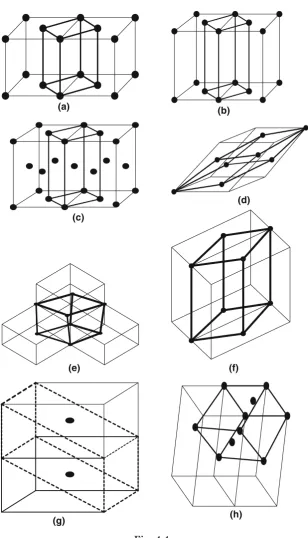
The possible Bravais lattice depends on the fact by the addition of extra lattice sites in the crystal pattern, the pattern changes without changing the basic primitive characteristics [1–3]. A body-centered cubic is a changed pat-tern but lattice represents basically a cubic lattice. It may result in the same lattice but does not repeat with other lattices (Table. 4.5). Figure 4.3 demon-strates this fact. Some examples of the redundant space lattices are shown in Fig. 4.4a–h.
30 4 Crystal Symmetry (Crystal Pattern): I
(a) (b)
(c) (d)
(e) (f)
(g) (h)
Fig. 4.3. (a) Corner sites, primitive symbol: P. (b) A face-centered, symbol: A. (c) B face–centered, symbol: B. (d) C face–centered, symbol: C. (e) All face-centered, symbol: F. (f ) Body–centered, symbol: I. (g) A possible body-centered cubic cell basically remains cubic (bold) a =b=cand α=β=γ = 90◦, yet the
4.4 Bravais Lattices 31
(a) (b)
(c)
(d)
(e) (f)
(g) (h)
32 4 Crystal Symmetry (Crystal Pattern): I
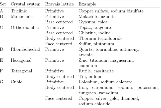
Some important materials as an example of 14 Bravais lattices they belong to are as follows:
Set Crystal system Bravais lattice Example
A Triclinic Primitive Copper sulfate, sodium bisulfate B Monoclinic Primitive Malachite, azunite
Base centered Gypsum, mica C Orthorhombic Primitive Topaz, aragonite
Base centered Chlorine, iodine Body centered Thorium tetrafluoride Face centered Sulfur, plutonium
D Rhombohedral Primitive Quartz, tourmaline, antimony, arsenic
E Hexagonal Primitive Zinc, titanium, magnesium, cadmium
F Tetragonal Primitive Rutile, cassiterite Body centered Tin, indium
G Cubic Primitive Polonium, sodium chlorate
Body centered Iron, chromium, sodium, potassium, tungsten, vanadium
Face centered Copper, silver, gold, diamond, sodium chloride
The number of lattice points,N (atoms or molecules in actual crystals), in a Unit Cell is given by N = 1 + (1/2)f +b, wheref and bstand for number of
points in the centre of the faces and at the centre of the body of the unit cell.
←−−−−−−−−−−−−−−−−−−−−−−−−−−−−−−−−−−−−−−−−−−−−−−−−−−−−−−−−−−−−−−−− Fig. 4.4.(Continued)(a)The addition of base-centered points in cubic cell results in primitive tetragonal space lattice. The resultant lattice is shown by heavy lines. a=b=cand α=β=γ = 90◦. The resultant tetragonal lattice is shown bybold
References 33
A primitive cubic lattice unit cell has atoms at the corners but each one of them is shared by eight neighboring unit cells and therefore the total contri-bution of corner atoms is equivalent to only one. A body-centered cubic unit cell has only two (f = 0) and a face-centered cubic unit cell has four, one due to eight corner points and three due to centre points on each of six faces. These face centered points are shared by two neighboring unit cells.
4.5 Summary
1. Crystal symmetry considers the scheme of positional repetitions as well as the influence of motifs on the symmetry.
2. When the existence of the motifs is only considered on planes in three-dimensional crystal, the different patterns that can be created are called “point groups”.
3. There can be only 32 of such point groups as more than that will be a duplication of the one that already exists.
4. These 32 point groups can be grouped into seven different classes, each having different shapes of the unit cells.
5. A creation of additional lattice points without disturbing the class makes 14 different types of patterns, which appears different as a whole but basically remains in the same class and they are known as Bravais lattices.
References
1. L.V. Azaroff,Introduction to Solids(Mc Graw Hill, New York, 1960) 2. M.J. Buerger,X-ray Crystallography(Wiley, New York, 1942)
5
Crystal Symmetry (Crystal Pattern): II
5.1 Microscopic Symmetry Elements in Crystals
So far we have discussed the macroscopic symmetry elements that are mani-fested by the external shape of the three-dimensional patterns, that is, crys-tals. They can be studied by investigating the symmetry present in the faces of the crystals. In addition to these symmetry elements there are two more sym-metry elements that are related to the detailed arrangements of motifs (atoms or molecules in actual crystals). These symmetry elements are known as mi-croscopic symmetry elements, as they can only be identified by the study of internal arrangement of the motifs. As X-ray or electron diffraction can reveal the internal structures, these symmetry arrangements can only be identified by X-ray, Electro or Neutron diffraction. Obviously, they are not revealed in the external shape of the pattern. These symmetry elements are classified as microscopic symmetry elements. There are two such types of symmetry elements: (i) glide plane of symmetry and (ii) screw axis of symmetry.
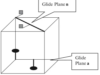
Glide plane of symmetry: It is a combination of reflection and translation of the motif. It is explained by Fig. 5.1. Figure 5.2 shows simple pattern of a glide plane.
The translation associated with the glide plane may be one of the following (Fig. 5.3):
(i) One half of one of the unit translational vectors, that is, a, b, and c, which define the unit cell
(ii) One half or one quarter of the face diagonal
Hermann–Mauguin symbol of glide plane of symmetry: Reflection + translationa/2 symbol = a
Reflection + translationb/2 symbol = b Reflection + translationc/2 symbol = c Reflection +1/2face diagonal symbol = n
36 5 Crystal Symmetry (Crystal Pattern): II
a
g a/2
Fig. 5.1. a is the unit translational vector. The motif suffers a reflection on the mirror plane and undergoes a translation half the way.g the mirror perpendicular to the diagram and is known as the glide plane
╔
╔
╔
╔
╚
╚
╚
Fig. 5.2.A border showing simple glide plane of symmetry
Glide Plane n
Glide Plane a Fig. 5.3.Reflection and1/
2translation along a, “a” glide, and along face diagonal,
“n” glide
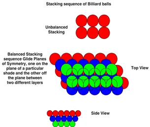
There are plenty of natural examples: The stacking sequence of the close-packed planes, that is, {111} sets of planes in face-centered lattice (fcc) are known as ABC. . .. The entire scenario of stacking of these close-packed planes can be viewed as the stacking of hard billiard balls one over the other (Fig. 5.4). It can be easily visualized that a layer of such balls can never be placed exactly vertically at the top as the arrangement has to get toppled. To make a stable arrangement, the balls of one layer have to be placed on the gaps of the balls in the lower layer. This can be understood from the diagram as below.
5.1 Microscopic Symmetry Elements in Crystals 37
Side View Unbalanced
Stacking
Stacking sequence of Billiard balls
Top View Balanced Stacking
sequence Glide Planes of Symmetry, one on the
plane of a particular shade and the other off
the plane between two different layers
Fig. 5.4. The balanced stacking sequence of Billiard balls: red is the first layer,
bluethe second, andgreen the third. The fourth layer shown by open circle is the repetition of the first layer, that is, it can stay exactly over first layer. Each layer of first to third has suffered a glide in the plane over them
Note: A glide plane is a plane across which mirror reflection combined with a translation transforms an array of motifs into self coincidence. This stacking sequence shown above for Billiard balls has an important resemblance with that of stacking sequence of crystal planes discussed later.
Screw Axis of Symmetry: It is the combined effect of rotation and translation, which transforms the array of motifs into self coincidence. The rotation axis is known as screw axis of rotational symmetry or simply screw axis of symmetry (Figs. 5.5 and 5.6).
Note: A screw axis of symmetry is an axis about which a rotation combined with translation parallel to the axis transforms an array of motifs into self coincidence.
38 5 Crystal Symmetry (Crystal Pattern): II
X
a
a/2
X/
Fig. 5.5. A twofold rotation and half translationa/2 along the rotation axis XX; Symbol: 21
Fig. 5.6.A right handed screw in three dimension
Like this, if we consider all the possible rotation axes of symmetries and the possible translations along the rotation axis, henceforth known as screw axis, we get eleven different types of Screw axes of symmetries. They are listed in Table 5.1.
5.1 Microscopic Symmetry Elements in Crystals 39
Table 5.1. Eleven different types of screw axes of symmetries Rotation axis Translation: fraction of the distance between
lattice points in the direction of the axis
Symbol
(Hermann–Mauguin)
2 1/2 21
3 1/3 31
3 2/3 32
4 1/4 41
4 1/2 42
4 3/4 43
6 1/6 61
6 1/3 62
6 1/2 63
6 2/3 64
6 5/6 65
within the three-dimensional patterns (crystals) and involving a translation operation. They are detectable only by X-ray diffraction methods and hence the name “microscopic symmetry.” They can only be manifested in space and so they are called spatial symmetry. These elements consist of FIVE different kinds of GLIDE planes and ELEVEN different types of SCREW AXIS.
It now can be appreciated those only symmetry elements that might be present in the structure of any crystal which is nothing but a three-dimensional pattern are the following:
Macroscopic symmetry Mirror planem
Centre of symmetry ¯1 Rotation axis 1, 2, 3, 4, 6 Rotary inversion ¯3,¯4,¯6
Microscopic symmetry Glide plane a, b, c, n, d Screw axis 21,31,32,41,42,43
61,62,63,64,65
The detailed information about the symmetry properties of the complete array of atoms or molecules in a crystal can be obtained only from the com-bined specifications of the symmetry at a lattice point, that is, the point groups modified by the microscopic translational symmetry and the distribution in space (Bravais lattice) of those points.
Such combination demonstrates the full description of the symmetry ele-ments present in any crystal and it is named asspace group[1, 2].
40 5 Crystal Symmetry (Crystal Pattern): II
5.2 Space Groups
Therefore, a space group is a possible combination of all the symmetry ele-ments, macroscopic and microscopic, in space of the Bravais lattice and can be derived. It is found that when all such symmetry elements are combined and applied in the Bravais lattices, 230 different types of crystal space lattices are possible. It is appropriate to mention here that any crystal either naturally free grown or crystallized artificially from the solutions of the synthesized com-pounds must belong to any of these possible 230 types of space groups [1, 2].
Note: The Hermann–Mauguin space group notation for any particular crystal comprises two parts. The first part identifies the Bravais lattice type into which the crystal belongs and the second part identifies the total symmetry of the array of atoms in the crystal and therefore also the crystal system. In the second part that identifies the symmetry, only those symmetry elements are included in the symbol that are necessary to describe the space group uniquely. The remainders are being omitted since they follow, as a necessary consequence.
Example:
Pm m m= Primitive lattice, three mirror planes at right angles.
P n m a = Primitive lattice, glide plane (n), that is, 1/2 diagonal
face (b/2 + c/2) and perpendicular to a axis, mirror plane perpendicu-lar to b axis, and finally another glide plane (a) perpendicular to c axis with translation a/2. The same space group oriented differently might be Pn a m, Pb n m, Pc m n, Pm n b, and Pm c n.
Fm 3 m = Face centered, mirror plane along a, threefold rotation axis alongb, and another mirror plane alongcaxis.
It is instructive to derive a few space groups as follows:
Triclinic System: There is possibility of the existence of only one primitive P lattice. It has two point groups 1 and 1-bar, that is, onefold rotation and a centre of symmetry and these are the only ways in which the symmetry elements can occur in triclinic system. These two combinations, i.e., P 1 and P ¯1 are two space groups of the triclinic system.
Monoclinic System: It has two Bravais lattices, i.e., primitive (P) and base-centered C, and three point groups 2,m, and 2/m. In detailed study of sym-metry, the array of atoms that constitutes the structure of the crystal, a macroscopic mirror plane m, might be a glide plane c, while twofold rota-tion axis might be a screw axis as 21. Considering these aspects of possible
symmetry, the complete set is given as follows:
1. A twofold rotation axis in P and C lattices = P2, C2 2. A 21 screw axis in P and C lattices = P21, C21
3. A mirror plane in P and C lattices = Pm, Cm
5.2 Space Groups 41
5. A twofold axis and mirror plane in P and C = P2/m, C2/m
6. A 21 screw axis and mirror plane in P and C = P21/m, C21/m
7. A twofold axis and a glide planecin P and C = P2/c, C2/c
8. A 21 screw axis and glide planec in P and C = P21/c, C21/c
However, out of these 16 numbers of combinations as mentioned above do not specify different arrays of symmetry elements in space, as C2 and C21
are identical and combinations C21/c and C2/c are also identical. So, there
can be only thirteen (13) different combinations of symmetry elements that can occur in the array of atoms in a monoclinic system and so the monoclinic system has 13 space groups.
Note: When all possible but different combinations of symmetry elements present between array of atoms in seven crystal systems are added together, we get 230 number of space groups (Table 5.2).
These 230 space groups are the only ways in which different distribution of compatible combinations of macroscopic and microscopic symmetry elements can occur in the array of atoms in any crystal.
In reading a space group notation it is important to remember the following:
A onefold axis includes the elements 1, ¯1
A twofold axis includes the elements 2, 21,m, a, b, c, n, d
A threefold axis includes the elements 3, ¯3, 31, 32
A fourfold axis includes the elements 4, ¯4, 41, 42, 43
A sixfold axis includes the elements 6, ¯6, 61, 62, 63, 64, 65;
these may further be noted that the existence of onefold axes denote the triclinic system,
onetwofold axis denotes the monoclinic system,
threetwofold axes at right angles denote the orthorhombic system, onethreefold axis denotes the rhombohedra system,
fourthreefold axes at 70◦
32/to one another denote the cubic system, onefourfold axis denotes the tetragonal system, and
onesixfold axis denotes the hexagonal system.
Table 5.2. Possible space groups System No of space group
Triclinic 2
Monoclinic 13
Orthorhombic 59 Rhombohedral 25
Hexagonal 27
Tetragonal 68
Cubic 36
42 5 Crystal Symmetry (Crystal Pattern): II
5.3 Constitution of Space Groups
The detailed study to know how these space groups are constituted from seven crystal systems is out of the scope of this book. Mathematically it can be derived from the group theory and geometrically, the derivation of all these 230 space groups is cumbersome and therefore, for only one crystal system, that is, for monoclinic system the procedure that is adopted is explained below.
A particular crystal system has some definite number of point groups and for this monoclinic system it has symmetry operations like 2,m, and 2/m, that is, twofold rotation, a mirror plane, and twofold with mirror plane of symme-tries. Now, for three-dimensional crystal the possible symmetry elements will include also screw axes and glide planes, and when screw axes and glide planes are added to the point group of symmetries for this system, we can say that different possibilities that may exist are 2, 21, m, c, 2/m, 21/m, 2/c, and
21/c. Now each of these symmetry groups are repeated by lattice translation
of the Bravais lattices of that system. As monoclinic system has only primitive P and C, all the symmetry possibilities may be associated with both P and C. Therefore, if they are worked out, they come out to be 13 in number and they are Pm, Pc, Cm, Cc, P2, P21, C2, P2/m, P21/m, C2/m, P2/c, P21/c,
C2/c, etc.
Similarly the space groups of all the crystal systems can be worked out and these come out to be as mentioned earlier 230 in number.
5.4 Summary
1. When two more symmetry operations move the motifs out from their orig-inal plane on which they origorig-inally exist, more lattice patterns are created. 2. These symmetry operations are called microscopic symmetry operations as they can only be identified from internal structure of the crystal lattice in three dimensions and not by the geometrical shape of the crystal.
3. The number of possible patterns comprising the lattice sites not confined on a plane will then increase to 230 and these lattices are called “space groups.”
References
1. M.J. Buerger,X-ray Crystallography(Wiley, New York, 1966)
6
Crystals and X-Ray
X-ray was discovered by the German Physicist Roentgen in 1895 almost acci-dentally while performing experiments on the discharge of electricity through gases under low pressure. Another German Physicist Von Laue’s discovery of regular diffraction pattern when X-ray was diffracted by single crystals opened a new year of crystal structure analysis. It is only after the Von Laue’s famous experiment; it was proved that the crystallinity of a solid depends on the reg-ular arrangement of the constituent atoms or molecules in three-dimensional space and not on the external features. It should also be known that the wave-length of X-ray radiation varies between∼1 and∼3 ˚A, which is the order of interatomic distances of the solids and that is why X-ray satisfies the diffrac-tion condidiffrac-tions. In addidiffrac-tion to that of X-ray, there are two other methods of analysis of crystallinity of materials and they are electron and neutron dif-fraction. These three techniques have their own advantages and limitations and in essence complement one another.
6.1 Production and Properties of X-Ray
44 6 Crystals and X-Ray
K-shell
Ka Kb L-shell
Potential Energy
M-shell Ground state
Fig. 6.1. Emission of Kαand Kβ
AC
Cu backing X-ray
through Be windows Spec pure Target Metal
Fig. 6.2. X-ray tube (sealed type) showing target metal, cooling device, and the filament for electron emission
of the target atoms. These processes emit radiation of specific wavelengths which are characteristic of the target atom as they depend on the atomic number (Z) of the atoms of the target. These radiations being dependent on the atomic number are named ascharacteristic radiation[1, 2].
6.2 Laue Equations 45
I n t e n s i t y
Wave Length (Ao) Kβ
Kα
K absorption edge
Fig. 6.3.X-ray spectra from Cu target and the position of K absorption edge of Ni used as Kβfilter for Cu radiation
radiation, balanced filters (Ross filters) or crystal monochromators are used. The crystal monochromator and absorption edges of these balanced filters are shown in Fig. 6.4a, b.
6.2 Laue Equations
It has been stated before that the Laue diffraction pattern from single crystals was the beginning of the idea that the internal regular arrangement of atoms in space is responsible for the crystallinity of the material. Figure 6.5 shows the X-ray diffraction from a row of atoms.
Now, when the path difference between incident and diffracted beams be-comes equal to the integral multiple of the wavelengthλ, then the interference maxima condition will be satisfied, i.e., BC−AD =acosθ−acosϕ= nλ, this is one-dimensional Laue equation. When the other two directions are considered, then the corresponding Laue equations are
b cosθ′
−b cosϕ′
=nλ and c cosθ′′
−c cosϕ′′
=nλ.
In vector form, these three Laue equations can be written as
a·(S−S0) =nλ, b·(S−S0) =nλ, and c·(S−S0) =nλ.
46 6 Crystals and X-Ray
Li F Crystal on rotating base
Counter
Crystal Monochromator
Diffracted X-ray From Sample
Cu Kα
Ni and Co
Ni & Co Co
Pass Band
λ (AO)
IO Ix mx = −ln
Ni
Balanced Filter : Ross Filter : Ni & Co combination for Cu Kα radiation
Fig. 6.4. (a) Crystal monochromator. LiF single crystals can diffract like other crystals, Kα and Kβ radiations from any target at specific angles and the counter
placed at such angles will only record the diffraction pattern due to that wavelength and that without reducing the intensity of the radiation and reducing considerably the background. This is the major advantage of crystal monochromator now attached invariably with diffractometer. (b) Ross filter. As mass absorption coefficient is dependent onλ3