AMVS
Advanced MPLS
VPN Solutions
Volume 2
Version 1.0Student Guide
The products and specifications, configurations, and other technical information regarding the products in this manual are subject to change without notice. All statements, technical information, and recommendations in this manual are believed to be accurate but are presented without warranty of any kind, express or implied. You must take full responsibility for their application of any products specified in this manual.
LICENSE
PLEASE READ THESE TERMS AND CONDITIONS CAREFULLY BEFORE USING THE MANUAL, DOCUMENTATION, AND/OR SOFTWARE (“MATERIALS”). BY USING THE MATERIALS YOU AGREE TO BE BOUND BY THE TERMS AND CONDITIONS OF THIS LICENSE. IF YOU DO NOT AGREE WITH THE TERMS OF THIS LICENSE, PROMPTLY RETURN THE UNUSED MATERIALS (WITH PROOF OF PAYMENT) TO THE PLACE OF PURCHASE FOR A FULL REFUND.
Cisco Systems, Inc. (“Cisco”) and its suppliers grant to you (“You”) a nonexclusive and nontransferable license to use the Cisco Materials solely for Your own personal use. If the Materials include Cisco software
(“Software”), Cisco grants to You a nonexclusive and nontransferable license to use the Software in object code form solely on a single central processing unit owned or leased by You or otherwise embedded in equipment provided by Cisco. You may make one (1) archival copy of the Software provided You affix to such copy all copyright, confidentiality, and proprietary notices that appear on the original. EXCEPT AS EXPRESSLY AUTHORIZED ABOVE, YOU SHALL NOT: COPY, IN WHOLE OR IN PART, MATERIALS; MODIFY THE SOFTWARE; REVERSE COMPILE OR REVERSE ASSEMBLE ALL OR ANY PORTION OF THE SOFTWARE; OR RENT, LEASE, DISTRIBUTE, SELL, OR CREATE DERIVATIVE WORKS OF THE MATERIALS.
You agree that aspects of the licensed Materials, including the specific design and structure of individual programs, constitute trade secrets and/or copyrighted material of Cisco. You agree not to disclose, provide, or otherwise make available such trade secrets or copyrighted material in any form to any third party without the prior written consent of Cisco. You agree to implement reasonable security measures to protect such trade secrets and copyrighted Material. Title to the Materials shall remain solely with Cisco.
This License is effective until terminated. You may terminate this License at any time by destroying all copies of the Materials. This License will terminate immediately without notice from Cisco if You fail to comply with any provision of this License. Upon termination, You must destroy all copies of the Materials.
Software, including technical data, is subject to U.S. export control laws, including the U.S. Export Administration Act and its associated regulations, and may be subject to export or import regulations in other countries. You agree to comply strictly with all such regulations and acknowledge that it has the responsibility to obtain licenses to export, re-export, or import Software.
This License shall be governed by and construed in accordance with the laws of the State of California, United States of America, as if performed wholly within the state and without giving effect to the principles of conflict of law. If any portion hereof is found to be void or unenforceable, the remaining provisions of this License shall remain in full force and effect. This License constitutes the entire License between the parties with respect to the use of the Materials
Restricted Rights - Cisco’s software is provided to non-DOD agencies with RESTRICTED RIGHTS and its supporting documentation is provided with LIMITED RIGHTS. Use, duplication, or disclosure by the U.S. Government is subject to the restrictions as set forth in subparagraph “C” of the Commercial Computer Software - Restricted Rights clause at FAR 52.227-19. In the event the sale is to a DOD agency, the U.S. Government’s rights in software, supporting documentation, and technical data are governed by the restrictions in the Technical Data Commercial Items clause at DFARS 252.227-7015 and DFARS 227.7202.
DISCLAIMER OF WARRANTY. ALL MATERIALS ARE PROVIDED “AS IS” WITH ALL FAULTS. CISCO AND ITS SUPPLIERS DISCLAIM ALL WARRANTIES, EXPRESSED OR IMPLIED, INCLUDING, WITHOUT LIMITATION, THOSE OF MERCHANTABILITY, FITNESS FOR A PARTICULAR PURPOSE AND NONINFRINGEMENT OR ARISING FROM A COURSE OF DEALING, USAGE, OR TRADE PRACTICE.
the FCC rules. These specifications are designed to provide reasonable protection against such interference in a residential installation. However, there is no guarantee that interference will not occur in a particular
installation.
You can determine whether your equipment is causing interference by turning it off. If the interference stops, it was probably caused by the Cisco equipment or one of its peripheral devices. If the equipment causes
interference to radio or television reception, try to correct the interference by using one or more of the following measures:
• Turn the television or radio antenna until the interference stops. • Move the equipment to one side or the other of the television or radio. • Move the equipment farther away from the television or radio.
• Plug the equipment into an outlet that is on a different circuit from the television or radio. (That is, make certain the equipment and the television or radio are on circuits controlled by different circuit breakers or fuses.) Modifications to this product not authorized by Cisco Systems, Inc. could void the FCC approval and negate your authority to operate the product.
The following third-party software may be included with your product and will be subject to the software license agreement:
CiscoWorks software and documentation are based in part on HP OpenView under license from the Hewlett-Packard Company. HP OpenView is a trademark of the Hewlett-Hewlett-Packard Company. Copyright © 1992, 1993 Hewlett-Packard Company.
The Cisco implementation of TCP header compression is an adaptation of a program developed by the University of California, Berkeley (UCB) as part of UCB’s public domain version of the UNIX operating system. All rights reserved. Copyright © 1981, Regents of the University of California.
Network Time Protocol (NTP). Copyright © 1992, David L. Mills. The University of Delaware makes no representations about the suitability of this software for any purpose.
Point-to-Point Protocol. Copyright © 1989, Carnegie-Mellon University. All rights reserved. The name of the University may not be used to endorse or promote products derived from this software without specific prior written permission.
The Cisco implementation of TN3270 is an adaptation of the TN3270, curses, and termcap programs developed by the University of California, Berkeley (UCB) as part of UCB’s public domain version of the UNIX operating system. All rights reserved. Copyright © 1981-1988, Regents of the University of California.
Cisco incorporates Fastmac and TrueView software and the RingRunner chip in some Token Ring products. Fastmac software is licensed to Cisco by Madge Networks Limited, and the RingRunner chip is licensed to Cisco by Madge NV. Fastmac, RingRunner, and TrueView are trademarks and in some jurisdictions registered trademarks of Madge Networks Limited. Copyright © 1995, Madge Networks Limited. All rights reserved. XRemote is a trademark of Network Computing Devices, Inc. Copyright © 1989, Network Computing Devices, Inc., Mountain View, California. NCD makes no representations about the suitability of this software for any purpose.
Table of Contents
Volume 1
ADVANCED MPLS VPN SOLUTIONS 1-1
Overview 1-1
Course Objectives 1-2
Course Objectives – Implementation 1-3
Course Objectives – Solutions 1-4
Prerequisites 1-5
Participant Role 1-7
General Administration 1-9
Sources of Information 1-10
MPLS VPN TECHNOLOGY 2-1
Overview 2-1
Objectives 2-1
Introduction to Virtual Private Networks 2-2
Objectives 2-2
Summary 2-8
Review Questions 2-8
Overlay and Peer-to-Peer VPN 2-9
Objectives 2-9
Overlay VPN Implementations 2-13
Summary 2-23
Review Questions 2-24
Major VPN Topologies 2-25
Objectives 2-25
VPN Categorizations 2-25
Summary 2-38
Review Questions 2-38
MPLS VPN Architecture 2-39
Objectives 2-39
Summary 2-60
Major VPN Topologies 2-94
MPLS VPN Architecture 2-94
MPLS VPN Routing Model 2-95
MPLS VPN Packet Forwarding 2-96
MPLS/VPN CONFIGURATION ON IOS PLATFORMS 3-1
Overview 3-1
Objectives 3-1
MPLS/VPN Mechanisms in Cisco IOS 3-2
Objectives 3-2
Summary 3-16
Review Questions 3-16
Configuring Virtual Routing and Forwarding Table 3-17
Objectives 3-17
Summary 3-26
Review Questions 3-26
Configuring a Multi-Protocol BGP Session Between the PE Routers 3-27
Objectives 3-27
Summary 3-43
Review Questions 3-43
Configuring Routing Protocols Between PE and CE Routers 3-44
Objectives 3-44
Summary 3-55
Review Questions 3-55
Monitoring MPLS/VPN Operation 3-56
Objectives 3-56
Advanced VRF Import/Export Features 3-101
Objectives 3-101
Summary 3-115
Review Questions 3-115
Advanced PE-CE BGP Configuration 3-116
Summary 4-36
Answers to Review Questions 4-37
Using OSPF as the PE-CE Protocol in an MPLS VPN Environment 4-37 Configuring and Monitoring OSPF in an MPLS VPN Environment 4-37
Volume 2
MPLS VPN TOPOLOGIES 5-1
Overview 5-1
Objectives 5-1
Simple VPN with Optimal Intra-VPN Routing 5-2
Objectives 5-2
Summary 5-17
Review Questions 5-17
Using BGP as the PE-CE Routing Protocol 5-18
Objectives 5-18
Summary 5-23
Review Questions 5-23
Overlapping Virtual Private Networks 5-24
Objectives 5-24
Summary 5-33
Review Questions 5-33
Central Services VPN Solutions 5-34
Objectives 5-34
Summary 5-47
Review Questions 5-47
Hub-andSpoke VPN Solutions 5-48
Objectives 5-48
Summary 5-54
Review Questions 5-54
Managed CE-Router Service 5-55
Objectives 5-55
Integrating Internet Access with the MPLS VPN Solution 6-2
Separating Internet Access from VPN Service 6-39
Objectives 6-39
Usability of Separated Internet Access for Various Internet
Access Services 6-44
Summary 6-46
Review Questions 6-46
Internet Access Backbone as a Separate VPN 6-47
Objectives 6-47
Usability of Internet in a VPN Solution for Various Internet
Access Services 6-52
Backbone and PE-CE Link Addressing Scheme 7-2
Objectives 7-2
Summary 7-15
Review Questions 7-16
Backbone IGP Selection and Design 7-17
Objectives 7-17
Summary 7-30
Review Questions 7-31
Route Distinguisher and Route Target Allocation Schemes 7-32
Objective 7-32
Summary 7-37
Review Questions 7-37
End-to-End Convergence Issues 7-38
Objectives 7-38
Summary 7-52
Review Questions 7-52
Chapter Summary 7-53
Answers to Review Questions 7-54
Backbone and PE-CE Link Addressing Scheme 7-54 Backbone IGP Selection and Design 7-55 Route Distinguisher and Route Target Allocation Scheme 7-56
End-to-End Convergence Issues 7-56
LARGE-SCALE MPLS VPN DEPLOYMENT 8-1
Overview 8-1
Objectives 8-1
MPLS VPN MIGRATION STRATEGIES 9-1
Customer Migration to MPLS VPN service 9-10
Objective 9-10
Generic Customer Migration Strategy 9-11 Migration From Layer-2 Overlay VPN 9-13 Migration from GRE Tunnel-Based VPN 9-16
Migration from IPSec-Based VPN 9-19
Migration from L2F-Based VPN 9-20
Migration From Unsupported PE-CE Routing Protocol 9-22
Summary 9-26
Review Questions 9-26
Chapter Summary 9-26
INTRODUCTION TO LABORATORY EXERCISES A-1
Overview A-1
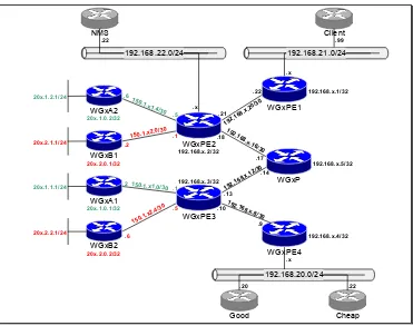
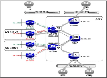
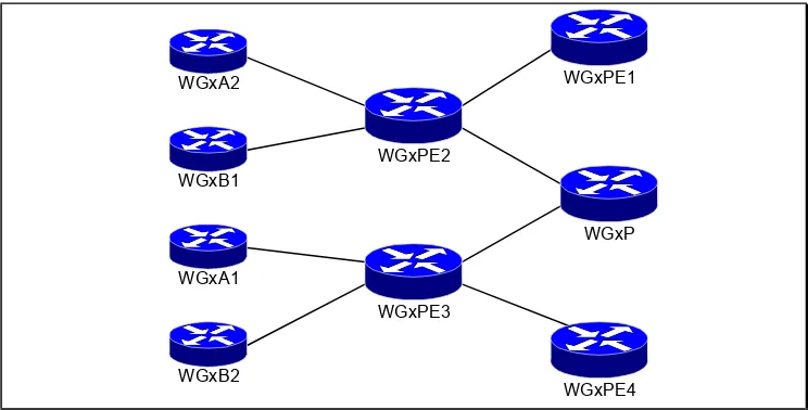
Physical And Logical Connectivity A-2
IP Addressing Scheme A-5
Initial BGP Design A-7
Notes Pages A-8
LABORATORY EXERCISES—FRAME-MODE MPLS CONFIGURATION B-1
Overview B-1
Laboratory Exercise B-1: Basic MPLS Setup B-2
Objectives B-2
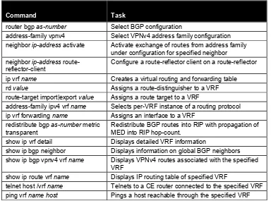
Command list B-2
Task 1: Configure MPLS in your backbone B-2 Task 2: Remove BGP from your P-routers B-2
Verification: B-3
Review Questions B-4
Laboratory Exercise B-2: Disabling TTL Propagation B-5
LABORATORY EXERCISES—MPLS VPN IMPLEMENTATION C-1
Overview C-1
Laboratory Exercise C-1: Initial MPLS VPN Setup C-2
Objectives C-2
Background Information C-2
Command list C-3
Task 1: Configure multi-protocol BGP C-3 Task 2: Configure Virtual Routing and Forwarding Tables C-4
Additional Objective C-5
Task 3: Configuring Additional CE routers C-5
Verification C-6
Laboratory Exercise C-2: Running OSPF Between PE and CE Routers C-9
Objectives C-9
Visual Objective C-9
Command list C-10
Task 1: Configure OSPF on CE routers C-10 Task 2: Configure OSPF on PE routers C-10
Verification C-11
Task 3: Configure OSPF connectivity with additional CE routers C-11
Verification C-12
Laboratory Exercise C-3: Running BGP Between the PE and CE Routers C-13
Objectives C-13
Background Information C-13
Command list C-14
Task 1: Configure Additional PE-CE link C-14 Task 2: Configure BGP as the PE-CE routing protocol C-14
Verification C-15
Task 3: Select Primary and Backup Link with BGP C-16
Verification: C-16
Task 4: Convergence Time Optimization C-17
Verification C-17
LABORATORY EXERCISES—MPLS VPN TOPOLOGIES D-1
Overview D-1
Laboratory Exercise D-1: Overlapping VPN Topology D-2
Objective D-2
Visual Objective D-2
Command list D-3
Task 1: Design your VPN solution D-4
Task 2: Remove WGxA1/WGxB1 from existing VRFs D-4 Task 3: Configure new VRFs for WGxA1 and WGxB1 D-4
Verification: D-4
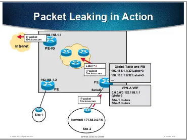
Verification D-13 Laboratory Exercise D-3: Internet Connectivity Through Route Leaking D-14
Objective D-14
Visual Objective D-14
Command list D-15
Task 1: Cleanup from the previous VPN exercises D-15 Task 2: Configure route leaking between customer VPN and
the Internet D-15
Verification D-16
Additional exercise: Fix intra-VPN routing D-17 Laboratory Exercise D-4: Separate Interface for Internet Connectivity D-18
Objective D-18
Visual Objective D-19
Command list D-20
Task 1: Cleanup from the previous exercise D-20
Verification D-21
Task 2: Establishing connectivity in the global routing table D-21 Task 3: Routing between the PE-router and the CE-router D-21
Verification D-22
Laboratory Exercise D-5: Internet in a VPN D-23
Objective D-23
Visual Objective D-23
Command list D-24
Task 1: Design your Internet VPN D-24
Task 2: Migrate Internet routers in a VPN D-24
Verification D-25
Additional Task: Direct Internet connectivity for all CE-routers D-26
Verification D-26
INITIAL LABORATORY CONFIGURATION E-1
Overview E-1
Laboratory Exercise E-1: Initial Core Router Configuration E-2
Objective E-2
Task: Configure Initial Router Configuration E-2
Verification E-3
Laboratory Exercise E-2: Initial Customer Router Configuration E-4
Objective E-4
Task: Configure Customer Routers E-4
Verification E-5
Laboratory Exercise E-3: Basic ISP Setup E-6
Objective E-6
Router WGxPE3 F-6
Router WGxPE4 F-8
Router WGxP F-10
Router WGxA1 F-12
Router WGxA2 F-14
Router WGxB1 F-15
5
MPLS VPN Topologies
Overview
This chapter describes the most commonly used MPLS VPN topologies and the design and implementation issues associated with them.
It includes the following topics:
■ Simple VPN with optimal Intra-VPN routing
■ Using BGP as the PE-CE routing protocol
■ Overlapping Virtual Private Networks
■ Central Services VPN solutions
■ Hub-and-Spoke VPN solutions
■ Managed CE Router Service
Objectives
Simple VPN with Optimal Intra-VPN Routing
Objectives
Upon completion of this section, you will be able to perform the following tasks:
■ Describe the requirements of simple VPN solutions
■ Describe the routing model of these solutions
■ Describe the optimal intra-VPN routing data flow
■ Select the optimal PE-CE routing protocol based on user requirements
■ Integrate the selected PE-CE routing protocol with the MPLS VPN backbone
© 2000, Cisco Systems, Inc. www.cisco.com Chapter 1-5
MPLS backbone
Simple VPN
Requirements Summary
Simple VPN
Requirements Summary
•
Any site router can talk to any other site
•
Optimum routing across P-network is desired
P-network
PE-1 PE-2
CE-Spoke
CE-Spoke
CE-Spoke
CE-Spoke
© 2000, Cisco Systems, Inc. www.cisco.com Chapter 1-6
Simple VPN
Routing and Data Flow
Simple VPN
Routing and Data Flow
•
Each site needs to reach every other site in
the same VPN
•
Each VRF belonging to simple VPN contains all
VPN routes
•
The sites use default route or have full routing
knowledge of all other sites of same VPN
•
Data flow is optimal in the backbone
•
Routing between PE routers is done based on
MP-BGP Next-Hop closest to the destination
•
No site is used as central point for
connectivity
MPLS VPN architecture by default provides optimal routing between CE sites. A CE site can have full internal routing for its VPN or just a default route pointing to the PE router. The PE routers, however, need to have full routing information for the MPLS VPN network in order to provide connectivity and optimal routing. A MP-BGP next-hop address is used to find a label for a VPN destination
© 2000, Cisco Systems, Inc. www.cisco.com Chapter 1-7
MPLS backbone
Simple VPN - Routing
Information Propagation
Simple VPN - Routing
Information Propagation
•CE routers announce the customer routes to the PE routes
•Customer routes are redistributed into MP-BGP
•VPNv4 routes are propagated across P-network with the BGP next-hop of the ingress PE router (PE-1)
•VPNv4 routes are inserted into target VRF based on route-target and redistributed back into the customer routing protocol
•Customer routes are propagated to other CE routers
When a Customer Edge (CE) router announces a network through an IGP, the PE router will redistribute and export it into Multiprotocol BGP, converting an IPv4 address into a VPNv4 address. The following list contains the most significant changes that happen with redistribution and export:
■ IPv4 Network Layer Reachability Information (NLRI) is converted into
VPNv4 NLRI by pre-pending a route distinguisher (for example, a route distinguisher 12:13 could be prepended to an IPv4 prefix 10.0.0.0/8 resulting in a VPNv4 prefix 12:13:10:10.0.0.0/8)
Note NLRI is a BGP term for a prefix (address and subnet mask)
■ VPNv4 NLRI also contains a label that will be used to identify the outgoing
interface or the VRF where a routing lookup should be performed
■ A route target extended community is added based on the VRF configuration
© 2000, Cisco Systems, Inc. www.cisco.com Chapter 1-8
MPLS backbone
Simple VPN
Data Flow
Simple VPN
Data Flow
P-network
PE-1 PE-2
CE-Spoke
CE-Spoke
CE-Spoke
CE-Spoke
•Ingress CE forwards the data packet based on route received from PE-2 and propagates the packet toward PE-2
•PE-1 forwards the data packet based on route received from egress CE router
•PE-2 forwards the data packet based on the MP-BGP route with PE-1 as the BGP next-hop. Data flow with the P-network is optimal
In the slide above, the CE router finds the destination in its IP routing table (learned through IGP or based on a static default route). PE-2 has learned about the destination through MP-BGP and labels each packet from the CE router with the VPN label (second label) and the next-hop label (top label).
The core routers are doing label switching based on the top label. The last core router before PE-1 will pop the top label (penultimate hop popping). PE-1 will identify the outgoing interface or the VRF by looking at the second label, which at this time is the top and only label. The packet sent to the CE is no longer labeled.
© 2000, Cisco Systems, Inc. www.cisco.com Chapter 1-9
MPLS backbone
Simple VPN – Basic Design
Rules
Simple VPN – Basic Design
Rules
•
Configure only one VRF per PE router
•
Configure the same Route Distinguisher on all
VRFs
•
Configure one import/export route target
P-network
PE-1 PE-2
CE-Spoke
CE-Spoke
CE-Spoke
CE-Spoke
To optimize performance, reduce configuration efforts and conserve memory on the PE router on which you should minimize the number of VRFs per router.
Using one VRF per VPN per PE router will reduce memory requirements and CPU load. This is possible because the routing requirements for all CE routers in the same VPN are the same. Using one VRF per VPN can also improve
convergence between CE routers connected to the same PE router.
Using the same route distinguisher for VRFs that are used for the same VPN will also conserve memory.
Only one route target is needed for a simple VPN. Any additional route targets are unnecessary and will consume at least 64 bits per routing update.
© 2000, Cisco Systems, Inc. www.cisco.com Chapter 1-10
MPLS backbone
P-network
PE-1 PE-2 CE-Spoke
CE-Spoke
CE-Spoke
CE-Spoke
Simple VPN – VRF
Configuration
Simple VPN – VRF
Configuration
ip vrf VPN_A rd 213:750
route-target both 213:750 !
interface Serial0/0 ip vrf forwarding VPN_A
ip address 192.168.250.6 255.255.255.252 !
interface Serial0/2 ip vrf forwarding VPN_A
ip address 192.168.250.10 255.255.255.252
In the example above, we have two interfaces in the same VRF. We are using the same numbering scheme for route distinguishers and route targets.
© 2000, Cisco Systems, Inc. www.cisco.com Chapter 1-11
MPLS backbone
Simple VPN Routing Options
Static Routes
Simple VPN Routing Options
Static Routes
Static routing PE-CE
• Used in environments where a customer site has a single connection to P-network and uses a single IP prefix
• Recommended in environments where the Service Provider needs tight control (some Central Services)
• Use default routes on CE routers in combination with static routes on PE routers
• Static routes must be redistributed into MP-BGP
• Note: static routes increase the management burden on Service Provider
P-network
One of the routing options in a simple VPN is to use a static route on the PE and a static default route on the CE. This is an optimal solution for simple spoke VPN sites (sites with only one link into the P-network) that have only one IP subnet per site.
Using static routes also prevents the customer or the service provider from intentionally or accidentally flooding the other with a false and possibly overwhelming amount of routing information and thus strengthens the Service Provider’s control over customer routing.
You must redistribute the static routes into MP-BGP to inform other PE routers of remote networks belonging to the customer VPN.
© 2000, Cisco Systems, Inc. www.cisco.com Chapter 1-12
MPLS backbone
P-network
PE-1 PE-2 CE-Spoke
CE-Spoke
CE-Spoke
CE-Spoke
Simple VPN – Static Routing
Simple VPN – Static Routing
ip route vrf VPN_A 192.168.1.0 255.255.255.0 192.168.250.7 serial0/0
ip route vrf VPN_A 192.168.2.0 255.255.255.0 192.168.250.11 serial0/2
!
router bgp 213
address-family ipv4 vrf VPN_A redistribute static
ip route 0.0.0.0 0.0.0.0 serial 0
This example shows how to create a static route in a VRF routing table. The redistribution of static route into BGP should be configured in the address family of the VRF where the static route has been inserted.
© 2000, Cisco Systems, Inc. www.cisco.com Chapter 1-13
Simple VPN Routing Options –
Dynamic Routing
Simple VPN Routing Options –
Dynamic Routing
End-to-end routing inside VPN
•
Routes from CE are redistributed into MP-BGP,
transported across backbone and redistributed
into PE-CE routing protocol
•
Use in cases where every CE router needs to
know all of the routes
RIP upd
Redistribute RIP to BGP Redistribute BGP to RIP
Instead of using static routing you can use an IGP, such as RIP version 2 or OSPF, to advertise customer networks between the PE-routers and the CE-routers. This option is normally used when the customer manages the CE routers, when there is more than one IP prefix per customer site, or when the site is multi-homed (has more than one link into the P-network or a separate Internet
connection).
The IGP metric can be preserved by copying it into the BGP MED attribute (default action) and copying it back from the MED attribute into the IGP metric (configured with metric transparent option of the redistribute command).
Note Using transparent redistribution can be dangerous if you use different CE-PE routing protocols. For example: a redistributed OSPF update can create a BGP update where the MED attribute holds the OSPF cost taken from the routing table and this value can be large. When such update is redistributed into RIP, the hop count would have a large value, which is interpreted as an unreachable
© 2000, Cisco Systems, Inc. www.cisco.com Chapter 1-14
MPLS backbone P-network
PE-1 PE-2 CE-Spoke
CE-Spoke
CE-Spoke
CE-Spoke
Simple VPN – RIP Routing
Simple VPN – RIP Routing
router rip version 2
address-family ipv4 vrf VPN_A network 192.168.250.0
redistribute bgp metric transparent !
router bgp 213
address-family ipv4 vrf VPN_A redistribute rip
© 2000, Cisco Systems, Inc. www.cisco.com Chapter 1-15
Simple VPN Routing Options –
Dynamic Routing
Simple VPN Routing Options –
Dynamic Routing
Default routing inside VPN
•
Routes from CE are redistributed into MP-BGP,
default route is announced from PE to CE
•
Recommended if applicable (if the customer
does not have another default route)
RIP upd
Redistribute RIP to BGP
Instead of sending all the networks to the customer, we can send only a default route toward the CE routers. The PE router will accept IGP updates from the CE routers and send them to other PE routers via MP-iBGP, but it will only send a default route to the CE routers.
This approach can be used when customer sites have more than one IP prefix per site, which forces us to use a routing protocol instead of static routes. The CE routers, however, have one single connection to the MPLS VPN backbone (stub sites).
© 2000, Cisco Systems, Inc. www.cisco.com Chapter 1-16
MPLS backbone P-network
PE-1 PE-2 CE-Spoke
CE-Spoke
CE-Spoke
CE-Spoke
Simple VPN – RIP Routing
Default only PE-CE
Simple VPN – RIP Routing
Default only PE-CE
router rip version 2
address-family ipv4 vrf VPN_A default-information originate distribute-list 10 out
!
router bgp 213
address-family ipv4 vrf VPN_A redistribute rip
!
access-list 10 permit 0.0.0.0
The example above shows the configuration steps needed to generate a default route in the RIP updates and a filter that denies everything but the default route. RIP neighbors will only receive a default route while other PE routers will receive all customer subnets via MP-iBGP. Redistribution from BGP to RIP is no longer necessary.
Note Classless routing has to be configured on the CE routers with the ip classless
© 2000, Cisco Systems, Inc. www.cisco.com Chapter 1-17
MPLS backbone
Simple VPN Routing Options –
Dynamic Routing Protocols
Simple VPN Routing Options –
Dynamic Routing Protocols
• RIPv2, OSPF and Exterior BGP are supported
• Use RIP for stub sites and when convergence is not an issue
• Use OSPF only as an exception
• Very large customer network
• Migrating existing large OSPF customer
• Use BGP in complex PE-CE routing scenarios
• Many routes exchanged between PE and CE
• Multi-homed sites
The following dynamic routing protocols are supported for PE-CE routing information exchange:
■ RIP for stub sites where there are more subnets per site or where the service
provider does not manage the CE; only the default route should be sent to the CE
■ BGP for multi-homed sites – highly recommended to prevent suboptimal
routing
■ OSPF – should only be used for extremely large VPN customers where the
customer insists on using OSPF for migration or intra-site routing purposes
© 2000, Cisco Systems, Inc. www.cisco.com Chapter 1-18
Simple VPN – Combination of
Routing Protocols
Simple VPN – Combination of
Routing Protocols
router rip version 2
address-family ipv4 vrf VPN_A default-information originate distribute-list 10 out
!
router bgp 213
address-family ipv4 vrf VPN_A redistribute rip
neighbor 192.168.250.17 remote-as 65001 !
access-list 10 permit 0.0.0.0
Summary
A MPLS VPN solution requires MPLS to be enabled on all core routers, MP-BGP to propagate the information about customer networks and an IGP within the core to find the shortest path to the loopback s of PE routers.
To learn about the customer networks we can use static routes for simple stub sites, RIPv2 for larger stub sites or sites that that are not managed by the service provider, BGP for multi-homed sites and OSPF only if really necessary.
When an update is received from a CE router, a PE router has to redistribute and export it into MP-BGP with at least one Route Target extended community. The Route Target is the used to identify the appropriate VRF on other PE routers where the update is imported and redistributed back into the routing protocol used within the VPN.
Review Questions
Answer the following questions
■ What are the basic requirements for simple VPN service?
■ What are the routing requirements for simple VPN service?
■ What should the CE-PE-PE-CE data flow be for simple VPN service?
■ Which PE-CE routing protocol would you use for simple VPN service?
■ How many VRFs per PE-router do you need to implement simple VPN
service?
■ How do you integrate RIP running between PE and CE with MP-BGP
running in the MPLS VPN backbone?
■ When would you use static routing between PE and CE routers?
■ When would you be able to use default routing from PE toward CE?
■ When would you use OSPF between PE and CE routers?
■ What are the drawbacks of offering OSPF as the PE-CE routing protocol to
Using BGP as the PE-CE Routing Protocol
Objectives
Upon completion of this section, you will be able to perform the following tasks:
■ Describe the situations that warrant using BGP as the PE-CE routing protocol
■ Describe the different design models that can be used when running BGP
between PE and CE routers
■ Explain the implications of using the same AS number on multiple customer
© 2000, Cisco Systems, Inc. www.cisco.com Chapter 1-23
Benefits of using BGP
Between PE and CE
Benefits of using BGP
Between PE and CE
•
BGP allows continuity of policies
between sites
•
BGP attributes are propagated through the
backbone
AS_PATH, Aggregator, Community
•
Use of private AS numbers for VPN sites
allows easier configuration and saves
AS numbers
•
No redistribution involved
BGP is considered to be a complex routing protocol by most customers and is therefore avoided by some of the MPLS VPN customers. While BGP is best avoided in simple scenarios where the customers only have single-homed spoke sites, its complexity is more than compensated in scenarios where a complex routing policy is needed between the Service Provider and the customer network.
Deploying BGP as the routing protocol between the PE-routers and the CE-routers enable establishment of a consistent end-to-end routing policy as the BGP attributes set by one customer site are transparently propagated to other customer sites. There is also no need for route redistribution, since the same routing protocol is used across the whole network.
© 2000, Cisco Systems, Inc. www.cisco.com Chapter 1-24
Benefits of using BGP
Between PE and CE
Benefits of using BGP
Between PE and CE
Standard BGP mechanisms may be used
•
Standard Communities for routing policies
between sites
•
Route-map and filters based on BGP
attributes
•
Customer may control his own policy
•
BGP sessions can be authenticated
•
PE can limit the total number of prefixes the
CE is allowed to announce
-–
Avoids impact of CE misconfiguration
BGP has a wide range of filtering and other options that either the service provider (PE) or the customer (CE) can deploy to implement desired routing policies:
■ Distribute lists to filter based on networks and/or subnet masks
■ Prefix lists to filter based on networks and/or subnet masks
■ Filter lists to filter based on the AS path
■ Route maps to filter on subnets, subnet masks, AS path, communities,
next-hop addresses
■ Route maps to change BGP parameters (weight, local preference, MED, BGP
communities or prepend local AS number to the AS path)
■ Setting per-neighbor weight
© 2000, Cisco Systems, Inc. www.cisco.com Chapter 1-25
PE-CE BGP – Design Models
PE-CE BGP – Design Models
•
Use a different (private) AS number for
every customer site
•
Best approach – equivalent to traditional
Internet EBGP routing
•
Reuse the same AS number for several
customer sites
•
Might be required for migration purposes
•
Requires usage of AS-override feature due to
BGP loop prevention mechanisms
There are a number of different options for choosing the AS numbers for customer sites:
■ Each site has a different private AS number (easy to configure; consumes a
large number of private AS numbers)
■ Each VPN has a different private AS number that is used for all the sites
(AS-override feature is needed)
■ Some VPNs use registered AS numbers (if the customer is also a service
provider)
■ All VPNs use the same private AS number (only one private AS number
needed, but you need as-override feature)
Using a different AS number for every site simplifies the configuration, but consumes a large number of private AS numbers (from 64512 to 65535). For VPNs with less than 1024 sites that don’t overlap, this limitation is not an issue.
© 2000, Cisco Systems, Inc. www.cisco.com Chapter 1-26
AS-Override in Action
AS-Override in Action
Site B AS 213 Site A
AS 213
AS 115
CE-Spkoe
PE-1 PE-2 CE-Spoke
10.1.0.0/16 213 i 10.1.0.0/16 213 10.1.0.0/16 115 115
• PE-2 replaces customer AS number with provider AS number in AS-path, appends another copy of the provider AS number and propagates the prefix
router bgp 115
address-family ipv4 vrf Customer_A neighbor 10.200.2.1 remote-as 213 neighbor 10.200.2.1 activate neighbor 10.200.2.1 as-override
If site A and site B use the same AS number, then an update originating in either site will not be accepted by the other site because the receiving CE router finds its own AS number in the AS path and assumes that it’s faced with a BGP routing information loop.
Summary
BGP is primarily used with those CE sites that have multiple connections to the MPLS VPN core. Using any other routing protocol can cause some traffic to be sub-optimally routed through the multi-homed site. BGP will normally prevent this from happening without any special configuration.
When designing BGP one can use private AS numbers for customer sites. AS numbers can also be reused which requires the AS-override feature to be used on the PE routers to allow updates from one site to be accepted on another site with the same AS number.
Review Questions
Answer the following questions
■ When would you use BGP as the PE-CE routing protocol?
■ When would you use the same AS number for several sites?
■ When would you use a different AS number for every site?
■ Which BGP features would you use to support the customers that use the
Overlapping Virtual Private Networks
Objectives
Upon completion of this section, you will be able to perform the following tasks:
■ Describe the requirements and typical usages of overlapping VPN solutions
■ Describe the routing model and data flow of these solutions
© 2000, Cisco Systems, Inc. www.cisco.com Chapter 1-31
MPLS backbone
Overlapping VPN
Overlapping VPN
•
CE routers participate in simple VPNs as
before
•
Some CE routers participate in more than one
simple VPN
• A-Central talks to B-Central
P-network
PE-1 PE-2
A-Central B-Central B-Spoke-2
A-Spoke-1 B-Spoke-1
A-Spoke-2
In the case where two VPN customers want to share some information, they may decide to interconnect their central sites. To achieve this, we can create a third VPN that partially overlaps with the customer VPNs and connects only the central sites of the customer VPNs. The result is that the central sites can talk to each other, but not to other sites belonging to the other customer’s VPN.
© 2000, Cisco Systems, Inc. www.cisco.com Chapter 1-32
Typical Overlapping VPN
Usages
Typical Overlapping VPN
Usages
•
Companies where central sites
participate in corporate network and in
an extranet
•
Company with several
security-conscious departments that exchange
data between their servers
There are two typical usages for overlapping VPNs:
■ Companies that use MPLS VPN to implement both intranet and extranet
services. In this scenario each company participating in the extranet VPN would probably deploy a security mechanism on its CE routers to prevent other companies participating in the VPN from gaining access to other sites in the customer VPN.
■ Some security-conscious companies might decide to deploy limited visibility
between different departments in the same organization because of security reasons. Overlapping VPNs might be used as a solution in this case.
© 2000, Cisco Systems, Inc. www.cisco.com Chapter 1-33 VPN are exported with one RT
Import 100:101 100:102
• Routes with any specified RT are imported in VRF in multiple VPNs
• VRFs in multiple VPNs contain routes for all VPNs
Export 100:101 100:102
• Routes from VRFs in multiple VPNs are exported with all specified route targets
• Routes with multiple RT are imported in all VRFs that have at least one matching import RT
The slide above shows how to implement overlapping VPNs:
■ Each VPNs has its own route target (100:101, 100:102) that the sites
participating in the VPN import and export
■ The sites that participate in more than one VPN import routes with route
targets from any VPN in which they participate and export routes with route targets for all the VPNs in which they participate
Site A (participating only in VPN-A):
■ Exports all networks with route target 100:101
■ Imports all networks that carry route target 100:101 (VPN A)
Site B (participating only in VPN-B):
■ Exports all networks with route target 100:102
■ Imports all networks that carry route target 100:102 (VPN B)
© 2000, Cisco Systems, Inc. www.cisco.com Chapter 1-34
• VRF Site-B contains routes from VRF Site-AB
• VRF Site-A contains routes from VRF Site-AB
• VRF Site-AB contains routes from VRF Site-A
• VRF Site-AB contains routes from VRF Site-B
• VRF Site-A does not contain routes from VRF Site-B and vice versa.
• Site-A and Site-B cannot communicate
Because sites belonging to different VPNs don’t share any routing information, they can’t talk to each other.
© 2000, Cisco Systems, Inc. www.cisco.com Chapter 1-35
MPLS backbone
Overlapping VPN – Basic
Rules
Overlapping VPN – Basic
Rules
•
Configure one VRF per set of sites with same VPN
membership per PE router
•
For every set of sites with the same VPN
membership, use the same Route Distinguisher
•
Configure proper Route Targets based on VPN
membership of sites in each VRF
P-network
In this example we have four types of sites with different VPN memberships. This means we have to have at least four VRFs:
■ A-Spoke-1 and A-Spoke-2 are members of VPN A only (we need two VRFs
because they are not connected to the same PE router; we can, however, use the same route distinguisher)
■ B-Spoke-1 and B-Spoke-2 are members of VPN B only (we need two VRFs
because they are not connected to the same PE router; we can, however, use the same route distinguisher)
■ A-Central is a member of VPN-A and VPN-AB (we need an additional route
distinguisher)
■ B-Central is a member of VPN-B and VPN-AB (we cannot use the same
route distinguisher as for A-Central because B-Central has different routing requirements than A-Central)
VRF Route Distinguisher
Import Route Target
Export Route Target
VPN_A 123:750 123:750 123:750 VPN_B 123:760 123:760 123:760 VPN_B_Central 123:761 123:760
123:1001
© 2000, Cisco Systems, Inc. www.cisco.com Chapter 1-36
© 2000, Cisco Systems, Inc. www.cisco.com Chapter 1-37
MPLS backbone
Overlapping VPN – Routing
Overlapping VPN – Routing
•
Use the same rules for routing protocol selection and
routing design as with simple VPN
P-network
PE-1 PE-2
A-Central B-Central B-Spoke-2
A-Spoke-1 B-Spoke-1
A-Spoke-2
Summary
Overlapping VPNs are usually used when two separate VPNs want to
interconnect parts of their networks. A third VPN is created within the MPLS VPN network that contains sites from both VPNs. A new Route Target extended community is used for networks originating in the sites that are also in the new VPN. This action may also require a new VRF resulting in a new Route Distinguisher.
Networks originating in these sites are exported with two Route Target extended communities – one for its VPN and one for the overlapping VPN.
Review Questions
Answer the following questions
■ What are the typical usages for overlapping Virtual Private Networks?
■ What are the connectivity requirements for overlapping VPNs?
■ What is the expected data flow within overlapping VPNs?
■ How many VRFs do you need at most to implement three partially
overlapping VPNs? How many route distinguishers? How many route targets?
■ How would you select a routing protocol to use in an overlapping VPN
Central Services VPN Solutions
Objectives
Upon completion of this section, you will be able to perform the following tasks:
■ Describe the situations when the central services VPN topology is appropriate
■ Describe the routing model of the central services VPN topology
■ Describe the data flow of the central services VPN topology
■ Design and configure Central Services VPN
■ Explain the implications of combining Central Services VPN with simple
© 2000, Cisco Systems, Inc. www.cisco.com Chapter 1-42
MPLS backbone
Central Services VPN
Central Services VPN
•
Clients need access to central servers
•
Servers can communicate with each other
•
Clients can communicate with all servers, but
not with each other
P-network
PE-1 PE-2
Client-3 Client-6
Client-2
Client-1 Client-4
Client-5
PE-CS-1
Server-1
PE-CS-2
Server-2
Central Services VPN is a topology where:
■ Some sites (server sites) can communicate with all other sites
■ All the other sites (client sites) can communicate only with the server sites
This topology can be used in the following situations:
■ The service provider offers services to all his customers by allowing them
access to a common VPN
■ Two (or more) companies want to exchange information by sharing a
common set of servers
■ A security conscious company separates its departments and only allows
© 2000, Cisco Systems, Inc. www.cisco.com Chapter 1-43
Central Services VPN
Routing Model
Central Services VPN
Routing Model
•
Client routes need
to be exported to
Server site(s)
•
Server routes need
to be exported to
client and server
site(s)
The example above describes the MPLS VPN routing model used to implement central services VPN:
■ Client 1 and Client 2 have their own route target (100:101, 100:102) that they
import and export; they also export networks with route target 100:303 and import networks with route target 100:203
Note The client-specific route targets are introduced to comply with the implementation requirements of IOS release 12.0T, where each VRF has to have at least one of its export route targets configured as its import route target.
■ The central site imports and exports networks with the route target of its
VPN, but it also imports networks with route target 100:303 and exports networks with route target 100:203
Client 1:
■ Exports all networks with route target 100:101 and 100:303
■ Imports all networks that carry route target 100:101 or 100:203
Client 2:
© 2000, Cisco Systems, Inc. www.cisco.com Chapter 1-44
Central Services VPN
Data Flow Model
Central Services VPN
Data Flow Model
•
Client VRFs contain
server routes - clients
can talk to servers
•
Server VRFs contain
client routes - servers
can talk to clients
•
Client VRFs do not
contain routes from
other clients - clients
cannot communicate
In the central services VPN topology, the client VRF contains only routes from the client site and routes from the server sites – the client sites thus cannot communicate with other client sites.
A server VRF in this topology contains routes from the site(s) attached to the VRF as well as routes from all other client and server sites. Hosts in server sites can therefore communicate with hosts in all other sites.
© 2000, Cisco Systems, Inc. www.cisco.com Chapter 1-45
MPLS backbone
Central Services VPN
Basic Rules
Central Services VPN
Basic Rules
•
Configure a separate VRF per client site
•
Configure one VRF per server site(s) per PE router
•
Configure a unique route distinguisher on each client
site
•
Configure an import/export route target with same
value as RD for each client site
P-network
PE-1 PE-2
Client-3 Client-6
Client-2
Client-1 Client-4
Client-5
PE-CS-1
Server-1
PE-CS-2
Server-2
In this example we have six client sites and two server sites:
■ We need a separate VRF for each client
© 2000, Cisco Systems, Inc. www.cisco.com Chapter 1-46
MPLS backbone
Central Services VPN
Route Import and Export
Central Services VPN
Route Import and Export
•
Export client site routes with route target CS_Client
•
Export server site routes with route target CS_Server
•
Import routes with route targets CS_Client and
CS_Server into server VRFs
•
Import routes with route target CS_Server into client
VRFs
The following table shows a route target and route distinguisher numbering scheme for PE-1:
The following table shows a route target and route distinguisher numbering scheme for PE-CS-2:
VRF Route
Distinguisher
Import Route Target
Export Route Target
Server 123:103 123:103 123:303
© 2000, Cisco Systems, Inc. www.cisco.com Chapter 1-47
© 2000, Cisco Systems, Inc. www.cisco.com Chapter 1-48
MPLS
Central Services VPN +
Simple VPN
Central Services VPN +
Simple VPN
•
Customers run simple VPN (all A-sites in A-VPN, all
B-sites in B-VPN)
•
Only some sites of the customer VPN (A-Central and
B-Central) need access to central servers
•
Combination of rules from overlapping VPN and
Central Services VPN
P-network
PE-1 PE-2
A-Central B-Central
B-Spoke-2
A-Spoke-1 B-Spoke-1
A-Spoke-2
PE-CS
Central Server
© 2000, Cisco Systems, Inc. www.cisco.com Chapter 1-49
MPLS
Central Services + Simple VPN
VRF Creation
Central Services + Simple VPN
VRF Creation
•
For all sites participating in a simple VPN, configure a
separate VRF per set of sites participating in the
same VPNs per PE router
•
For sites that are only clients of central servers,
create a VRF per site
•
Create one VRF for central servers per PE router
P-networkPE-1 PE-2
A-Central B-Central
B-Spoke-2
A-Spoke-1 B-Spoke-1
A-Spoke-2
PE-CS
Central Server
We need one VRF per VPN for sites that have access to other sites in the
© 2000, Cisco Systems, Inc. www.cisco.com Chapter 1-50
MPLS
Central Services + Simple VPN
Route Distinguishers
Central Services + Simple VPN
Route Distinguishers
• Configure a unique RD for every set of VRFs with unique membership requirements
• A-Spoke-1 and A-Spoke-2 can share the same RD
• A-Central needs a unique RD
• Configure a unique RD for each site that is only a client of central servers
• Configure one RD for all central server VRFs
P-network
PE-1 PE-2
A-Central B-Central
B-Spoke-2
A-Spoke-1 B-Spoke-1
A-Spoke-2
PE-CS
Central Server
For this design we need two route distinguishers per VPN:
■ One route distinguisher for simple VPN sites; same value should also be used
for import and export route target
■ One route distinguisher for VPN sites that also have access to the Central
Services VPN
© 2000, Cisco Systems, Inc. www.cisco.com Chapter 1-51
MPLS
Central Services + Simple VPN
Route Targets
Central Services + Simple VPN
Route Targets
•
Configure customer VPN import/export route target in
all VRFs participating in customer VPN
•
Configure a unique import/export route target in every
VRF that is only client of central servers
•
Configure Central Services import and export route
targets in VRFs that participate in Central Services VPN
P-network
The following table shows a route target and route distinguisher numbering scheme for PE-1:
VPN_A 123:750 123:750 123:750 VPN_B 123:760 123:760 123:760 VPN_A_Central 123:751 123:750
123:101
123:750 123:100
The following table shows a route target and route distinguisher numbering scheme for PE-2:
© 2000, Cisco Systems, Inc. www.cisco.com Chapter 1-52
Central Services VPN + Simple VPN
VRF Configuration
Central Services VPN + Simple VPN
VRF Configuration
Summary
Central services VPN is used when more VPNs need to share a common set of servers. These servers reside in the Central Services VPN and all other VPNs have access to this VPN. Those VPNs, however, are not able to see one another.
The Central Services VPN is implemented using two Route Target extended communities where one is used to import networks into the VPN and the other to export networks. The client sites do the opposite. Two Route Target extended communities are needed to prevent client sites from exchanging routing information.
Review Questions
Answer the following questions
■ What are the typical usages for central services VPN topology?
■ What is the connectivity model for central services VPN topology?
■ How do you implement central services VPN topology?
■ How many route targets do you need for a central services VPN solution with
two server sites and 50 client sites? How many route distinguishers?
■ How do you combine central services VPN topology with simple VPN
Hub-and-Spoke VPN Solutions
Objectives
Upon completion of this section, you will be able to perform the following tasks:
■ Describe the situations when the hub-and-spoke VPN topology is appropriate
■ Describe the routing model of the hub-and-spoke VPN topology
■ Describe the data flow of the hub-and-spoke VPN topology
■ Select the optimal PE-CE routing protocol in hub-and-spoke topology
■ Explain the implications of using BGP as the PE-CE routing protocol at the
© 2000, Cisco Systems, Inc. www.cisco.com Chapter 1-57
Hub & Spoke VPN Topology
Hub & Spoke VPN Topology
•
One central site has full routing knowledge of all
other sites of the same VPN
• Hub-Site
•
Other sites will send traffic to the Hub-Site for any
destination
• Spoke-Sites
•
The Hub-Site is the central transit point between
Spoke-Sites
• Security services (filters)
• Traffic logging and/or accounting
• Intrusion Detection systems
MPLS VPN core networks seamlessly create a full mesh between sites belonging to the same VPN with optimal routing within the service provider core network. The traffic exchanged between individual customer sites never flows through other customer routers.
Some customers would still like to retain the centralized control that was inherent with overlay VPN hub-and-spoke topology where all the traffic was exchanged through the central site (or sites). For customers that need a hub & spoke topology implemented over a MPLS VPN backbone, a special design is needed to force the VPN core to forward all packets to the central site. To achieve that we have to prevent spoke sites from exchanging routing information. They can only exchange routing information with the hub site.
© 2000, Cisco Systems, Inc. www.cisco.com Chapter 1-58
MPLS VPN Topologies
VPN Sites with Hub & Spoke Routing
MPLS VPN Topologies
VPN Sites with Hub & Spoke Routing
PE2
VPN-IPv4 updates advertised by PE3 RD:N1, NH=PE3,Label=IntCE3-Spoke, RT=Spoke VPN-IPv4 update advertised by PE1
RD:N1, NH=PE1,Label=IntCE1, RT=Hub
VPN-IPv4 update advertised by PE2 RD:N2, NH=PE2,Label=IntCE2, RT=Hub
• Spoke routes are imported into Hub VRF on PE-3
• Spoke routes are announced to the Hub site and announced over a different hub router and PE-CE interface to PE-3
• Spoke routes from Hub site are imported into Spoke VRF on the Hub site
• Spoke routes are announced to other spokes and imported into spoke VRFs
To make sure that the packets are forwarded to the hub site we need two interfaces in two separate VRFs for the hub site. One is used to receive packets from the hub site and propagate them to spoke sites; the other is used to collect packets from spoke sites and send them to the hub site.
In the picture above the spoke sites are propagating routing information to the PE, which is marking them with the route target “Hub” that can only be imported into the VRF Hub and sent to the central site.
The central site then propagates the same information out through the second interface, and the PE to which the central site is attached is marking this
information with the route-target “spoke” that can be imported in all other spoke VRFs.
Note We need a separate VRF for every spoke site even if they are connected to the same PE to prevent spoke sites from exchanging routing information directly.
© 2000, Cisco Systems, Inc. www.cisco.com Chapter 1-59
Hub & Spoke Topology
Data Flow
Hub & Spoke Topology
Data Flow
N2 IntCE3-Spoke VRF(Export RT=Spoke)
N1,NH=CE3-Spoke
•
Traffic from one spoke to another will travel
across the hub site
•
Allowas-IN has to be configured on the PE3
if the Site-3 is using BGP
The routing table for all spoke VRFs is pointing to the central site for all destinations in the VPN, which results in packets flowing through the hub site.
© 2000, Cisco Systems, Inc. www.cisco.com Chapter 1-60
Allowas-in in Hub and Spoke
Topology
Allowas-in in Hub and Spoke
Topology
ASN: 100
eBGP4 update: 192.168.0.5/32 AS_PATH: 100 251 ASN: 251
ASN: 252
ASN: 250
eBGP4 update: 192.168.0.5/32 AS_PATH: 250100
251
router bgp 100
address-family ipv4 vrf Spoke
neighbor 192.168.74.4 remote-as 250 neighbor 192.168.74.4 activate neighbor 192.168.74.4 allowas-in 4 no auto-summary
no synchronization exit-address-family
In the case where the customer is using BGP, the service provider does not accept updates coming from the hub site if they have previously been sent to the hub site through the other BGP session. This is because it regards it as a routing loop (it finds its own AS number in the AS path).
© 2000, Cisco Systems, Inc. www.cisco.com Chapter 1-61
Allowas-in in Combination
with AS-override
Allowas-in in Combination
with AS-override
AS_PATH: 100 100eBGP4 update: 192.168.0.5/32 AS_PATH: 250100 100
eBGP4 update: 192.168.0.5/32
AS_PATH: 250 VPN-IPv4RD:192.168.0.5/32, AS_PATH: 250 AS_PATH: 100 100 100 100
router bgp 100
address-family ipv4 vrf Hub
neighbor 192.168.73.3 remote-as 250 neighbor 192.168.73.3 activate neighbor 192.168.73.3 as-override address-family ipv4 vrf Spoke
neighbor 192.168.74.4 remote-as 250 neighbor 192.168.74.4 activate neighbor 192.168.74.4 allowas-in 4
The AS_PATH contains four occurrences of the provider ASN. This update will be rejected if the CE routers advertise it back to any PE
Summary
One of the major benefits of a MPLS VPN solution is that it provides a full mesh between the CE sites with optimal routing in the core. There is no longer any need for a central site. If, however, there is a need for all the packets to go through a central site, a special design is needed for the VPN.
To force the packets to go through the central site, we need two links for the central site (also called hub site) – one is importing other CE’s routes, the other is exporting them. To prevent spoke CE sites from exchanging routing information the PE routers to which the spoke sites are attached have to export routing updates from CE sites with a different Route Target extended community from the one they import. This also requires each CE site to have its own VRF.
Routing is no longer optimal because all packets between spoke CE sites have to traverse the core network twice.
If BGP is used between the PE router and the hub site’s CE router we have to use Allow-AS feature to prevent returning routing updates from being ignored on the PE router.
Review Questions
Answer the following questions
■ When would you deploy hub-and-spoke VPN topology?
■ What is the main difference between central services VPN topology and
hub-and-spoke VPN topology?
■ What is the main difference between simple VPN topology and
hub-and-spoke VPN topology?
■ Describe the routing information flow in hub-and-spoke topology.
■ Describe the packet forwarding in hub-and-spoke topology.
■ How many PE-CE links do you need at the spoke sites?
■ How many PE-CE links do you need at the hub sites?
■ Do you need two CE routers at the hub site?
■ Do you need two PE routers to connect the hub site?
■ Which routing protocol would you use between the P-network and the hub
site?
Managed CE-Router Service
Objectives
Upon completion of this section, you will be able to perform the following tasks:
■ Describe the requirements of managed CE-router service
■ Design a VPN topology based on central-services VPN topology, which
solves the managed CE-router service requirements