Fiber-Optic
Communication Systems
Third Edition
GOVIND E? AGRAWAL The Institute of Optics University of Rochester Rochester: NY
WILEY-
623
INTERSCIENCE
aware of a claim, the product names appear in initial capital or ALL CAPITAL LETTERS. Readers, however, should contact the appropriate companies for more complete information regarding trademarks and registration.
Copyright2002 by John Wiley & Sons, Inc. All rights reserved. No part of this publication may be reproduced, stored in a retrieval system or transmitted in any form or by any means, electronic or mechanical, including uploading, downloading, printing, decompiling, recording or otherwise, except as permitted under Sections 107 or 108 of the 1976 United States Copyright Act, without the prior written permission of the Publisher. Requests to the Publisher for permission should be addressed to the Permissions Department, John Wiley & Sons, Inc., 605 Third Avenue, New York, NY 10158-0012, (212) 850-6011, fax (212) 850-6008, E-Mail: [email protected].
This publication is designed to provide accurate and authoritative information in regard to the subject matter covered. It is sold with the understanding that the publisher is not engaged in rendering professional services. If professional advice or other expert assistance is required, the services of a competent professional person should be sought.
ISBN 0-471-22114-7
Contents
Preface xv
1 Introduction 1
1.1 Historical Perspective . . . 1
1.1.1 Need for Fiber-Optic Communications . . . 2
1.1.2 Evolution of Lightwave Systems . . . 4
1.2 Basic Concepts . . . 8
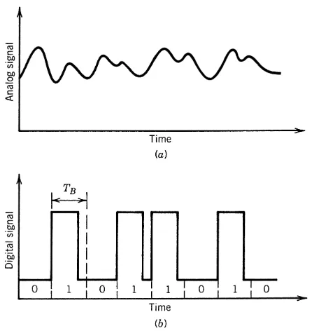
1.2.1 Analog and Digital Signals . . . 8
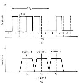
1.2.2 Channel Multiplexing . . . 11
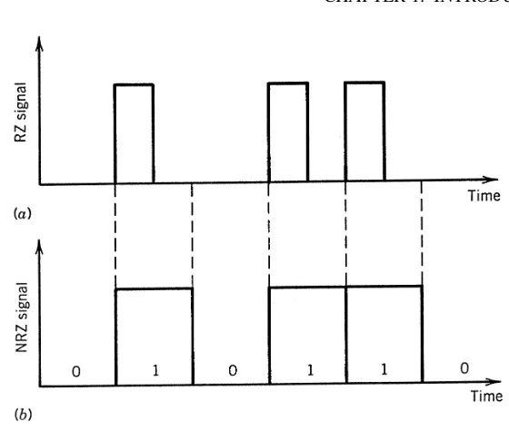
1.2.3 Modulation Formats . . . 13
1.3 Optical Communication Systems . . . 15
1.4 Lightwave System Components . . . 16
1.4.1 Optical Fibers as a Communication Channel . . . 17
1.4.2 Optical Transmitters . . . 17
1.4.3 Optical Receivers . . . 18
Problems . . . 19
References . . . 20
2 Optical Fibers 23 2.1 Geometrical-Optics Description . . . 23
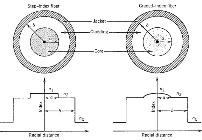
2.1.1 Step-Index Fibers . . . 24
2.1.2 Graded-Index Fibers . . . 26
2.2 Wave Propagation . . . 28
2.2.1 Maxwell’s Equations . . . 29
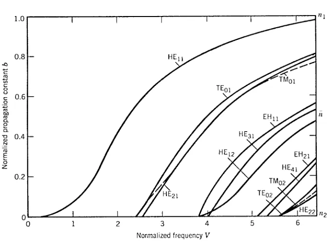
2.2.2 Fiber Modes . . . 31
2.2.3 Single-Mode Fibers . . . 34
2.3 Dispersion in Single-Mode Fibers . . . 37
2.3.1 Group-Velocity Dispersion . . . 38
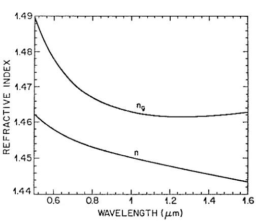
2.3.2 Material Dispersion . . . 39
2.3.3 Waveguide Dispersion . . . 41
2.3.4 Higher-Order Dispersion . . . 42
2.3.5 Polarization-Mode Dispersion . . . 43
2.4 Dispersion-Induced Limitations . . . 45
2.4.1 Basic Propagation Equation . . . 46
viii CONTENTS
2.4.2 Chirped Gaussian Pulses . . . 47
2.4.3 Limitations on the Bit Rate . . . 50
2.4.4 Fiber Bandwidth . . . 53
2.5 Fiber Losses . . . 55
2.5.1 Attenuation Coefficient . . . 55
2.5.2 Material Absorption . . . 56
2.5.3 Rayleigh Scattering . . . 57
2.5.4 Waveguide Imperfections . . . 58
2.6 Nonlinear Optical Effects . . . 59
2.6.1 Stimulated Light Scattering . . . 59
2.6.2 Nonlinear Phase Modulation . . . 64
2.6.3 Four-Wave Mixing . . . 66
2.7 Fiber Manufacturing . . . 67
2.7.1 Design Issues . . . 67
2.7.2 Fabrication Methods . . . 68
2.7.3 Cables and Connectors . . . 70
Problems . . . 72
References . . . 74
3 Optical Transmitters 77 3.1 Basic Concepts . . . 77
3.1.1 Emission and Absorption Rates . . . 78
3.1.2 p–nJunctions . . . 81
3.1.3 Nonradiative Recombination . . . 83
3.1.4 Semiconductor Materials . . . 84
3.2 Light-Emitting Diodes . . . 87
3.2.1 Power–Current Characteristics . . . 87
3.2.2 LED Spectrum . . . 89
3.2.3 Modulation Response . . . 90
3.2.4 LED Structures . . . 91
3.3 Semiconductor Lasers . . . 92
3.3.1 Optical Gain . . . 93
3.3.2 Feedback and Laser Threshold . . . 94
3.3.3 Laser Structures . . . 96
3.4 Control of Longitudinal Modes . . . 99
3.4.1 Distributed Feedback Lasers . . . 100
3.4.2 Coupled-Cavity Semiconductor Lasers . . . 102
3.4.3 Tunable Semiconductor Lasers . . . 103
3.4.4 Vertical-Cavity Surface-Emitting Lasers . . . 105
3.5 Laser Characteristics . . . 106
3.5.1 CW Characteristics . . . 107
3.5.2 Small-Signal Modulation . . . 110
3.5.3 Large-Signal Modulation . . . 112
3.5.4 Relative Intensity Noise . . . 114
3.5.5 Spectral Linewidth . . . 116
3.6.1 Source–Fiber Coupling . . . 118
3.6.2 Driving Circuitry . . . 121
3.6.3 Optical Modulators . . . 122
3.6.4 Optoelectronic Integration . . . 123
3.6.5 Reliability and Packaging . . . 124
Problems . . . 126
References . . . 127
4 Optical Receivers 133 4.1 Basic Concepts . . . 133
4.1.1 Detector Responsivity . . . 133
4.1.2 Rise Time and Bandwidth . . . 135
4.2 Common Photodetectors . . . 136
4.2.1 p–nPhotodiodes . . . 137
4.2.2 p–i–nPhotodiodes . . . 138
4.2.3 Avalanche Photodiodes . . . 142
4.2.4 MSM Photodetectors . . . 148
4.3 Receiver Design . . . 149
4.3.1 Front End . . . 149
4.3.2 Linear Channel . . . 150
4.3.3 Decision Circuit . . . 152
4.3.4 Integrated Receivers . . . 153
4.4 Receiver Noise . . . 155
4.4.1 Noise Mechanisms . . . 156
4.4.2 p–i–nReceivers . . . 158
4.4.3 APD Receivers . . . 159
4.5 Receiver Sensitivity . . . 162
4.5.1 Bit-Error Rate . . . 162
4.5.2 Minimum Received Power . . . 164
4.5.3 Quantum Limit of Photodetection . . . 167
4.6 Sensitivity Degradation . . . 168
4.6.1 Extinction Ratio . . . 168
4.6.2 Intensity Noise . . . 169
4.6.3 Timing Jitter . . . 171
4.7 Receiver Performance . . . 174
Problems . . . 176
References . . . 178
5 Lightwave Systems 183 5.1 System Architectures . . . 183
5.1.1 Point-to-Point Links . . . 183
5.1.2 Distribution Networks . . . 185
5.1.3 Local-Area Networks . . . 186
5.2 Design Guidelines . . . 188
5.2.1 Loss-Limited Lightwave Systems . . . 189
x CONTENTS
5.2.3 Power Budget . . . 192
5.2.4 Rise-Time Budget . . . 193
5.3 Long-Haul Systems . . . 195
5.3.1 Performance-Limiting Factors . . . 196
5.3.2 Terrestrial Lightwave Systems . . . 198
5.3.3 Undersea Lightwave Systems . . . 200
5.4 Sources of Power Penalty . . . 202
5.4.1 Modal Noise . . . 202
5.4.2 Dispersive Pulse Broadening . . . 204
5.4.3 Mode-Partition Noise . . . 205
5.4.4 Frequency Chirping . . . 209
5.4.5 Reflection Feedback and Noise . . . 213
5.5 Computer-Aided Design . . . 217
Problems . . . 219
References . . . 220
6 Optical Amplifiers 226 6.1 Basic Concepts . . . 226
6.1.1 Gain Spectrum and Bandwidth . . . 227
6.1.2 Gain Saturation . . . 229
6.1.3 Amplifier Noise . . . 230
6.1.4 Amplifier Applications . . . 231
6.2 Semiconductor Optical Amplifiers . . . 232
6.2.1 Amplifier Design . . . 232
6.2.2 Amplifier Characteristics . . . 234
6.2.3 Pulse Amplification . . . 237
6.2.4 System Applications . . . 241
6.3 Raman Amplifiers . . . 243
6.3.1 Raman Gain and Bandwidth . . . 243
6.3.2 Amplifier Characteristics . . . 244
6.3.3 Amplifier Performance . . . 246
6.4 Erbium-Doped Fiber Amplifiers . . . 250
6.4.1 Pumping Requirements . . . 251
6.4.2 Gain Spectrum . . . 252
6.4.3 Simple Theory . . . 253
6.4.4 Amplifier Noise . . . 255
6.4.5 Multichannel Amplification . . . 257
6.4.6 Distributed-Gain Amplifiers . . . 260
6.5 System Applications . . . 261
6.5.1 Optical Preamplification . . . 261
6.5.2 Noise Accumulation in Long-Haul Systems . . . 264
6.5.3 ASE-Induced Timing Jitter . . . 266
6.5.4 Accumulated Dispersive and Nonlinear Effects . . . 269
6.5.5 WDM-Related Impairments . . . 271
Problems . . . 272
7 Dispersion Management 279
7.1 Need for Dispersion Management . . . 279
7.2 Precompensation Schemes . . . 281
7.2.1 Prechirp Technique . . . 281
7.2.2 Novel Coding Techniques . . . 283
7.2.3 Nonlinear Prechirp Techniques . . . 285
7.3 Postcompensation Techniques . . . 286
7.4 Dispersion-Compensating Fibers . . . 288
7.5 Optical Filters . . . 290
7.6 Fiber Bragg Gratings . . . 293
7.6.1 Uniform-Period Gratings . . . 293
7.6.2 Chirped Fiber Gratings . . . 296
7.6.3 Chirped Mode Couplers . . . 299
7.7 Optical Phase Conjugation . . . 300
7.7.1 Principle of Operation . . . 300
7.7.2 Compensation of Self-Phase Modulation . . . 301
7.7.3 Phase-Conjugated Signal . . . 302
7.8 Long-Haul Lightwave Systems . . . 305
7.8.1 Periodic Dispersion Maps . . . 305
7.8.2 Simple Theory . . . 307
7.8.3 Intrachannel Nonlinear Effects . . . 309
7.9 High-Capacity Systems . . . 310
7.9.1 Broadband Dispersion Compensation . . . 311
7.9.2 Tunable Dispersion Compensation . . . 313
7.9.3 Higher-Order Dispersion Management . . . 315
7.9.4 PMD Compensation . . . 317
Problems . . . 321
References . . . 322
8 Multichannel Systems 330 8.1 WDM Lightwave Systems . . . 330
8.1.1 High-Capacity Point-to-Point Links . . . 331
8.1.2 Wide-Area and Metro-Area Networks . . . 334
8.1.3 Multiple-Access WDM Networks . . . 336
8.2 WDM Components . . . 339
8.2.1 Tunable Optical Filters . . . 339
8.2.2 Multiplexers and Demultiplexers . . . 344
8.2.3 Add–Drop Multiplexers . . . 348
8.2.4 Star Couplers . . . 350
8.2.5 Wavelength Routers . . . 351
8.2.6 Optical Cross-Connects . . . 354
8.2.7 Wavelength Converters . . . 357
8.2.8 WDM Transmitters and Receivers . . . 360
8.3 System Performance Issues . . . 362
8.3.1 Heterowavelength Linear Crosstalk . . . 363
xii CONTENTS
8.3.3 Nonlinear Raman Crosstalk . . . 366
8.3.4 Stimulated Brillouin Scattering . . . 369
8.3.5 Cross-Phase Modulation . . . 370
8.3.6 Four-Wave Mixing . . . 372
8.3.7 Other Design Issues . . . 374
8.4 Time-Division Multiplexing . . . 375
8.4.1 Channel Multiplexing . . . 375
8.4.2 Channel Demultiplexing . . . 377
8.4.3 System Performance . . . 380
8.5 Subcarrier Multiplexing . . . 381
8.5.1 Analog SCM Systems . . . 382
8.5.2 Digital SCM Systems . . . 385
8.5.3 Multiwavelength SCM Systems . . . 386
8.6 Code-Division Multiplexing . . . 388
8.6.1 Direct-Sequence Encoding . . . 388
8.6.2 Spectral Encoding . . . 390
Problems . . . 393
References . . . 394
9 Soliton Systems 404 9.1 Fiber Solitons . . . 404
9.1.1 Nonlinear Schr¨odinger Equation . . . 405
9.1.2 Bright Solitons . . . 406
9.1.3 Dark Solitons . . . 409
9.2 Soliton-Based Communications . . . 411
9.2.1 Information Transmission with Solitons . . . 411
9.2.2 Soliton Interaction . . . 412
9.2.3 Frequency Chirp . . . 414
9.2.4 Soliton Transmitters . . . 416
9.3 Loss-Managed Solitons . . . 418
9.3.1 Loss-Induced Soliton Broadening . . . 418
9.3.2 Lumped Amplification . . . 420
9.3.3 Distributed Amplification . . . 422
9.3.4 Experimental Progress . . . 425
9.4 Dispersion-Managed Solitons . . . 427
9.4.1 Dispersion-Decreasing Fibers . . . 427
9.4.2 Periodic Dispersion Maps . . . 429
9.4.3 Design Issues . . . 432
9.5 Impact of Amplifier Noise . . . 435
9.5.1 Moment Method . . . 435
9.5.2 Energy and Frequency Fluctuations . . . 437
9.5.3 Timing Jitter . . . 439
9.5.4 Control of Timing Jitter . . . 442
9.6 High-Speed Soliton Systems . . . 445
9.6.1 System Design Issues . . . 445
9.6.3 Impact of Higher-Order Effects . . . 450
9.6.4 Timing Jitter . . . 452
9.7 WDM Soliton Systems . . . 458
9.7.1 Interchannel Collisions . . . 458
9.7.2 Effect of Lumped Amplification . . . 461
9.7.3 Timing Jitter . . . 461
9.7.4 Dispersion Management . . . 463
Problems . . . 468
References . . . 469
10 Coherent Lightwave Systems 478 10.1 Basic Concepts . . . 479
10.1.1 Local Oscillator . . . 479
10.1.2 Homodyne Detection . . . 480
10.1.3 Heterodyne Detection . . . 480
10.1.4 Signal-to-Noise Ratio . . . 481
10.2 Modulation Formats . . . 482
10.2.1 ASK Format . . . 483
10.2.2 PSK Format . . . 484
10.2.3 FSK Format . . . 485
10.3 Demodulation Schemes . . . 487
10.3.1 Heterodyne Synchronous Demodulation . . . 488
10.3.2 Heterodyne Asynchronous Demodulation . . . 488
10.4 Bit-Error Rate . . . 490
10.4.1 Synchronous ASK Receivers . . . 490
10.4.2 Synchronous PSK Receivers . . . 492
10.4.3 Synchronous FSK Receivers . . . 493
10.4.4 Asynchronous ASK Receivers . . . 493
10.4.5 Asynchronous FSK Receivers . . . 495
10.4.6 Asynchronous DPSK Receivers . . . 497
10.5 Sensitivity Degradation . . . 497
10.5.1 Phase Noise . . . 498
10.5.2 Intensity Noise . . . 500
10.5.3 Polarization Mismatch . . . 502
10.5.4 Fiber Dispersion . . . 504
10.5.5 Other Limiting Factors . . . 506
10.6 System Performance . . . 507
10.6.1 Asynchronous Heterodyne Systems . . . 507
10.6.2 Synchronous Heterodyne Systems . . . 508
10.6.3 Homodyne Systems . . . 508
10.6.4 Current Status . . . 510
Problems . . . 511
References . . . 512
xiv CONTENTS
B Acronyms 520
C General Formula for Pulse Broadening 524
D Ultimate System Capacity 527
References . . . 528
Preface
Since the publication of the first edition of this book in 1992, the state of the art of fiber-optic communication systems has advanced dramatically despite the relatively short period of only 10 years between the first and third editions. For example, the highest capacity of commercial fiber-optic links available in 1992 was only 2.5 Gb/s. A mere 4 years later, the wavelength-division-multiplexed (WDM) systems with the total capacity of 40 Gb/s became available commercially. By 2001, the capacity of commercial WDM systems exceeded 1.6 Tb/s, and the prospect of lightwave systems operating at 3.2 Tb/s or more were in sight. During the last 2 years, the capacity of transoceanic lightwave systems installed worldwide has exploded. Moreover, sev-eral other undersea networks were in the construction phase in December 2001. A global network covering 250,000 km with a capacity of 2.56 Tb/s (64 WDM channels at 10 Gb/s over 4 fiber pairs) is scheduled to be operational in 2002. Several conference papers presented in 2001 have demonstrated that lightwave systems operating at a bit rate of more than 10 Tb/s are within reach. Just a few years ago it was unimaginable that lightwave systems would approach the capacity of even 1 Tb/s by 2001.
The second edition of this book appeared in 1997. It has been well received by the scientific community involved with lightwave technology. Because of the rapid ad-vances that have occurred over the last 5 years, the publisher and I deemed it necessary to bring out the third edition if the book were to continue to provide a comprehensive and up-to-date account of fiber-optic communication systems. The result is in your hands. The primary objective of the book remains the same. Specifically, it should be able to serve both as a textbook and a reference monograph. For this reason, the em-phasis is on the physical understanding, but the engineering aspects are also discussed throughout the text.
Because of the large amount of material that needed to be added to provide com-prehensive coverage, the book size has increased considerably compared with the first edition. Although all chapters have been updated, the major changes have occurred in Chapters 6–9. I have taken this opportunity to rearrange the material such that it is bet-ter suited for a two-semesbet-ter course on optical communications. Chapbet-ters 1–5 provide the basic foundation while Chapters 6–10 cover the issues related to the design of ad-vanced lightwave systems. More specifically, after the introduction of the elementary concepts in Chapter 1, Chapters 2–4 are devoted to the three primary components of a fiber-optic communications—optical fibers, optical transmitters, and optical receivers. Chapter 5 then focuses on the system design issues. Chapters 6 and 7 are devoted to the advanced techniques used for the management of fiber losses and chromatic
xvi PREFACE
persion, respectively. Chapter 8 focuses on the use of wavelength- and time-division multiplexing techniques for optical networks. Code-division multiplexing is also a part of this chapter. The use of optical solitons for fiber-optic systems is discussed in Chap-ter 9. Coherent lightwave systems are now covered in the last chapChap-ter. More than 30% of the material in Chapter 6–9 is new because of the rapid development of the WDM technology over the last 5 years. The contents of the book reflect the state of the art of lightwave transmission systems in 2001.
The primary role of this book is as a graduate-level textbook in the field ofoptical communications. An attempt is made to include as much recent material as possible so that students are exposed to the recent advances in this exciting field. The book can also serve as a reference text for researchers already engaged in or wishing to enter the field of optical fiber communications. The reference list at the end of each chapter is more elaborate than what is common for a typical textbook. The listing of recent research papers should be useful for researchers using this book as a reference. At the same time, students can benefit from it if they are assigned problems requiring reading of the original research papers. A set of problems is included at the end of each chapter to help both the teacher and the student. Although written primarily for graduate students, the book can also be used for an undergraduate course at the senior level with an appropriate selection of topics. Parts of the book can be used for several other related courses. For example, Chapter 2 can be used for a course on optical waveguides, and Chapter 3 can be useful for a course on optoelectronics.
Many universities in the United States and elsewhere offer a course on optical com-munications as a part of their curriculum in electrical engineering, physics, or optics. I have taught such a course since 1989 to the graduate students of the Institute of Optics, and this book indeed grew out of my lecture notes. I am aware that it is used as a text-book by many instructors worldwide—a fact that gives me immense satisfaction. I am acutely aware of a problem that is a side effect of an enlarged revised edition. How can a teacher fit all this material in a one-semester course onoptical communications? I have to struggle with the same question. In fact, it is impossible to cover the entire book in one semester. The best solution is to offer a two-semester course covering Chapters 1 through 5 during the first semester, leaving the remainder for the second semester. However, not many universities may have the luxury of offering a two-semester course on optical communications. The book can be used for a one-semester course provided that the instructor makes a selection of topics. For example, Chapter 3 can be skipped if the students have taken a laser course previously. If only parts of Chapters 6 through 10 are covered to provide students a glimpse of the recent advances, the material can fit in a single one-semester course offered either at the senior level for undergraduates or to graduate students.
This edition of the book features a compact disk (CD) on the back cover provided by the Optiwave Corporation. The CD contains a state-of-the art software package suitable for designing modern lightwave systems. It also contains additional problems for each chapter that can be solved by using the software package. Appendix E provides more details about the software and the problems. It is my hope that the CD will help to train the students and will prepare them better for an industrial job.
students who took my course on optical communication systems and helped improve my class notes through their questions and comments. Thanks are due to many instruc-tors who not only have adopted this book as a textbook for their courses but have also pointed out the misprints in previous editions, and thus have helped me in improving the book. I am grateful to my colleagues at the Institute of Optics for numerous dis-cussions and for providing a cordial and productive atmosphere. I appreciated the help of Karen Rolfe, who typed the first edition of this book and made numerous revisions with a smile. Last, but not least, I thank my wife, Anne, and my daughters, Sipra, Caroline, and Claire, for understanding why I needed to spend many weekends on the book instead of spending time with them.
Govind P. Agrawal
Index
absorption coefficient, 134 absorption rate, 80 accelerated aging, 124 acoustic frequency, 370 acoustic jitter,seetiming jitter acoustic waves, 59, 343, 454, 486 activation energy, 125
amplification factor, 227, 234, 238, 245, 270 amplified spontaneous emission, 252, 256,
264, 435 amplifier noise,seenoise
amplifier spacing, 265, 420, 421, 426 amplifiers
applications of, 231 bandwidth of, 227 C-band, 259 cascaded, 264–272
doped-fiber,seefiber amplifiers gain of, 227
in-line, 195, 241, 264–272, 280, 435 L-band, 259, 272
noise in, 230
parametric, 249, 305, 457 power, 231, 263
properties of, 226–231 Raman, 243–250, 259 S-band, 259
saturation characteristics of, 229 semiconductor,seesemiconductor
op-tical amplifiers
amplitude-phase coupling, 110, 117 amplitude-shift keying,seemodulation
for-mat
anticorrelation, 116, 205
antireflection coating, 92, 103, 233, 344 APD, 142–148
physical mechanism behind, 142 bandwidth of, 144
design of, 143
enhanced shot noise in, 159
excess noise factor for, 159 gain of, 144
optimum gain for, 161, 166 reach-through, 145 responsivity of, 144 SAGCM, 146 SAGM, 146 SAM, 145 staircase, 146 superlattice, 147 apodization technique, 294 ASCII code, 9
ATM protocol, 334, 336, 381 attenuation coefficient, 55 Auger recombination, 83, 84, 109
autocorrelation function, 115, 116, 156, 157, 389, 391
avalanche breakdown, 144 avalanche photodiode,seeAPD
bandgap discontinuity, 82 bandwidth
amplifier, 227, 228, 257 APD, 144
Brillouin-gain, 370 fiber, 53, 194
filter, 151, 271, 341, 344 front-end, 149 gain, 227 grating, 296 LED, 91 modulator, 485 noise, 156 photodetector, 136 photodiode, 139 Raman-amplifier, 243 Raman-gain, 63 RC circuit, 194 receiver, 384
semiconductor laser, 112
signal, 11, 316, 381
small-signal modulation, 110 Banyan network, 337
beat length, 35 Beer’s law, 55 bending loss, 58 Bessel function, 31, 494 biconical taper, 346, 351 birefringence, 35, 43, 449, 503
degree of, 35 random, 44, 317
bit rate–distance product, 3, 26, 27, 43, 52, 185, 191, 204, 206, 271, 332, 380, 426, 441
bit slot, 8, 50, 151, 152, 204, 207, 287, 306, 372, 376, 380, 411, 439 bit-error rate, 19, 162–164, 208, 262, 364,
490–497 blackbody radiation, 79 Boltzmann constant, 78, 157 boundary condition
periodic, 309, 430
Bragg condition, 100, 296, 343, 345 Bragg diffraction, 100, 101, 343, 344 Bragg reflectivity, 140
Bragg scattering, 486
Bragg wavelength, 103, 247, 293, 296, 313, 343, 344, 391, 416
Brillouin amplifier,seeamplifiers Brillouin crosstalk,seecrosstalk Brillouin gain, 61
Brillouin scattering, 59, 201, 304, 506 spontaneous, 59
stimulated, 59, 250, 344, 369 Brillouin shift, 60, 61, 344, 369 Brillouin threshold, 369 broadband access, 338 broadcast star, 337, 350–351 broadening factor, 49, 204 bubble technology, 356 Burrus-type LED, 91 bus topology, 185 butt coupling, 119 Butterworth filter, 505
cable television, 185, 382 carrier diffusion, 98 carrier heating, 110
carrier lifetime, 84, 107, 109, 235, 379 carrier-sense multiple access, 187
carrier-to-noise ratio, 383 catastrophic degradation, 124 CATV industry, 382 CDMA systems, 388–392 channel spacing, 242, 332 characteristic temperature, 108 chemical etching, 102 chemical-vapor deposition
metal-organic, 86 modified, 69 plasma-activated, 69 chirp,seefrequency chirp
chirp parameter, 47, 52, 113, 211, 281, 283, 415
chirped mode coupler, 299 chromium heater, 292 circuit switching, 334, 336 clipping noise, 386
clock recovery, 152, 162, 171 clock signal, 377
CNR,seecarrier-to-noise ratio coaxial cable, 2, 187, 190, 381 code-division multiplexing
codes for, 388 coherent, 390 codes
bipolar, 390 orthogonal, 389, 391 pseudo-orthogonal, 391 unipolar, 390
coherence function, 50 coherence time, 392, 498 coherent detection, 479–481 coherent lightwave systems
advantages of, 479 bit-error rate for, 490–497
demodulation schemes for, 487–490 dispersion effects in, 504
field trials with, 510
heterodyne,seeheterodyne receiver homodyne, 508
intensity noise in, 500–502 long-haul, 508
modulation formats for, 482–487 performance of, 507–511 phase noise in, 498–500 polarization effects in, 502, 504 sensitivity degradation for, 497–507 collision length, 458–461
INDEX 533
color-center laser, 425 computer-aided design, 217
confinement factor, 37, 107, 235, 293 connector loss,seeloss
conversion efficiency, 304 core–cladding interface, 24, 26, 58 correlation length, 45
correlation technique, 389 Costas loop, 488
coupled-cavity mechanism, 103 coupled-mode equations, 293 coupling coefficient, 293 coupling efficiency, 88, 91, 118 critical angle, 24, 58, 87 cross-correlation coefficient, 206 cross-correlation function, 389 cross-gain saturation, 242, 257, 357 cross-phase modulation, 65, 272, 359, 445
demultiplexing with, 377 interchannel, 370–372, 508 intrachannel, 310
soliton interaction through, 459 crosstalk, 362–375
amplifier-induced, 242 Brillouin-induced, 369 EDFA-induced, 257 filter-induced, 363–365 FWM-induced, 67, 372–374 heterowavelength, 363 homowavelength, 363, 365 in-band, 365–366
linear, 363–366 nonlinear, 366–374 out-of-band, 363–365
Raman-induced, 63, 366–368, 387 Rayleigh, 248
router-induced, 365–366 SCM, 387
XPM-induced, 65, 370–372, 387 crosstalk penalty, 363, 365
CRZ format, 14, 267, 309 cutoff condition, 33 cutoff wavelength, 135
dark current, 136, 156, 482 deBruijn network, 337
decision circuit, 152, 162, 204, 207, 284, 288, 495
decision threshold, 162, 164, 287, 363 decoder, 389
delay line, 389 delay technique, 375
delay-demodulation scheme, 490 demodulation
asynchronous, 488 delay, 489
schemes for, 487–490 synchronous, 488 demultiplexer, 344–347 all-fiber, 346 concave-grating, 362 diffraction-based, 344 electro-optic, 377 filter-based, 345 grating-based, 344 interference-based, 344 TDM, 377–380
terahertz optical asymmetrical, 379 waveguide-grating, 347
density of states, 80, 86 depletion layer, 145
depletion width, 81, 137, 139 detector,seephotodetector diapersion
anomalous, 434 differential gain, 93
differential-detection technique, 392 diffusion coefficient, 81, 115 diffusion length, 81 digital hierarchy, 12
synchronous, 13
digital video transport systems, 388 dipole relaxation time, 227, 252 direct-sequence encoding, 389 directional coupler, 188, 346, 349, 355
grating-assisted, 349 dispersion, 37–45
anomalous, 197, 405 comb-like, 411, 418 fourth-order, 317 grating, 294, 296 grating-induced, 294
group-velocity, 38–42, 96, 194, 195, 271, 279, 404–411, 504 intermodal, 190, 194 material, 39–40 modal, 25 multipath, 25, 26
polarization-mode, 36, 43, 197, 449, 455
pulse broadening due to, 47–50, 288 residual, 313, 314
temperature-induced change in, 313 third-order, 42, 51, 280, 315, 317, 381,
424, 450, 457 tunable, 314
waveguide, 39, 41, 289 dispersion allocation, 434 dispersion compensation
broadband, 311–317 dynamic, 313
electronic techniques for, 286–288 long-haul, 305–310
polarization-mode, 317–320 third-order, 315
tunable, 313
dispersion equalization, 287 dispersion length, 48, 281, 414, 421 dispersion management, 269, 271, 380, 427–
435, 463–467 broadband, 311–320 DCF for, 288–289 dense, 432
duobinary technique for, 284 fiber gratings for, 293–299 filters for, 290–293 FSK format for, 283 higher-order, 315–317 long-haul, 305–310 need for, 279–281 periodic, 305–310, 374 phase conjugation for, 300–305 prechirping technique for, 281–283 WDM, 310–320
dispersion map, 309 optimum, 464 period of, 306
periodic, 305, 429–435, 464 strength of, 433
two-section, 308
dispersion parameter, 38, 46, 195, 280 dispersion penalty,seepower penalty dispersion relation, 60
dispersion slope, 42, 51, 312, 316, 381 relative, 312
dispersion trimming, 313
dispersion-compensating fiber,seefibers dispersion-decreasing fiber,seefibers
dispersion-induced limitations, 50–53, 279– 281
dispersion-shifted fibers,seefibers dispersion-supported transmission, 283 dispersive waves, 408, 415, 420, 422, 424,
445
distributed amplification, 248, 260, 422–425, 430
distributed Bragg reflector, 101 distributed feedback,seefeedback distributed feedback lasers, 100, 207, 418
fabrication of, 101
gain-coupled, 101, 360, 487 linewidth saturation in, 117 multisection, 103, 486, 499 phase-shifted, 101, 208 double-exposure technique, 297 double-heterostructure design, 82 driving circuitry, 121
duobinary code, 284, 298
EDFA
amplification characteristics of, 253 C-band, 258
cascaded chain of, 257, 264 distributed-gain, 260 gain spectrum of, 252 gain-clamped, 258 in-line, 264–272 L-band, 258
multichannel amplification in, 257 noise in, 255
parallel configuration for, 259 pumping of, 251
semiconductor lasers for, 251 soliton transmission with, 426 spectral nonuniformity of, 257 system applications of, 261–272 two-stage, 258
effective core area, 37, 61, 272, 309, 405 effective index, 345
effective mass, 80 Einstein’s coefficients, 79 elasto-optic coefficient, 61
electron–hole recombination, 81, 83, 114 electron-beam lithography, 102
INDEX 535
direct sequence, 388 spectral, 390
energy enhancement factor, 421, 434 energy-band diagram, 81
envelope detector, 489, 498 epitaxial growth, 86, 102 equalization technique, 287, 288 equalizing filter,seefilter
erbium-doped fiber amplifiers,seeEDFA error probability,seebit-error rate Ethernet, 187
Euler–Lagrange equation, 308 evanescent wave, 299 excess noise factor, 159 excited-state absorption, 253 extinction ratio, 168, 355 eye closure, 311, 363
eye diagram, 153, 176, 287, 311
Fabry–Perot cavity, 94, 140, 148, 417 Fabry–Perot interferometer, 214, 216, 232,
340 Faraday effect, 120 fast axis, 36 FDDI, 188
FDM,seemultiplexing, WDM systems feedback
cavity, 94 distributed, 100 electrical, 374 negative, 150
optical, 102, 120, 154, 213 reflection, 213, 384, 506 feedback resistor, 150 feedback-induced chaos, 214
feedback-induced RIN enhancement, 214 Fermi level, 79, 81
Fermi–Dirac distribution, 79 fiber amplifiers, 250
distributed-gain, 260 erbium-doped,seeEDFA system applications of, 261–272 fiber cables, 70
fiber coupler, 346, 351, 376 fiber dispersion,seedispersion fiber grating,seegrating, 411 fiber gratings
long-period, 258 fiber lasers
dual-frequency, 418
mode-locked, 362, 380, 417 fiber loss,seeloss
fiber modes, 31–37 classification of, 33 effective index of, 33 eigenvalue equation for, 32 field distribution of, 35 fundamental, 35 hybrid, 33
propagation constant of, 33 spot size of, 36
transverse-electric, 33 transverse-magnetic, 33
fiber nonlinearity,seenonlinear effects fiber-detector coupling, 154
fiber-loop mirror, 411
fiber-optic systems,seelightwave systems fibers
bandwidth of, 53 birefringence of, 35 chalcogenide, 58
depressed-cladding, 68, 289 design of, 67
dispersion-compensating, 288–289, 313, 315, 434
dispersion-decreasing, 42, 302, 411, 417, 427–429, 463
dispersion-flattened, 41, 466
dispersion-shifted, 41, 67, 68, 191, 199, 269, 312, 369, 372, 411, 457, 503
dry, 7, 332 dual-core, 299 elliptical-core, 289 fabrication of, 68 fluoride, 58, 259
geometrical-optics description of, 23 graded-index, 26–28, 190, 192, 195 loss of, 55–59
low-PMD, 45
modes of,seefiber modes multimode, 24–28, 190, 202 negative-slope, 312 nonlinear effects in, 59–67 nonzero-dispersion-shifted, 374 parabolic-index, 26
plastic, 28, 203
polarization-maintaining, 36, 44, 236, 448, 503
pulse propagation in, 46 reduced-slope, 43 reverse-dispersion, 43, 312 single-mode, 34–37
standard, 280, 288, 296, 312, 433, 435 tellurite, 259
two-mode, 289
wave propagation in, 28–33 field-effect transistor, 153
modulation-doped, 154 filter
acousto-optic, 258, 343 add–drop, 349 amplifier-based, 344
bandpass, 152, 307, 418, 442, 488, 489, 498
Butterworth, 505 equalizing, 290–293
Fabry–Perot, 291, 311, 339–342, 364, 442, 462
grating, 342 high-pass, 152 in-line, 442 interference, 258 low-pass, 151, 488, 505
Mach–Zehnder, 258, 292, 342, 346, 349
microwave, 286
optical, 270, 290–293, 416, 442 raised-cosine, 151, 210 reflection, 293
sliding-frequency, 442, 462, 465 surface-acoustic-wave, 152 transversal, 288
tunable optical, 339–344, 363 finesse, 341
flame hydrolysis, 69 flip-chip technique, 153, 154 fluorescence time, 227, 255 FM index, 486
forward-error correction, 199, 271, 333, 391 four-wave mixing, 66, 242, 272, 302, 359,
372–374, 445, 457, 463, 503, 507 efficiency of, 359, 373
intrachannel, 310 nondegenerate, 304 Franz–Keldysh effect, 122 free spectral range, 233, 311, 340 free-carrier absorption, 236
frequency chirp, 47, 52, 112, 191, 280, 406, 414, 431
amplifier-induced, 239, 285, 358 fiber-induced, 286
gain-switching-induced, 416 linear, 313
modulation-induced, 201 nonlinear, 314
power penalty due to, 209–213 SPM-induced, 405
XPM-induced, 371 frequency hopping, 390
frequency-division multiplexing,see multi-plexing, WDM systems frequency-shift keying,seemodulation
for-mat front end, 149
bandwidth of, 149 high-impedance, 149 low-impedance, 150 transimpedance, 150 gain amplifier, 228 APD, 144 Brillouin, 344 parametric, 249
polarization-dependent, 45, 197, 456 Raman, 243
gain bandwidth,seebandwidth gain coefficient, 93, 227 gain margin, 101, 208 gain nonuniformity, 375
gain saturation, 229, 234, 245, 257, 379 gain spectrum, 252
gain switching, 114, 416
gain–bandwidth product, 146, 147 gain-flattening technique, 249, 258, 375 Gaussian distribution, 36, 494
Gaussian pulse,seepulse
Gaussian random process, 114, 117, 162 Gaussian statistics, 156, 162, 173, 269, 456 ghost pulse, 310
Gordon–Haus jitter,seetiming jitter graded-index fiber,seefibers graded-index lens, 345 grating
acoustically induced, 343 apodized, 294, 298
INDEX 537
Bragg, 293, 313, 342, 345, 346, 349, 357, 372
built-in, 100, 289, 343, 344 cascaded, 311
chirped, 104, 296–299, 311, 385, 416 concave, 345
DFB-laser, 100 diffraction, 344 dispersion of, 296 elliptical, 345 external, 103
fiber, 247, 255, 293–299, 304, 342, 346, 372, 390, 391, 416 insertion loss of, 298 Moir´e, 298, 392
nonlinear-index, 197, 463 nonlinearly chirped, 314, 316 phase-shifted, 346
reflection, 345 sampled, 311, 316, 390 superstructure, 104 waveguide, 351
grating period, 100, 104, 289, 293, 313, 345
group index, 96
group velocity, 38, 266, 439, 444 group-velocity dispersion,seedispersion group-velocity mismatch, 272
GVD,seedispersion
GVD parameter, 38, 46, 271, 280, 288, 303, 404–411
Hermite–Gauss function, 430 heterodyne detection, 480 heterodyne receiver
ASK asynchronous, 493–495 ASK synchronous, 490–492 asynchronous, 488, 507 balanced, 501
dispersion compensation at, 286 DPSK asynchronous, 497 dual-filter FSK, 489, 493, 495 FSK asynchronous, 495–496 FSK synchronous, 493 integrated, 510
intensity noise at, 500–502 performance of, 507–511 phase noise in, 498–500 phase-diversity, 499
polarization-diversity, 504, 510
PSK synchronous, 492
sensitivity degradation of, 497–507 sensitivity of, 490–497
synchronous, 488, 508 high-definition television, 186 holographic technique, 102, 294, 297 homodyne detection, 287, 480 homodyne receiver
ASK synchronous, 491 PSK synchronous, 492 homogeneous broadening, 252 hypercube architecture, 337
impact ionization, 142, 159 impulse response, 53
index-matching liquid, 119, 214 inelastic scattering, 243 InGaAsP/InP technology, 356 inhomogeneous broadening, 252 injection locking, 113
integrated circuits
optoelectronic, 123, 153, 360, 510 photonic, 124
integrated-services digital network, 185 interaction length, 61
interdigited electrode, 148 interferometer
Fabry–Perot, 214, 291, 339 Gires–Tournois, 291
Mach–Zehnder, 292, 342, 349, 358, 392
Michelson, 343, 359, 374 Sagnac, 343, 359, 377
intermediate frequency, 286, 479, 488 intermodulation distortion, 383 intermodulation products, 383
International Telecommunication Union, 332 Internet, 187
Internet protocol, 381
intersymbol interference, 151, 204 intraband nonlinearity, 242 intrachannel nonlinear effects, 309 inverse scattering method, 405, 409, 414,
415
ionization coefficient ratio, 144, 161, 166 ISDN, 185
ITU wavelength grid, 332
Lagrangian density, 308 Lambertian source, 88, 92 Langevin force, 114 laser linewidth, 116, 498 laser threshold, 94 lattice constant, 82, 85, 86 LED, 87–92
bandwidth of, 91 broad-spectrum, 92 coupling efficiency for, 119 edge-emitting, 92
modulation response of, 90 P–I characteristics of, 87 reliability of, 125 resonant-cavity, 92 responsivity of, 89 spectral distribution of, 89 structures for, 91
surface-emitting, 91, 119 temperature dependence of, 89 transfer function of, 90 lens coupling, 119, 120 light-emitting diodes,seeLED lightwave systems
amplifiers for, 261–272 architectures for, 183
coherent,seecoherent systems components of, 16–19 design of, 188–195
dispersion-limited, 50–53, 190–192, 269, 279–281
evolution of, 4–8
high-capacity, 310–320, 331 history of, 1–4
long-haul, 195–202 loss-limited, 189–190 point-to-point, 183–185 quasi-linear, 309
soliton,seesoliton systems spectral efficiency of, 332 subcarrier,seeSCM systems submarine, 306
TDM,seeTDM systems terrestrial, 198–200, 306 undersea, 124, 200–202, 266 unguided, 15
WDM,seeWDM systems LiNbO3technology, 304, 355, 357 linear channel, 150
transfer function of, 151
linewidth enhancement factor, 110, 113, 117, 212, 237, 282, 416
liquid crystal, 341, 356 liquid-phase epitaxy, 86 load resistor, 150, 157 local oscillator, 479–482
intensity noise of, 500 linewidth of, 498
local-area network,seenetworks Lorentzian spectrum, 60, 117, 227 loss
bending, 58, 289 cavity, 95, 99, 107 channel, 192 connector, 72, 192 coupling, 243, 346, 359 distribution, 188
fiber, 55–59, 189, 301, 418 insertion, 186, 289, 298, 304, 356 internal, 95, 236, 341
mode-selective, 202
polarization-dependent, 45, 197, 456 scattering, 236
splice, 72, 192 loss management, 418–427 lumped amplification, 420–422, 461
Mach–Zehnder interferometer, 123, 342, 346, 377, 410
map period, 306, 372, 432 map strength, 433
critical, 433 Marcum’sQfunction, 495 Markoffian approximation, 114 matched-filter detection, 389 material absorption, 56
material dispersion,seedispersion Maxwell’s equations, 29
mean time to failure, 124 MEMS technology, 106, 355 meridional rays, 26
metropolitan-area network,seenetworks Michelson interferometer, 343, 359, 374 microlens, 345
micromirror, 355 microstrip line, 287
microwave communication, 2, 381, 478 microwave subcarrier, 382
INDEX 539
mode
fiber,seefiber modes
longitudinal, 96, 99, 202, 205, 416 waveguide, 345
mode converter, 289, 299 mode index, 33, 35, 297
carrier-induced change in, 110 periodic variation of, 100 mode locking, 114, 416
active, 416 harmonic, 417
mode-partition coefficient, 206
mode-partition noise, 116, 171, 205–208 mode-suppression ratio, 100, 101, 207, 215 modulation
amplitude, 14, 282 cross-phase, 65 frequency, 14, 283 large-signal, 112 nonlinear phase, 64 phase, 14, 110, 283, 418 pulse-code, 10
pulse-duration, 10 pulse-position, 10 self-phase, 64
sinusoidal, 90, 110, 418 small-signal, 110 synchronous, 310, 443 synchronous phase, 444 modulation bandwidth, 91, 92 modulation format, 13–15, 482–487
AM-VSB, 382, 384 ASK, 14, 483–484 carrier-less AM/PM, 385 continuous-phase FSK, 487 CPFSK, 510
CRZ, 14, 309 DPSK, 485
FSK, 14, 283, 385, 485–487 MSK, 487
nonreturn-to-zero,seeNRZ format NRZ, 13
on–off keying, 15, 483 PSK, 15, 484–485 quadrature AM, 385 quadrature PSK, 385 return-to-zero,seeRZ format RZ, 13
RZ-to-NRZ conversion, 362 modulation index, 383, 384
modulation instability, 197, 305 modulation response, 110 modulator
acousto-optic, 486 amplitude, 443
electroabsorption, 122, 123, 283, 358, 360, 417
external, 280 frequency, 370 integrated, 280 intensity, 426
LiNbO3, 123, 411, 417, 426, 443, 484 Mach–Zehnder, 123, 283, 377, 410,
418, 484
multiquantum-well, 123, 417 phase, 370, 390, 411, 444, 467, 484,
485 synchronous, 462 molecular-beam epitaxy, 86 moment method, 267
momentum matrix element, 80 MONET project, 335, 356 Morse code, 2
MPEG, 11, 186 multiplexer
add–drop, 348–350 TDM, 375
WDM,seedemultiplexer multiplexing code-division, 388–392 coherence, 392 electric-domain, 11 frequency-division, 11 polarization, 447–450 subcarrier, 381–388
time-division, 11, 315, 375–381 wavelength-division, 330–362 multiplication layer, 143
networks access, 336 active-star, 188 all-optical, 336 broadcast, 185, 334 CATV, 185, 381–386 distribution, 185, 334 local-area, 186, 334 local-loop, 336 mesh, 334
metropolitan-area, 185, 334 multihop, 335
passive-star, 188
WDM,seeWDM networks wide-area, 334
noise
amplifier, 197, 230, 255, 264, 435– 437
beat, 392 clipping, 385 current, 261
electrical amplifier, 157 Gaussian, 527
intensity, 115, 169, 214, 500–502 laser, 114–117
mode-partition, 116, 205–208 1/f, 117
phase, 216, 498–500 preamplifier, 261 receiver, 155–162, 482 shot, 114, 156, 262, 481
spontaneous-emission, 230, 261, 270 thermal, 157, 166, 262, 481
white, 156, 157, 230
noise figure, 157, 230, 231, 236, 241, 255, 263
nonlinear effects, 59–67, 196, 269, 301, 309, 404–411, 506
cascaded, 304 interchannel, 306, 310 intrachannel, 306, 309, 380 second-order, 304
nonlinear gain, 116, 117 nonlinear length, 270
nonlinear optical-loop mirror, 377, 445 nonlinear refraction, 64
nonlinear Schr¨odinger equation, 66, 196, 270, 307, 405–411, 450, 529
nonradiative recombination, 83
NRZ format, 13, 152, 194, 195, 282, 371, 376, 411, 418
numerical aperture, 25, 88, 92, 118 Nyquist criterion, 9
Nyquist noise, 157
on–off keying,seemodulation format optical amplifiers,seeamplifiers optical beat interference, 387 optical bus, 186
optical circulator, 291, 298, 304, 342, 357 optical communication systems,see
light-wave systems optical cross-connect, 354–357 optical data links, 184, 203 optical detector,seephotodetector optical feedback,seefeedback optical fibers,seefibers optical filter,seefilter
optical isolator, 120, 213, 216, 506 optical networks,seenetworks optical phonons, 243
optical preamplifier,seepreamplifier optical receiver
APD, 159 components of, 18 design of, 149 front end of, 149 integrated, 153, 510 linear channel of, 150 noise in, 155–162 OEIC, 153 p–i–n, 158 packaging of, 154 performance of, 174–176 role of, 18
sensitivity of, 162–168 WDM, 360
optical switch,seeswitch optical tap, 185
optical transmitter, 118–126 components of, 17 driving circuitry in, 121 monolithic, 123 OEIC, 123
INDEX 541
source–fiber coupling in, 118 WDM, 360
optoelectronic integration for receivers, 153 for transmitters, 123 optogalvanic effect, 374 orthoconjugate mirror, 304 outside-vapor deposition, 69
p–i–nphotodiode, 138 p–njunction, 81, 137 p–nphotodiode, 137
packet switching, 334, 336, 381 parametric amplifier, 249 paraxial approximation, 27 partial soliton communication, 434 passive photonic loop, 338 periodic poling, 304 perturbation theory, 444
phase conjugation, 67, 300–305, 316, 359, 457, 503
phase modulation, 317, 370
phase-locked loop, 374, 487, 488, 498 phase-mask technique, 297
phase-matching condition, 66, 302, 343, 463 phase-shift keying,seemodulation format photodetector
avalanche,seeAPD bandwidth of, 136 design of, 136 inverted MSM, 148 MSM, 148
quantum efficiency of, 134 responsivity of, 134 traveling-wave, 141 photodiode
p–i–n, 138 p–n, 137 waveguide, 141 photoelastic effect, 343 photon lifetime, 107 photoresist, 102
piezoelectric transducer, 313 pigtail, 118, 416
planar lightwave circuit, 155, 292, 316, 342, 343, 346, 353, 355, 376 Planck’s formula, 79
PMD,seedispersion
compensation of, 197, 317–320 first-order, 45
pulse broadening induced by, 45 second-order, 45
PMD parameter, 45, 449, 455 point-to-point links, 183–185
WDM, 331–334 Poisson statistics, 156, 167 polarization multiplexing, 272, 445 polarization scrambling, 271, 333, 467, 503 polarization-mismatch effects, 502
polarization-mode dispersion,seedispersion polarization-multilevel coding, 450 population inversion, 79–81, 93, 256 population-inversion factor, 230 postcompensation technique, 313 power booster, 231, 263
power budget, 192–193, 384 power penalty
chirp-induced, 210
dispersion-induced, 204, 504 extinction ratio, 169 feedback-induced, 215 filter-induced, 363 FWM-induced, 372 heterodyne-detection, 481 intensity-noise, 170 LO-noise, 500 modal-noise, 202
mode-partition noise, 206–208 phase-noise, 498
Raman-induced, 368 Rayleigh-induced, 248 RIN-induced, 170, 500 router-induced, 365 sources of, 202–217 timing-jitter, 173 XPM-induced, 372
preamplifier, 149, 151, 241, 261–264 prechirp technique, 281–283 preform, 68, 70
principal states of polarization, 317 pulse
chirped, 47, 211, 267, 281, 307, 414 gain-switched, 416
Gaussian, 47, 204, 211, 239, 267, 281, 286, 307, 408, 429
mode-locked, 416
secant hyperbolic, 407, 429 super-Gaussian, 52, 238, 282 ultrashort, 237, 362
general formula for, 524 GVD-induced, 48 PMD-induced, 44, 45 source-induced, 50
pulse-code modulation,seemodulation pump depletion, 245
pump-station spacing, 260, 423 pumping efficiency, 251 pumping scheme
backward, 248, 423 bidirectional, 423
Q parameter, 164, 165, 168, 170, 172, 262, 270, 491
quantization noise, 9 quantum efficiency
differential, 109 external, 87, 109, 148 internal, 83, 87, 109 photodetector, 134 total, 88, 109 quantum limit, 167, 174
quantum-well laser,seesemiconductor lasers quasi-phase-matching, 304
Raman amplification, 245, 367, 422, 425 backward, 423
Raman amplifier,seeamplifiers Raman crosstalk,seecrosstalk Raman gain, 63, 243, 366
Raman scattering, 59, 366–368, 506 intrapulse, 424, 450
spontaneous, 62, 246 stimulated, 62, 243, 445 Raman shift, 62
Raman-induced frequency shift, 424, 450 Raman-induced jitter,seetiming jitter rare-earth elements, 250
rate equation, 90, 107, 114, 253 Rayleigh distribution, 494 Rayleigh scattering, 57, 248, 249 RC circuit, 193
RC time constant, 136, 137 receiver,seeoptical receiver receiver design,seeoptical receiver receiver noise,seenoise
receiver sensitivity, 162–168, 241, 261, 263, 490–497, 507
degradation of, 168–173, 202–217, 497– 507
recirculating fiber loop, 197, 269, 307, 309, 426, 435, 464
recombination rate, 84 recombination time, 84 regenerators, 184, 196, 280, 357 relative intensity noise,seeRIN
relaxation oscillations, 111, 112, 115, 117, 210
repeater spacing, 185, 419 repeaters, 184
resonant coupler, 349 responsivity, 261
APD, 144, 159 LED, 89
photodetector, 134 Rice distribution, 494, 496 ridge waveguide, 98, 361 RIN, 115, 170, 214, 384, 500
dispersion-induced, 385 reflection-induced, 384 spectrum of, 115 ring cavity, 417 ring topology, 188
rise time, 112, 135, 193–195 rise-time budget, 193–195 router
passive, 352 static, 352
waveguide-grating, 351 WDM, 351
RZ format, 13, 114, 152, 194, 195, 317, 372, 376, 411, 418
Sagnac interferometer, 343, 359, 377 sampling theorem, 9
saturable absorber, 417, 445 saturation current, 81 saturation energy, 237, 255 saturation power, 227, 235
output, 229, 235, 241, 255 saturation velocity, 137 SBS,seeBrillouin scattering Schottky barrier, 148 SCM systems, 381–388
INDEX 543
self-phase modulation, 64, 196, 239, 270, 286, 301–302, 307, 386, 404– 411, 506
Sellmeier equation, 39 semiconductor lasers
broad-area, 97
buried heterostructure, 98 characteristics of, 106 coupled-cavity, 102 coupling efficiency for, 120 DFB,seedistributed feedback lasers EDFA pumping by, 251
external-cavity, 416
feedback sensitivity of, 120, 214 FM response of, 486
frequency stability of, 374 gain in, 93
gain-guided, 97 index-guided, 98 intensity noise of, 500 linewidth of, 116 longitudinal modes of, 96 materials for, 84
mode-locked, 240, 416
modulation response of, 110–114 MQW, 87, 213
multisection, 344 narrow linewidth, 499 noise in, 114–117 P–ICharacteristics, 109 packaging of, 125 quantum-dot, 87 quantum-well, 87 quantum-wire, 87 reliability of, 124 single-frequency, 99 SNR of, 116
strained MQW, 87, 213, 499 stripe-geometry, 97 structures for, 96–99 surface-emitting, 105 temperature sensitivity of, 107 threshold of, 94
transfer function of, 111 tunable, 103, 359
semiconductor optical amplifiers, 232–243 angled-facet, 233
applications of, 241 bandwidth of, 233 buried-facet, 234
demultiplexing with, 379 design of, 233
Fabry–Perot, 232 facet reflectivity of, 233 filters based on, 344
four-wave mixing in, 304, 359 mode locking with, 417 polarization sensitivity of, 236 properties of, 234–243 pulse amplification in, 237 switching with, 356 tilted-stripe, 233 traveling-wave, 232
wavelength conversion with, 357 window-facet, 234
shot noise,seenoise shuffle network, 337 sideband instability, 197 signal
analog, 8–11, 382–385 audio, 8, 11, 185 beat, 418 binary, 8 clock, 377 crosstalk, 365 digital, 8–11, 385–386 duobinary, 284 FSK, 284 heterodyne, 481 homodyne, 480 microwave, 286, 381 multichannel, 340 phase-conjugated, 302 reduced-bandwidth, 284 spectrally encoded, 390 studio-quality video, 385 TE-polarized, 236 time-reversed, 301 TM-polarized, 236 video, 8, 11, 185, 382
WDM, 257, 345, 348, 351, 353, 368 signal-to-noise ratio, 10, 116, 158–161, 230,
372, 481 signature sequence, 389
silica-on-silicon technology, 342, 347, 349, 351, 353, 361, 376
silicon optical bench, 120, 342 silicon-on-insulator technology, 351 skew rays, 26
slow axis, 36
small-signal gain, 235, 245 SNR,seesignal-to-noise ratio Soleil–Babinet compensator, 319 soliton period, 406
soliton self-frequency shift, 450 soliton systems
amplifier noise in, 435–437 amplifier spacing for, 420–422 design of, 425–445
dispersion management for, 427–435, 463–467
high-capacity, 445–450 jitter control in, 442–445 modulation format for, 411 timing jitter in, 439–445 transmitters for, 416–418 WDM, 458–467 solitons
amplification of, 427 black, 409
bright, 406 broadening of, 418 collision of, 458–462, 464 dark, 409–411
DDF for, 427–429
dispersion-managed, 309, 429–435 distributed amplification of, 422 effect of fiber loss, 418 fundamental, 406 Gaussian shape for, 429 gray, 409
guiding-center, 421 higher-order, 406
information transmission with, 411 interaction of, 412–414, 447, 456 loss-managed, 418–427
order of, 406
orthogonally polarized, 465 path-averaged, 421
periodic amplification of, 420–422 properties of, 406–408
self-frequency shift of, 424 sources of, 416–418 SONET, 13, 199
source–fiber coupling, 118 spatial hole burning, 110 spatial phase filter, 316 speckle pattern, 202 spectral broadening, 280
spectral efficiency, 332, 341, 392 spectral filtering, 411
spectral hole burning, 110, 252 spectral inversion, 457
midspan, 300
spectral slicing, 338, 361, 362 splice loss,seeloss
split-step Fourier method, 270, 429 spontaneous emission, 78, 79, 89, 107, 114,
230, 261
spontaneous-emission factor, 107, 230, 236, 255
spot size, 36
spot-size converter, 120, 485 spread-spectrum technique, 388 squaring loop, 488
SRS,seeRaman scattering staircase approximation, 428, 463 star coupler, 188, 337, 338, 350–351, 381 star topology, 188
Stark effect, 417
quantum-confinement, 485 Stark splitting, 252
stimulated Brillouin scattering,seeBrillouin scattering
stimulated emission, 78, 80, 92, 107 stimulated Raman scattering,seeRaman
scat-tering Stokes shift, 59, 250
stop band, 293, 294, 299, 311, 314, 346 streak camera, 286
subcarrier multiplexing, see multiplexing, SCM systems
INDEX 545
thermo-optic, 355 wavelength-division, 357 switching time, 355
synchronous digital hierarchy,seeSDH synchronous optical network,seeSONET synchronous transport module, 13 system design,seelightwave systems system margin, 192, 217
TCP/IP protocol, 381 TDM,seemultiplexing TDM systems, 375–381
demultiplexer for, 377–380 multihop, 381
multiplexer for, 375 performance of, 380 single-hop, 381 TE polarization, 236
telecommunication fiber links, 198–202 telegraphy, 2
thermal equilibrium, 78, 79, 81 thermal noise,seenoise thermo-optic coefficient, 355 thermoelectric cooler, 122, 125 thermoelectric heater, 416
segmented, 314
third-order dispersion,seedispersion three-level system, 253
threshold condition, 95 threshold current, 95, 98, 108
temperature dependence of, 107 time-division multiplexing, see
multiplex-ing, TDM systems
timing jitter, 372, 439–445, 452–457, 464 acoustic, 454
ASE-induced, 266–269 collision-induced, 461–462 control of, 429, 442–445, 457 electrical, 171–173
Gordon–Haus, 266, 439 PMD-induced, 455 Raman-induced, 452 receiver, 171–173 soliton-interaction-induced, 456 TOD-induced, 457 WDM, 461–462 XPM-induced, 310 TM polarization, 236 tone spacing, 485
total internal reflection, 24, 26, 58, 87
transatlantic cable, 200
transfer function, 54, 90, 111, 151, 194, 286, 290, 292, 293
transistor
field-effect, 153
heterojunction-bipolar, 154, 362 high-electron-mobility, 153 transit time, 136, 139, 144 transition cross section, 227, 253 transmitter,seeoptical transmitter
transoceanic transmission,seelightwave sys-tems
triple-beat distortion, 383 tuning range, 105
twin-amplifier configuration, 236 two-level system, 78, 226
homogeneously broadened, 227 two-photon absorption, 110
V parameter, 33, 289 V-shaped grooves, 345 vapor-axial deposition, 69 vapor-phase epitaxy, 86 variational method, 308, 430 Vernier effect, 105
vertical-cavity surface-emitting lasers, 105, 203, 214, 361
vestigial sideband, 382
walk-off effect, 371 wall-plug efficiency, 88, 109 wave equation, 29
waveguide dispersion,seedispersion waveguide grating,seegrating waveguide photodiode, 141
waveguide-grating router, 338, 362, 374 wavelength conversion, 67, 304, 357–360 wavelength routing, 351
wavelength-division multiplexing,see mul-tiplexing, WDM systems
WDM,seemultiplexing, WDM systems, WDM networks
multihop, 336
multiple-access, 336–338 opaque, 334
passive, 338 Rainbow, 338 router for, 351 shuffle, 337 single-hop, 336 transparent, 334 transport, 334 WDM receiver, 360
WDM systems, 330–338, 373 amplifiers for, 271–272 coherent, 508
components for, 339, 362 crosstalk in, 362–375 dispersion-limited, 375 dispersion-managed, 310–320 point-to-point links, 331–334 soliton, 458–467
spectral efficiency of, 332 subcarrier-multiplexed, 386 WDM transmitter, 360
wide-deviation FSK, 486, 489 Wiener–Khinchin theorem, 156
WILEY SERIES IN MICROWAVE
AND OPTICAL ENGINEERING
KAI CHANC, Editor Texas A&M University
FIBER-OPTIC COMMUNICATION SYSTEMS, Third Edition l Govind P. Agrawal
COHERENT OPTICAL COMMUNICATIONS SYSTEMS l Silvello Betti, Ciancarlo De Marchis and Eugenio lannone
HIGH-FREQUENCY ELECTROMAGNETIC TECHNIQUES: RECENT ADVANCES AND APPLICATIONS l Asoke K. Bhattacharyya
COMPUTATIONAL METHODS FOR ELECTROMAGNETICS AND MICROWAVES l Richard C. Booton, /r.
MICROWAVE RING CIRCUITS AND ANTENNAS l Kai Chang
MICROWAVE SOLID-STATE CIRCUITS AND APPLICATIONS l Kai Chang RF AND MICROWAVE WIRELESS SYSTEMS l Kai Chang
RF AND MICROWAVE CIRCUIT AND COMPONENT DESIGN FOR WIRELESS SYSTEMS l Kai Chang, lnder Bahl, and Vijay Nair
DIODE LASERS AND PHOTONIC INTEGRATED CIRCUITS l Larry Coldren and Scott Corzine RADIO FREQUENCY CIRCUIT DESIGN l W. A/an Davis and Krishna Agarwal
MULTICONDUCTOR TRANSMISSION-LINE STRUCTURES: MODAL ANALYSIS TECHNIQUES l 1. A. Brand80 Faria
PHASED ARRAY-BASED SYSTEMS AND APPLICATIONS l Nick Fourikis FUNDAMENTALS OF MICROWAVE TRANSMISSION LINES l Ion C. freeman OPTICAL SEMICONDUCTOR DEVICES l Mitsuo Fukuda
MICROSTRIP CIRCUITS l Fred Cardiol
HIGH-SPEED VLSI INTERCONNECTIONS: MODELING, ANALYSIS, AND SIMULATION l A. K. Coel
FUNDAMENTALS OF WAVELETS: THEORY, ALGORITHMS, AND APPLICATIONS l laideva C. Coswami and Andrew K. Chan
ANALYSIS AND DESIGN OF INTEGRATED CIRCUIT ANTENNA MODULES l K. C. Cupta and Peter S. Ha//
PHASED ARRAY ANTENNAS l R. C. Hansen
HIGH-FREQUENCY ANALOG INTEGRATED CIRCUIT DESIGN l Ravender Goyal (ed.) MICROSTRIP FILTERS FOR RF/MICROWAVE APPLICATIONS l jia-Sheng Hong and M. /. Lancaster
MICROWAVE APPROACH TO HIGHLY IRREGULAR FIBER OPTICS l Huang Hung-Chia NONLINEAR OPTICAL COMMUNICATION NETWORKS l Eugenio lannone, Francesco Matera, Antonio Mecozzi, and Marina Settembre
FINITE ELEMENT SOFTWARE FOR MICROWAVE ENGINEERING l Tatsuo ltoh, Giuseppe Pe/osi and Peter P. Silvester (eds.)
INFRARED TECHNOLOGY: APPLICATIONS TO ELECTROOPTICS, PHOTONIC DEVICES, AND SENSORS l A. R. /ha
SUPERCONDUCTOR TECHNOLOGY: APPLICATIONS TO MICROWAVE, ELECTRO-OPTICS, ELECTRICAL MACHINES, AND PROPULSION SYSTEMS l A. R. /ha
OPTICAL COMPUTING: AN INTRODUCTION l M. A. Karim and A. S. S. Awwal
MICROWAVE DEVICES, CIRCUITS AND THEIR INTERACTION l Char/es A. Lee and C. Conrad Da/man
ADVANCES IN MICROSTRIP AND PRINTED ANTENNAS l Kai-Fong Lee and Wei Chen (eds.) SPHEROIDAL WAVE FUNCTIONS IN ELECTROMAGNETIC THEORY l LeWei Li, Xiao-Kang Kang, and Mook-Seng Leong
OPTICAL FILTER DESIGN AND ANALYSIS: A SIGNAL PROCESSING APPROACH l Christi K. Madsen and jian H. Zhao
THEORY AND PRACTICE OF INFRARED TECHNOLOGY FOR NONDESTRUCTIVE TESTING l Xavier P. V. Maldague
OPTOELECTRONIC PACKAGING l A. R. Mickelson, N. R. Basavanhally, and Y. C. Lee (eds.) OPTICAL CHARACTER RECOGNITION l Shunji Mori, Hirobumi Nishida, and Hiromitsu Yamada ANTENNAS FOR RADAR AND COMMUNICATIONS: A POLARIMETRIC APPROACH l Harold Mott
INTEGRATED ACTIVE ANTENNAS AND SPATIAL POWER COMBINING l julio A. Navarro and Kai Chang
ANALYSIS METHODS FOR RF, MICROWAVE, AND MILLIMETER-WAVE PLANAR TRANSMISSION LINE STRUCTURES l Cam Nguyen
FREQUENCY CONTROL OF SEMICONDUCTOR LASERS l Motoichi Ohtsu (ed.) SOLAR CELLS AND THEIR APPLICATIONS l Larry 0. Partain (ed.)
ANALYSIS OF MULTICONDUCTOR TRANSMISSION LINES l Clayton R. Paul INTRODUCTION TO ELECTROMAGNETIC COMPATIBILITY l Clayton R. Paul
ELECTROMAGNETIC OPTIMIZATION BY GENETIC ALGORITHMS l Yahya Rahmat-Samii and Eric Michielssen (eds.)
INTRODUCTION TO HIGH-SPEED ELECTRONICS AND OPTOELECTRONICS . Leonard M. Riaziat
NEW FRONTIERS IN MEDICAL DEVICE TECHNOLOGY l Arye Rosen and Hare/ Rosen (eds.) ELECTROMAGNETIC PROPAGATION IN MULTI-MODE RANDOM MEDIA l Harrison E. Rowe ELECTROMAGNETIC PROPAGATION IN ONE-DIMENSIONAL RANDOM MEDIA.
Harrison E. Rowe
NONLINEAR OPTICS l E. C. Sauter
COPLANAR WAVEGUIDE CIRCUITS, COMPONENTS, AND SYSTEMS l Rainee N. Simons ELECTROMAGNETIC FIELDS IN UNCONVENTIONAL MATERIALS AND STRUCTURES l Onkar N. Singh and Akhlesh Lakhtakia (eds.)
FUNDAMENTALS OF GLOBAL POSITIONING SYSTEM RECEIVERS: A SOFTWARE APPROACH l lames Bao-yen Tsui
InP-BASED MATERIALS AND DEVICES: PHYSICS AND TECHNOLOGY l Osamu Wada and Hideki Hasegawa (eds.)
COMPACT AND BROADBAND MICROSTRIP ANTENNAS l Kin-Lu Wong DESIGN OF NONPLANAR MICROSTRIP ANTENNAS AND TRANSMISSION LINES l Kin-Lu Wong
FREQUENCY SELECTIVE SURFACE AND GRID ARRAY l T. K. Wu (ed.)
ACTIVE AND QUASI-OPTICAL ARRAYS FOR SOLID-STATE POWER COMBINING l Robert A. York and Zoya 6. PopoviC (eds.)
OPTICAL SIGNAL PROCESSING, COMPUTING AND NEURAL NETWORKS l Francis T. S. Yu and Suganda jutamulia
SiGe, GaAs, AND InP HETEROJUNCTION BIPOLAR TRANSISTORS l liann Yuan
Chapter 1
Introduction
A communication system transmits information from one place to another, whether separated by a few kilometers or by transoceanic distances. Information is often car-ried by an electromagnetic carrier wave whose frequency can vary from a few mega-hertz to several hundred teramega-hertz. Optical communication systems use high carrier frequencies (∼100 THz) in the visible or near-infrared region of the electromagnetic spectrum. They are sometimes called lightwave systems to distinguish them from mi-crowave systems, whose carrier frequency is typically smaller by five orders of mag-nitude (∼1 GHz). Fiber-optic communication systems are lightwave systems that em-ploy optical fibers for information transmission. Such systems have been deem-ployed worldwide since 1980 and have indeed revolutionized the technology behind telecom-munications. Indeed, the lightwave technology, together with microelectronics, is be-lieved to be a major factor in the advent of the “information age.” The objective of this book is to describe fiber-optic communication systems in a comprehensive man-ner. The emphasis is on the fundamental aspects, but the engineering issues are also discussed. The purpose of this introductory chapter is to present the basic concepts and to provide the background material. Section 1.1 gives a historical perspective on the development of optical communication systems. In Section 1.2 we cover concepts such as analog and digital signals, channel multiplexing, and modulation formats. Relative merits of guided and unguided optical communication systems are discussed in Sec-tion 1.3. The last secSec-tion focuses on the building blocks of a fiber-optic communicaSec-tion system.
1.1
Historical Perspective
The use of light for communication purposes dates back to antiquity if we interpret optical communications in a broad sense [1]. Most civilizations have used mirrors, fire beacons, or smoke signals to convey a single piece of information (such as victory in a war). Essentially the same idea was used up to the end of the eighteenth century through signaling lamps, flags, and other semaphore devices. The idea was extended further, following a suggestion of Claude Chappe in 1792, to transmit mechanically
1
Figure 1.1: Schematic illustration of the optical telegraph and its inventor Claude Chappe. (After Ref. [2]; c1944 American Association for the Advancement of Science; reprinted with permis-sion.)
coded messages over long distances (∼100 km) by the use of intermediate relay sta-tions [2], acting asregeneratorsorrepeatersin the modern-day language. Figure 1.1 shows the basic idea schematically. The first such “optical telegraph” was put in service between Paris and Lille (two French cities about 200 km apart) in July 1794. By 1830, the network had expanded throughout Europe [1]. The role of light in such systems was simply to make the coded signals visible so that they could be intercepted by the relay stations. The opto-mechanical communication systems of the nineteenth century were inherently slow. In modern-day terminology, the effective bit rate of such systems was less than 1 bit per second (B < 1 b/s).
1.1.1
Need for Fiber-Optic Communications
The advent of telegraphy in the 1830s replaced the use of light by electricity and began the era of electrical communications [3]. The bit rateBcould be increased to∼10 b/s by the use of new coding techniques, such as theMorse code. The use of intermediate relay stations allowed communication over long distances (∼1000 km). Indeed, the first successful transatlantic telegraph cable went into operation in 1866. Telegraphy used essentially a digital scheme through two electrical pulses of different durations (dots and dashes of the Morse code). The invention of the telephone in 1876 brought a major change inasmuch as electric signals were transmitted in analog form through a continuously varying electric current [4]. Analog electrical techniques were to domi-nate communication systems for a century or so.
The development of worldwide telephone networks during the twentieth century led to many advances in the design of electrical communication systems. The use of coaxial cables in place of wire pairs increased system capacity considerably. The first coaxial-cable system, put into service in 1940, was a 3-MHz system capable of transmitting 300 voice channels or a single television channel. The bandwidth of such systems is limited by the frequency-dependent cable losses, which increase rapidly for frequencies beyond 10 MHz. This limitation led to the development of microwave communication systems in which an electromagnetic carrier wave with frequencies in
Publisher's Note:
1.1. HISTORICAL PERSPECTIVE 3
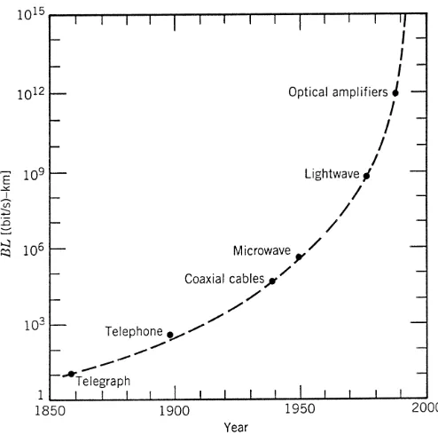
Figure 1.2: Increase in bit rate–distance productBLduring the period 1850–2000. The emer-gence of a new technology is marked by a solid circle.
the range of 1–10 GHz is used to transmit the signal by using suitable modulation techniques.
The first microwave system operating at the carrier frequency of 4 GHz was put into service in 1948. Since then, both coaxial and microwave systems have evolved considerably and are able to operate at bit rates∼100 Mb/s. The most advanced coax-ial system was put into service in 1975 and operated at a bit rate of 274 Mb/s. A severe drawback of such high-speed coaxial systems is their smallrepeater spacing(∼1 km), which makes the system relatively expensive to operate. Microwave communication systems generally allow for a larger repeater spacing, but their bit rate is also limited by the carrier frequency of such waves. A commonly used figure of merit for commu-nication systems is thebit rate–distance product,BL, whereBis the bit rate andLis the repeater spacing. Figure 1.2 shows how theBLproduct has increased through tech-nological advances during the last century and a half. Communication systems with BL∼100 (Mb/s)-km were available by 1970 and were limited to such values because of fundamental limitations.
1980 1985 1990 1995 2000 2005 Year
0.01 0.1 1 10 100 1000 10000
Bit Rate (Gb/s)
Research
Commercial
Figure 1.3: Increase in the capacity of lightwave systems realized after 1980. Commercial systems (circles) follow research demonstrations (squares) with a few-year lag. The change in the slope after 1992 is due to the advent of WDM technology.
advanced during the 1960s [6], the most noteworthy being the idea of light confinement using a sequence of gas lenses [7].
It was suggested in 1966 that optical fibers might be the best choice [8], as they are capable of guiding the light in a manner similar to the guiding of electrons in cop-per wires. The main problem was the high losses of optical fibers—fibers available during the 1960s had losses in excess of 1000 dB/km. A breakthrough occurred in 1970 when fiber losses could be reduced to below 20 dB/km in the wavelength region near 1µm [9]. At about the same time, GaAs semiconductor lasers, operating contin-uously at room temperature, were demonstrated [10]. The simultaneous availability of compactoptical sources and alow-lossoptical fibers led to a worldwide effort for de-veloping fiber-optic communication systems [11]. Figure 1.3 shows the increase in the capacity of lightwave systems realized after 1980 through several generations of devel-opment. As seen there, the commercial deployment of lightwave systems followed the research and development phase closely. The progress has indeed been rapid as evi-dent from an increase in the bit rate by a factor of 100,000 over a period of less than 25 years. Transmission distances have also increased from 10 to 10,000 km over the same time period. As a result, the bit rate–distance product of modern lightwave systems can exceed by a factor of 107compared with the first-generation lightwave systems.
1.1.2
Evolution of Lightwave Systems
1.1. HISTORICAL PERSPECTIVE 5
Figure 1.4: Increase in theBLproduct over the period 1975 to 1980 through several generations of lightwave systems. Different symbols are used for successive generations. (After Ref. [12];
c
2000 IEEE; reprinted with permission.)
generation,BLincreases initially but then begins to saturate as the technology matures. Each new generation brings a fundamental change that helps to improve the system performance further.
The first generation of lightwave systems operated near 0.8µm and used GaAs semiconductor lasers. After several field trials during the period 1977–79, such systems became available commercially in 1980 [13]. They operated at a bit rate of 45 Mb/s and allowed repeater spacings of up to 10 km. The larger repeater spacing compared with 1-km spacing of coaxial systems was an important motivation for system design-ers because it decreased the installation and maintenance costs associated with each repeater.
I