SystemVerilog
Assertions
and Functional
Coverage
Ashok B. Mehta
Ashok B. Mehta
SystemVerilog Assertions
and Functional Coverage
Guide to Language, Methodology
and Applications
Ashok B. Mehta Los Gatos, CA USA
ISBN 978-1-4614-7323-7 ISBN 978-1-4614-7324-4 (eBook) DOI 10.1007/978-1-4614-7324-4
Springer New York Heidelberg Dordrecht London
Library of Congress Control Number: 2013935401
Springer Science+Business Media New York 2014
This work is subject to copyright. All rights are reserved by the Publisher, whether the whole or part of the material is concerned, specifically the rights of translation, reprinting, reuse of illustrations, recitation, broadcasting, reproduction on microfilms or in any other physical way, and transmission or information storage and retrieval, electronic adaptation, computer software, or by similar or dissimilar methodology now known or hereafter developed. Exempted from this legal reservation are brief excerpts in connection with reviews or scholarly analysis or material supplied specifically for the purpose of being entered and executed on a computer system, for exclusive use by the purchaser of the work. Duplication of this publication or parts thereof is permitted only under the provisions of the Copyright Law of the Publisher’s location, in its current version, and permission for use must always be obtained from Springer. Permissions for use may be obtained through RightsLink at the Copyright Clearance Center. Violations are liable to prosecution under the respective Copyright Law. The use of general descriptive names, registered names, trademarks, service marks, etc. in this publication does not imply, even in the absence of a specific statement, that such names are exempt from the relevant protective laws and regulations and therefore free for general use.
While the advice and information in this book are believed to be true and accurate at the date of publication, neither the authors nor the editors nor the publisher can accept any legal responsibility for any errors or omissions that may be made. The publisher makes no warranty, express or implied, with respect to the material contained herein.
Printed on acid-free paper
To
My dear wife Ashraf Zahedi
and
Foreword
Louis H. Sullivan, an American architect, considered the father of the modern skyscraper, and mentor to Frank Lloyd Wright, coined the phrase ‘‘form follows function.’’ The actual quote is ‘‘form ever follows function’’ which is a bit more poetic and assertive than the version that has found its way into the common vernacular. He wrote those words in an article written for Lippincott’s Magazine #57 published in March 1896. Here is the passage in that article that contains the famous quote:
‘‘Whether it be the sweeping eagle in his light or the open apple-blossom, then toiling work horse, the blithe swan, the branching oak, the winding stream at its base, the drifting clouds—over all the coursing sun, form ever follows function, and this is the law. Where function does not change, form does not change. The granite rocks, the ever brooding hills, remain for ages; the lightning lives, comes into shape, and dies, in a twinkling.
It is the pervading law of all things organic and inorganic, of all things physical and metaphysical, of all things human and all things superhuman—of all true manifestations of the head, of the heart, of the soul—that the life is recognizable in its expression, that form ever follows function. This is the law.’’
Earlier in the article, Sullivan foreshadows his thought with this passage:
‘‘All things in nature have a shape, that is to say, a form, an outward semblance, that tells us what they are, that distinguishes them from ourselves and from each other.’’
The precise meaning of this pithy phrase has been debated in art and archi-tecture circles since Sullivan’s article was first published. However, it is widely accepted to mean that the form of something—its shape, color, size, etc.—is related to what it does. Water flows, rocks sit, and birds fly.
In his book ‘‘The Design of Everyday Things,’’(Basic Books 1988) Don Nor-man discusses a similar concept, the notion of affordances. NorNor-man defines the term as ‘‘… the perceived and actual properties of the thing, primarily those fundamental properties that determine just how the thing could possibly be used.’’ He cites some examples: ‘‘A chair affords (‘‘is for’’) support and, therefore, affords sitting. A chair can also be carried. Glass is for seeing through, and for breaking. Wood is normally used for solidity, opacity, support or carving.’’
Norman’s idea turns Sullivan’s upside down. He is saying function follows form. The shape, color, size, etc., of an object affects what it does. Nonetheless, both men would likely agree that form and function, whichever drives the other, are inextricably linked.
Software designers have the luxury of choosing the form to fit the function. They are not as constrained by the laws of physics as say, a cabinetmaker. The cabinetmaker must choose materials that will not only look nice, but will withstand the weight of books or dishes or whatever is to be placed on the shelves. Software designers have some constraints with regard to memory space and processing time, but beyond that they have a lot of freedom to build whatever comes to mind.
Sullivan referred to ‘‘all things physical and metaphysical.’’ Without much of a stretch we can interpret that to include software, a most abstract human creation. The form of a piece of software is linked to its function. The complex software that verification engineers build, called a testbench, must be designed before it can be built. The verification engineer, like an architect, must determine the form of his creation.
The architecture space is wide open. Computer code, while much more abstract than say, a staircase or a door handle on a car, has a form and a function. The form of computer code is the set of syntactic elements strung together in a program. The function is what the program does when executed, often referred to as its semantics.
A verification engineer is typically presented a set of requirements, often as a design specification, and asked to build a testbench that meets these requirements. Because of the tremendous flexibility afforded by the software medium he must choose the form carefully to ensure that not only meets the requirements, but is easy to use, reusable, and robust. He must choose a form that fits the function.
Often an assertion is just the right thing to capture the essence of some part of a design. Theformof an assertion is short sequence of text that can be inserted easily without disrupting the design. With their compact syntax and concise semantics assertions can be used to check low-level invariants, protocols, or end-to-end behavior.
Thefunctionof an assertion, in a simulation context, is to assert that something is always (or never) the case. It ensures that invariants are indeed invariant. Assertions can operate as checkers or as coverpoints. The fact that they can be included in-line in RTL code or in separate checkers, they can be short or long for simple or complex checking makes them invaluable in any testbench.
The wise verification engineer uses all the tools as his disposal to create an effective and easy to use testbench. He will consider the function of the testbench and devise a form that suits the required function. Assertions are an important part of any testbench.
Ashok Mehta has written a book that makes assertions accessible. His approach is very pragmatic, choosing to show you how to build and use assertions rather than engage in a lot of theoretical discussion. Not that theoretical discussion is
irrelevant—it is useful to understand the theoretical underpinnings of any tech-nology. However, there are many other books on that topic. This book fills a gap for practicing engineers where before no text provided the how-tos of building and using assertions in a real-world context.
Ashok opens up the world of assertions to verification engineers who may have thought them too opaque to consider using in a real testbench. He does an espe-cially nice job of deconstructing assertions to show how they work and how to write them. Through detailed examples he shows all the pieces that go into cre-ating assertions of different kinds, and how they fit together. Ashok completes the picture by demonstrating how assertions and coverage fit together.
Part of the book is devoted to functional coverage. He deconstructs the sometimes awkward SystemVerilog syntax of covergroups and coverpoints. Like he has with assertions, he takes the mystery out of building a high-quality coverage model.
With the mysteries of assertions unmasked, you can now include them in your personal vocabulary of testbench forms. This will enable you to create testbenches with more sophisticated function.
February 2013 Mark Glasser
Preface
Having been an end user of EDA tools for over 20 years, I have seen that many new technologies stay on way side, because either the engineers do not have time to learn of new technologies/languages or the available material is too complex to digest. A few years back I decided to tackle this problem by creating a very practical, application-oriented down-to-earth SystemVerilog Assertions (SVA) and Functional Coverage (FC) class for professional engineers. The class was well received and I received a lot of feedback on making the class even more useful. That culminated in over 500 slides of class material just on SVA and FC. Many suggested that I had collected enough material for a book. That is how I ended up on this project with the same goal that the reader should understand the concept clearly in an easy and intuitive manner and be able to apply the concepts to real-life applications right away.
The style of the book is such that the concepts are clarified directly in a slide style diagram with talking points. This will hopefully make it easy to use the book as a quick reference as well. Applications immediately following a topic will further clarify the subject matter and my hope is that once you understand the semantics and applications of a given topic, you are ready to apply that to your daily design work. These applications are modeled such that you should be able to use them in your design with minimal modifications.
This book is meant for both design and verification engineers. As a matter of fact, I have devoted a complete section on the reasons and practicality behind having micro-level assertions written by the design engineers and macro-level assertions written by verification engineers. Gone are the days when designers would write RTL and throw it over the wall for the verification engineer to quality check.
Chapter 1is Introduction to SVA and FC giving a brief history of SVA evo-lution. It also explains how SVA and FC fall under SystemVerilog umbrella to provide a complete assertions and functional coverage driven methodology.
Part I: System Verilog Assertions (SVA)
Chapter 2goes in-depth on SVA-based methodology providing detail that you can right away use in your project execution. Questions like ‘‘How do I know I have added enough assertions?’’, ‘‘What type of assertions should I add’’, etc. are explained with clarity.
Chapter 3 describes Immediate Assertions. These are nontemporal assertions allowed in procedural code.
Chapter 4goes into the fundamentals of Concurrent Assertions to set the stage for the rest of the book. How the concurrent multi-threaded semantics work, when and how assertions get evaluated in a simulation time tick, formal arguments, disabling, etc., are described here.
Chapter 5describes the so-called sampled value functions such as $rose, $fell, $stable, $past etc.
Chapter 6is the big one! This chapter describes all the operators offered by the language including Clock Delay with and without range, Consecutive repetition with and without range, nonconsecutive repetition with and without range, ‘throughout’, ‘within’, ‘and’, ‘or’, ‘intersect’, ‘first_match’, ‘if..else’, etc. Each of the operator description is immediately followed by examples and applications to solidify the concept.
Chapter 7 describes the System Functions and Tasks such as $isunknown, $onehot, etc.
Chapter 8discusses a very important aspect of the language that being prop-erties with multiple clocks. There is not a single design now a day that uses only a single clock. A simple asynchronous FIFO will have a Read Clock and a Write Clock which are asynchronous. Properties need to be written such that check in one clock domain triggers a check in another clock domain. The chapter goes in plenty detail to demystify semantics to write assertions that cross clock domains. The so-called CDC (Clock Domain Crossing) assertions are explained in this chapter.
Chapter 9is probably the most useful one describing Local Variables. Without this multi-threaded feature many of the assertions would be impossible to write. There are plenty of examples to help you weed through the semantics.
Chapter 10is on recursive properties. These are rarely used but are very handy when you want to know that a property holds until another becomes true or false. Chapters 11–13describe other useful features such as ‘expect’, ‘assume’, and detecting end point of a sequence. The ended and matched end-points of sequences are indeed very practical features.
Chapter 14is entirely devoted to very powerful and practical features that do not quite fit elsewhere. Of main interest here are the examples/testbench for asynchronous fifo checks, concurrent assertions in procedural code, sequence in Verilog ‘always’ block sensitivity list, and the phenomenon of a ‘vacuous pass’! Chapter 15is solely devoted to Asynchronous assertions. The example in this chapter shows why you need to be extremely careful in using such assertions.
Chapter 16 is entirely devoted to 1800-2009 features. There are many useful features added by the language designers. Now if only the EDA vendors would get on board and support them!
Chapter 17describes six LABs for you to try out. The LABs start with simple example moving gradually onto complex ones.
Note The LABs are available on Springer download siteextras.springer.com. All required Verilog files, test benches, and run scripts are included for both PC and Linux OS.
Chapter 18provides answers to the LABs ofChap. 17.
Part II: System Verilog Functional Coverage (FC)
Chapter 19provides introduction to Functional Coverage and explains differences with Code Coverage.
Chapter 20is fully devoted to Functional Coverage including in-depth detail on Covergroups, Coverpoints, and Bins including transition and cross coverage.
Chapter 21 provides practical hints to performance implications of coverage methodology. Do not try to cover everything all the time.
Chapter 22 describes Coverage Options, which you may keep in your back pocket as reference material for a rainy day!
Acknowledgments
I am very grateful to many who helped with review and editing of the book, in particular, Mark Glasser for his excellent foreword and in-depth review of the book, Vijay Akkati for detailed review of the chapters and many good suggestions and Sandeep Goel for motivation as well as editing of the book. I would also like to thank Bob Slee, Tom Slee, Norbert Eng, Joe Chang, and Frank Lee for all things verification.
And last but certainly not the least, I would like to thank my wife Ashraf Zahedi for enthusiasm and encouragement throughout the writing of this book and putting up with long nights and weekends required to finish the book. She is the corner-stone of my life always with a positive attitude to carry the day through up and down of life.
Contents
1 Introduction. . . 1
1.1 How Will This Book Help You? . . . 4
1.2 SystemVerilog Assertions and Functional Coverage Under IEEE 1800 SystemVerilog Umbrella . . . 5
2.2.3 Assertions Provide Temporal Domain Functional Coverage . . . 12
2.7 A Simple PCI Read Example: Creating an Assertions Test Plan . . . 22
4 Concurrent Assertions: Basics (Sequence, Property, Assert). . . 33
4.1 Implication Operator, Antecedent and Consequent . . . 37
4.3 Sampling Edge (Clock Edge) Value: How are Assertions
4.7 Severity Levels (for Both Concurrent and Immediate Assertions) . . . 52
6.2.1 Clock Delay Range Operator: ## [m:n] :: Multiple Threads . . . 75
6.2.2 Clock Delay Range Operator :: ##[m:n] (m=0; n=$) . . . 77
6.3 [*m]: Consecutive Repetition Operator . . . 78
6.4 [*m:n]: Consecutive Repetition Range. . . 80
6.8 Difference Between [=m:n] and [-[m:n] . . . 94
6.17 if (expression) property_expr1 else property_expr2 . . . 120
6.17.1 Application: if then else . . . 121
8.1 Multiply Clocked Sequences and Property Operators . . . 131
8.1.1 Multiply Clocked Sequences . . . 132
8.1.2 Multiply Clocked Sequences: Legal and Illegal Sequences . . . 133
8.1.3 Multiply Clocked Properties—‘and’ Operator. . . 134
8.1.4 Multiply Clocked Properties—‘or’ Operator. . . 136
8.1.5 Multiply Clocked Properties—‘not’ Operator . . . 137
8.1.6 Multiply Clocked Properties—Clock Resolution . . . . 138
8.1.7 Multiply Clocked Properties—Legal and Illegal Conditions . . . 141
9 Local Variables . . . 143
14.2 Embedding Concurrent Assertions in Procedural Code . . . 183
14.3 Calling Subroutines. . . 186
14.4 Sequence as a Formal Argument . . . 189
14.5 Sequence as an Antecedent . . . 189
14.6 Sequence in Sensitivity List . . . 191
14.7 Building a Counter . . . 192
14.8 Clock Delay: What if You WantVariable Clock Delay? . . . . 193
14.9 What if the ‘action block’ is Blocking? . . . 195
14.10 Interesting Observation with Multiple Implications in a Property. Be Very Careful…. . . . 198
14.15.1 Concurrent Assertion–Without-an Implication . . . 202
14.15.2 Concurrent Assertion–with-an Implication . . . 203
14.15.3 Vacuous Pass. What? . . . 205
14.15.4 Concurrent Assertion–with ‘cover’ . . . 205
14.16 Empty Sequence . . . 206
15 Asynchronous Assertions !!! . . . 211
16 IEEE-1800-2009 Features. . . 215
16.1 Strong and Weak Sequences . . . 215
16.2 Deferred Assertions. . . 216
16.3 $changed . . . 217
16.4 $sampled . . . 218
16.5 $past_gclk, $rose_gclk, $fell_gclk, $stable_gclk, $changed_gclk, $future_gclk, $rising_gclk,
16.10 until, s_until, until_with and s_until_with Properties . . . 225
16.11 nexttime and s_nexttime . . . 227
16.14.3 Let: In Immediate and Concurrent Assertions. . . 234
16.15 ‘restrict’ for Formal Verification. . . 236
16.16 Abort Properties: reject_on, accept_on, sync_reject_on, sync_accept_on . . . 237
16.17 $assertpassoff, $assertpasson, $assertfailoff, $assertfailon, $assertnonvacuouson, $assertvacuousoff. . . 240
17.5 LAB5: Data Transfer Protocol . . . 283
18.2 LAB2: Answers : Overlap and Non-Overlap Operators . . . 300
18.3 LAB3: Answers : FIFO . . . 304
18.4 LAB4: Answers : Counter . . . 306
18.5 LAB5: Answers : Data Transfer Protocol . . . 308
18.6 LAB6: Answers . . . 310
19 Functional Coverage. . . 313
19.1 Difference Between Code Coverage and Functional Coverage . . . 313
19.2 Assertion Based Verification and Functional Coverage Based Methodology . . . 314
20.4.1 Covergroup/Coverpoint with bins: Example…. . . . . 325
20.4.2 SystemVerilog ‘covergroup’:
21.4 Application: Have you Transmitted All Different Lengths of a Frame? . . . 343
22 Coverage Options (Reference Material). . . 345 22.1 Coverage Options: Instance Specific—Example . . . 347 22.2 Coverage Options: Instance Specific Per-Syntactic Level. . . . 348 22.3 Coverage Options for ‘Covergroup’ Type: Example . . . 350
Index . . . 353
Figures
Fig. 1.1 Verification cost increases as the technology node shrinks Fig. 1.2 Design productivity and design complexity
Fig. 1.3 SystemVerilog assertions and functional coverage components under SystemVerilog IEEE 1800-2009 umbrella
Fig. 1.4 SystemVerilog evolution
Fig. 1.5 SystemVerilog assertion evolution
Fig. 2.1 A simple bus protocol design and its SVA property Fig. 2.2 Verilog code for the simple bus protocol
Fig. 2.3 Assertions improve observability
Fig. 2.4 SystemVerilog assertions provide temporal domain functional coverage
Fig. 2.5 Assertions for hardware emulation
Fig. 2.6 Assertions and assumptions in formal (static functional) and simulation
Fig. 2.7 Assertions and OVL for different uses Fig. 2.8 A simple PCI read protocol
Fig. 3.1 Immediate assertion—basics Fig. 3.2 Immediate assertions : finer points Fig. 4.1 Concurrent assertion—basics
Fig. 4.2 Concurrent assertion—sampling edge and action blocks Fig. 4.3 Concurrent assertion—implication, antecedent
and consequent
Fig. 4.4 Property with an embedded sequence
Fig. 4.5 Implication operator—overlapping and nonoverlapping Fig. 4.6 Equivalence between overlapping and nonoverlapping
implication operators Fig. 4.7 Clocking basics
Fig. 4.8 Clocking basics—clock in ‘assert’, ‘property’ and ‘sequence’
Fig. 4.9 Assertions variable sampling and evaluation/execution in a simulation time tick
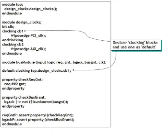
Fig. 4.10 Default clocking block
Fig. 4.11 ‘clocking’ and ‘default clocking’ Fig. 4.12 Gated clock
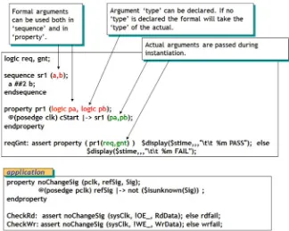
Fig. 4.13 Multi-threaded concurrent assertions Fig. 4.14 Formal and actual arguments
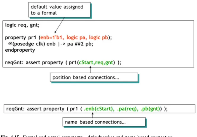
Fig. 4.15 Formal and actual arguments—default value and name-based connection
Fig. 4.16 Formal and actual arguments—default value and position-based connection
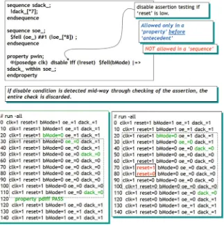
Fig. 4.17 Passing event control to a formal Fig. 4.18 ‘disable iff’ operator
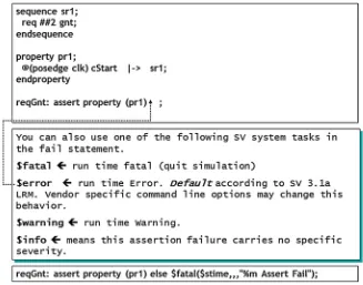
Fig. 4.19 Severity levels for concurrent and immediate assertions Fig. 4.20 Binding properties
Fig. 4.21 Binding properties to design ‘module’ internal signals (scope visibility)
Fig. 4.22 Binding properties to an existing design. Assertions adoption in the existing design
Fig. 5.1 Sampled value functions $rose, $fell—basics Fig. 5.2 $rose—basics
Fig. 5.3 Usefulness of ‘edge’ detection and performance implication
Fig. 5.4 $rose—finer points Fig. 5.5 $fell—basics
Fig. 5.6 $rose and $fell in procedural block and continuous assignment
Fig. 5.7 $stable—basics
Fig. 5.8 $stable in procedural block Fig. 5.9 $past—basics
Fig. 5.10 $past—gating expression
Fig. 5.11 $past—gating expression—simulation log Fig. 5.12 $past application
Fig. 5.13 $past rescues $fell Fig. 6.1 ##m Clock delay—basics Fig. 6.2 ##m Clock delay with m=0 Fig. 6.3 ##0—application
Fig. 6.4 ##[m:n] Clock delay range Fig. 6.5 ##[m:n]—multiple threads
Fig. 6.6 ##[m:n] Clock delay range with m=0 and n=$ Fig. 6.7 ##[1:$] Delay range application
Fig. 6.8 [*m]—Consecutive repetition operator—basics Fig. 6.9 [*m] Consecutive repetition operator—application Fig. 6.10 [*m:n] Consecutive repetition range—basics Fig. 6.11 [*m:n] Consecutive repetition range—example Fig. 6.12 [*m:n] Consecutive repetition range—application
Fig. 6.13 [*m:n] Consecutive repetition range—application Fig. 6.14 [*m:n] Consecutive repetition range—application Fig. 6.15 [*m:n] Consecutive repetition range—application Fig. 6.16 Design application
Fig. 6.17 Design application—simulation log
Fig. 6.18 Repetition nonconsecutive operator—basics Fig. 6.19 Non-consecutive repetition operator—example Fig. 6.20 Repetition nonconsecutive range—basics Fig. 6.21 Repetition nonconsecutive range—application Fig. 6.22 Repetition nonconsecutive range—[= 0:$] Fig. 6.23 GoTo nonconsecutive repetition—basics Fig. 6.24 Non-consecutive repetition—example Fig. 6.25 Difference between [= m:n] and [-[m:n]
Fig. 6.26 GoTo repetition—nonconsecutive operator—application Fig. 6.27 sig1 throughout seq1
Fig. 6.28 sig1 throughout seq1—application Fig. 6.29 sig1 throughout seq1—application Fig. 6.30 seq1 withinseq2
Fig. 6.31 seq1 withinseq2—application
Fig. 6.32 within operator—simulation log example—PASS cases Fig. 6.33 within operator—simulation log example—FAI cases Fig. 6.34 seq1 andseq2—basics
Fig. 6.35 and operator—application Fig. 6.36 and operator—application-II Fig. 6.37 and of expressions
Fig. 6.38 seq1 or seq2—basics Fig. 6.39 oroperator—application Fig. 6.40 or operator—application II Fig. 6.41 or operator—application III Fig. 6.42 ofexpressions
Fig. 6.43 seq1 intersect seq2
Fig. 6.44 seq1 ‘intersect’ seq2—application Fig. 6.45 seq1 intersect seq2—application II
Fig. 6.46 intersectmakes sense with subsequences with ranges Fig. 6.47 Intersect operator : interesting application
Fig. 6.48 and versus intersect what’s the difference Fig. 6.49 first_match—application
Fig. 6.56 if…else—application
Fig. 7.1 onehot and $onehot0 Fig. 7.2 isunknown
Fig. 7.3 $ISUNKNOWN application Fig. 7.4 $countones—basics and application Fig. 7.5 $countones application
Fig. 7.6 $countones as boolean
Fig. 7.7 $assertoff, $asserton, $assertkill—basics Fig. 7.8 Assert control application
Fig. 8.1 Multiply clocked sequences—basics
Fig. 8.2 Multiply clocked sequences—identical clocks
Fig. 8.3 Multiply clocked sequences—illegal conditions – ONLY FOR 1800-2005. Limitation removed from 1800-2009 Fig. 8.4 Multiply clocked properties—‘and’ operator between
two different clocks
Fig. 8.5 Multiply clocked properties—‘and’ operator between same clocks
Fig. 8.6 Multiply clocked properties—‘or’ operator Fig. 8.7 Multiply clocked properties—‘not’ operator Fig. 8.8 Multiply clocked properties—clock resolution Fig. 8.9 Multiply clocked properties—clock resolution—II Fig. 8.10 Multiply clocked properties—clock resolution—III Fig. 8.11 Multiply clocked properties—legal and illegal conditions Fig. 9.1 Local variables—basics
Fig. 9.2 Local variables—Do’s and Don’ts Fig. 9.3 Local variables—and formal argument Fig. 9.4 Local variables—visibility
Fig. 9.5 Local variable composite sequence with an ‘OR’ Fig. 9.6 Local variables—for an ‘OR’ assign local
data—before-the composite sequence
Fig. 9.7 Local variables—assign local data in both operand sequences of ‘OR’
Fig. 9.8 Local variables—‘and’ of composite sequences Fig. 9.9 Local variables—finer nuances III
Fig. 9.10 Local variables—further nuances IV
Fig. 9.11 Local variable cannot be used in delay range Fig. 9.12 Local variables—cannot use a ‘formal’ to size
a local variable
Fig. 9.13 Local variables—application Fig. 10.1 Recursive property—basics Fig. 10.2 Recursive property—application Fig. 10.3 Recursive property—application Fig. 10.4 Recursive property—further nuances I Fig. 10.5 Recursive Property—further nuances II Fig. 10.6 Recursive property—mutually recursive
Fig. 11.1 ended—end point of a sequence Fig. 11.2 ended with overlapping operator Fig. 11.3 ended with non-overlapping operator Fig. 11.4 matched—basics
Fig. 11.5 matched with non-overlapping operator Fig. 11.6 matched—overlapped operator
Fig. 11.7 matched—application Fig. 12.1 expect’—basics
Fig. 12.2 ‘expect’—error conditions Fig. 13.1 ‘assume’ and formal verification
Fig. 14.1 Embedding concurrent assertions in procedural code Fig. 14.2 Concurrent assertion embedded in procedural code
is nonblocking
Fig. 14.3 Embedding concurrent assertions in procedural code—further nuances
Fig. 14.4 Calling subroutines
Fig. 14.5 Calling subroutines—further nuances
Fig. 14.6 Calling subroutines and local variables—application Fig. 14.7 Sequence as a formal argument
Fig. 14.8 Sequence as an antecedent
Fig. 14.9 Sequence in procedural block sensitivity list Fig. 14.10 Sequence in ‘sensitivity’ list
Fig. 14.11 Building a counter using local variables Fig. 14.12 Variable delay—problem statement Fig. 14.13 Variable delay—solution
Fig. 14.14 Blocking action block
Fig. 14.15 Blocking versus non-blocking action block Fig. 14.16 Multiple implications in a property
Fig. 14.17 Subsequence in a sequence—clock inference Fig. 14.18 Subsequence in a sequence
Fig. 14.19 Cyclic dependency Fig. 14.20 Refinements on a theme
Fig. 14.21 Simulation performance efficiency Fig. 14.22 Assertion without implication operator Fig. 14.23 Assertion resulting in vacuous pass Fig. 14.24 Assertion with ‘cover’ for PASS Fig. 14.25 Empty match [*m] where m=0 Fig. 14.26 empty match—example Fig. 14.27 empty match example—II Fig. 14.28 empty sequence. Further rules
Fig. 15.1 Asynchronous assertion—problem statement Fig. 15.2 Asynchronous Assertion—problem statement
analysis continued
Fig. 15.3 Asynchronous assertion—solution Fig. 16.1 $changed
Fig. 17.1 LAB1: ‘bind’ assertions. Problem definition Fig. 17.2 LAB3: Synchronous FIFO: Problem definition Fig. 17.3 LAB4 : Counter : Problem definition
Fig. 17.4 LAB5: Data Transfer Protocol : Problem definition Fig. 17.5 LAB6: PCI Protocol: Problem Definition
Fig. 18.1 LAB1: ‘bind’ assertions (answers)
Fig. 18.2 LAB1: Q&A on ‘no_implication’ operator (answers) Fig. 18.3 LAB1: Q&A on ‘implication’ operator (answers) Fig. 18.4 LAB1: Q&A on ‘overlap’ operator (answers) Fig. 18.5 LAB1: Q&A on ‘non-overlap’ operator (answers) Fig. 18.6 LAB3: FIFO: Answers
Fig. 18.7 LAB4: Counter : Answers
Fig. 18.8 LAB5: Data Transfer Bus Protocol: Answers Fig. 18.9 LAB6: PCI Protocol: Answers
Fig. 19.1 Assertion based verification (ABV) and functional coverage (FC) based methodology
Fig. 19.2 Assertions and coverage closed loop verification methodology—I
Fig. 19.3 Assertion and functional coverage closed loop verification methodology—II
Fig. 20.1 ‘covergroup’ and ‘coverpoint’—basics Fig. 20.2 ‘coverpoint’—basics
Fig. 20.3 ‘covergroup’/‘coverpoint’ example Fig. 20.4 ‘bins’ - basics
Fig. 20.5 ‘covergroup’/‘coverpoint’ example with ‘bins’ Fig. 20.6 ‘covergroup’—formal and actual arguments Fig. 20.7 ‘covergroup’ in as SystemVerilog class
(courtesy LRM 1800-2005)
Fig. 20.8 multiple ‘covergroup’ in a SystemVerilog class Fig. 20.9 ‘cross’ coverage—basics
Fig. 20.10 ‘cross’ coverage—simulation log Fig. 20.11 ‘cross’—bxample (further nuances) Fig. 20.12 ‘cross’ example—simulation log Fig. 20.13 ‘bins’ for transition coverage
Fig. 20.14 ‘bins’—transition coverage further features Fig. 20.15 ‘bins’ for transition—example with simulation log Fig. 20.16 Example of PCI cycles transition coverage Fig. 20.17 wildcard ‘bins’
Fig. 20.18 ‘ignore_bins’—basics Fig. 20.19 ‘illegal_bins’
Fig. 20.20 ‘binsof’ and ‘intersect’
Fig. 21.1 Functional coverage—performance implication Fig. 21.2 Application—Have you transmitted all different
lengths of a frame?
Fig. 22.1 Coverage options—reference material
Fig. 22.2 Coverage options—instance specific—example
Fig. 22.3 Coverage options—instance specific per-syntactic level Fig. 22.4 Coverage options type specific per syntactic level. Fig. 22.5 Coverage options for ‘covergroup’ type
specific—comprehensive example
Fig. 22.6 Predefined coverage system tasks and functions
Tables
Table 2.1 PCI read protocol test plan by functional verification team Table 2.2 PCI read protocol test plan by design team
Table 2.3 Conventions used in this book Table 6.1 Concurrent assertion operators
Chapter 1
Introduction
As is well known in the industry, the design complexity at 28 nm node and below is exploding. Small form factor requirements and conflicting demands of high performance and low power and small area result in ever so complex design architecture. Multi-core, multi-threading and Power, Performance and Area (PPA) demands exacerbate the design complexity and functional verification thereof.
The burden lies on functional and temporal domain verification to make sure that the design adheres to the specification. Not only is RTL (and Virtual Platform level) functional verification important but so is silicon validation. Days when engineering teams would take months to validate the silicon in the lab are over. What can you do during pre-silicon verification to guarantee post-silicon valida-tion is a first pass success.
Fig. 1.1 Verification cost increases as the technology node shrinks
A. B. Mehta,SystemVerilog Assertions and Functional Coverage, DOI: 10.1007/978-1-4614-7324-4_1,
Springer Science+Business Media New York 2014
The biggest challenge that the companies face is short time-to-market to deliver first pass working silicon of increasing complexity. Functional design verification is the long poll to design tape-out. Here are two key problem statements. 1. Design Verification Productivity :: 40–50 % of project resources go to
func-tional design verification. The chart in Fig.1.1shows design cost for different parts of a design cycle. As is evident, the design verification cost component is about 40+ % of the total design cost. In other words, this problem states that we must increase the productivity of functional design verification and shorten the design ,simulate,debug,cover loop. This is a productivity issue, which needs to be addressed (Fig.1.2).
Continuing with the productivity issue, the following chart shows that the compounded complexity growth rate per year is 58 % while the compounded pro-ductivity growth rate is only 21 %. There is a huge gap between whatneedsto get done and whatisgetting done. This is another example of why the productivity of design cycle components such as functional design verification must be improved.
2. Design Coverage :: The second problem statement states that more than 50 % of designs require re-spin due to functional bugs. One of the factors that con-tribute to this is the fact that we did not objectively determinebeforetape-out that we had really covered the entire design space with our test-bench. The motto ‘‘If it’s not verified, it will not work’’ seems to have taken hold in design cycle. Not knowing if you have indeed covered the entire design space is the real culprit towards escaped bugs and functional silicon failures.
So, what’s the solution to each problem statement?
Fig. 1.2 Design productivity and design complexity
1. Increase Design Verification Productivity a. Reduce Time to Develop
i. Raise abstraction level of tests. Use TLM (Transaction Level Modeling) based methodologies such as UVM, SystemVerilog/C++/DPI, etc. The higher the abstraction level, easier it is to model and maintain verification logic. Modification and debug of transaction level logic is much easier, further reducing time to develop test-bench, reference models (scoreboard), peripheral models and other such verification logic.
ii. Use constrained random verification (CRV) methodologies to reach exhaustive coverage with fewer tests. Fewer tests mean less time to develop and debug.
iii. Develop Verification Components (UVM agents, for example) that are reusable. Make them parameterized for adoptability in future projects. iv. Use SystemVerilog Assertions to reduce time to develop complex temporal
domain and combinatorial checks. As we will see, assertions are intuitive and much simpler to model, especially for complex temporal domain checks. Verilog code for a given assertion will be much more lengthy, hard to model and hard to debug. SVA indeed reduces time to develop and debug.
b. Reduce Time to Simulate
i. Again, higher level of abstraction simulate much faster than pure RTL test bench which is modeled at signal level. Use transaction level test bench. ii. Use SystemVerilog Assertions to directly point to the root cause of a bug.
This reduces the simulate,debug,verify loop time. Debugging the design is time consuming as is, but not knowing where the bug is and trial and error simulations further exacerbate the already lengthy simulation time.
c. Reduce Time to Debug
i. Use SystemVerilog Assertion Based Verification (ABV) methodology to quickly reach to the source of the bug. As we will see, assertions are placed at various places in design to catch bugs where they occur. Traditional way of debug is at IO level. You see the effect of a bug at primary output. You then trace back from primary output until you find the cause of the bug resulting in lengthy debug time. In contrast, an SVA assertion points directly at the source of the failure (for example, a FIFO assertion will point directly to the FIFO condition that failed and right away help with debug of the failure) drastically reducing the debug effort.
ii. Use Transaction level methodologies to reduce debugging effort (and not get bogged down into signal level granularity)
2. Reduce Time to Coverand build confidence in taping out a fully verified design i. Use ‘cover’feature of SystemVerilog Assertions to cover complextemporal domain specification of your design. As we will see further in the book, ‘cover’ helps with making sure that you have exercised low level temporal domain conditions with your test-bench. If an assertion does not fire, that does not necessarily mean that there is no bug. One of the reasons for an assertion to not fire is that you probably never really stimulated the required condition (antecedent) in the first place. If you do not stimulate a condition, how would you know if there is indeed a bug in the design logic under simulation? ‘cover’ helps you determine if you have indeed exercised the required temporal domain condition. More on this in later chapters. ii. Use SystemVerilog Functional Coveragelanguage to measure the ‘intent’
of the design. How well have your test bench verified the ‘intent’ of the design. For example, have you verified all transition of Write/Read/Snoop on the bus? Have you verified that a CPU1-snoop occurs to the same line at the same time that a CPU2-write invalid occurs to the same line? Code Coverage will not help with this. We will cover Functional Coverage in plenty detail in the book.
iii. Use Code Coverage to coverstructuralcoverage (yes, code coverage is still important as the first line of defense even though it simply provides struc-tural coverage). As we will see in detail in the section on SV Functional Coverage, structural coverage does not verify the intent of the design, it simply sees that the code that you have written has been exercised (e.g. if you have verified all ‘case’ items of a ‘case’ statement, or toggled all pos-sible assigns, expressions, states, etc.). Nonetheless, code coverage is still important as a starting point to measure coverage of the design.
As you notice from above analysis, SystemVerilog Assertions and Functional Coverage play a key role in about every aspect of Functional Verification. Note that in this book, I use Functional Verification to include both the ‘function’ functional coverage as well as the ‘temporal’ functional coverage.
1.1 How Will This Book Help You?
This book will go systematically through each of SystemVerilog Assertions (SVA) and Functional Coverage (FC) language features and methodology components with practical applications at each step. These applications are modeled such that you should be able to use them in your design with minimal modifications. The book is organized using power point style slides and description to make it very easy to grasp the key fundamentals. Advanced applications are given for those users
who are familiar with the basics. For most part, the book concentrates on the in-depth discussion of the features of the languages and shows examples that make the feature easily understandable and applicable. Simulation logs are frequently used to make it easier to understand the underlying concepts of a feature or method.
The book is written by a design engineer for (mainly) hardware design engi-neers with the intent to make the languages easy to grasp avoiding decipher of lengthy verbose descriptions. The author have been in System and Chip design field for over 20 years and knows the importance of learning new languages and methodologies in shortest possible time to be productive.
The book concentrates on SVA features of the IEEE 1800-2005 standard. Author believes that the features of this standard are plenty to designing practical assertions for the reader’s project(s). However, the author have indeed explained IEEE 1800-2009 features in a standalone Chap. 16 to give a flavor of the new standard. Note that many of the 2009 features were not supported by popular simulators as of this writing and the examples provided were not simulated. Please do send your suggestions/corrections to the author.
1.2 SystemVerilog Assertions and Functional Coverage
Under IEEE 1800 SystemVerilog Umbrella
SystemVerilog assertions (SVA) and Functional Coverage (FC) are part of IEEE 1800 SystemVerilog standard. In other words, SVA and FC are two of the four distinct language subsets that fall under the SystemVerilog umbrella.
(1) SystemVerilog Object Oriented language for functional verification (using OVM/UVM style libraries)
(2) SystemVerilog language for Design
(3) SystemVerilog Assertions (SVA) language and
(4) SystemVerilog Functional Coverage (FC) Language to see that the verification environment/test-bench have fully verified your design.
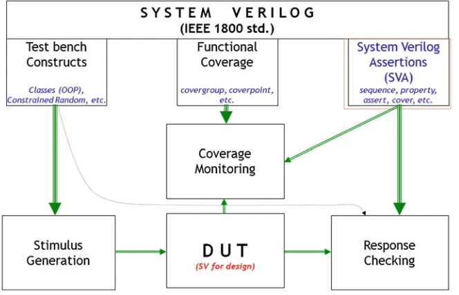
As shown in Fig.1.3, SVA and FC are two of the important language subsets of SystemVerilog.
In any design, there are 3 main components of verification. (1) Stimulus Generators to stimulate the design (2) Response Checkers to see that the device adheres to the device specifications (3) Coverage components to see that we have indeed structurally and functionally covered everything in the DUT according to the device specifications.
(1) Stimulus Generation. This entails creating different ways in which a DUT needs to be exercised. For example, a peripheral (e.g. USB) maybe modeled as a Bus Functional Mode (or a UVM (Universal Verification Methodology)
agent) to drive traffic through SystemVerilog transactions to the DUT. Dif-ferent techniques are deployed to achieve exhaustive coverage of the design. For example, constrained random, transaction based, UVM based, memory based, etc. These topics are beyond the scope of this book.
(2) Response checking. Now that you have stimulated the DUT, you need to make sure that the device has responded to that stimulus according to the device specs. Here is where SVA comes into picture along with UVM monitors, scoreboards and other such techniques. SVA will check to see that the design not only meets high level specifications but also low level combinatorial and temporal design rules.
(3) Functional Coverage. How do we know that we have exercised everything that the device specification dictates? Code Coverage is one measure. But code coverage is only structural. For example, it will point out if a conditional has been exercised. But code coverage has no idea if the conditional itself is correct, which is where Functional Coverage comes into picture (more on this later when we discuss Functional Coverage). Functional coverage gives an objective measure of the design coverage (e.g. have we verified all different cache access transitions (for example, write followed by read from the same address) to L2 from CPU? Code Coverage will not give such measure). We will discuss entire coverage methodology in detail inChap. 19.
Fig. 1.3 SystemVerilog assertions and functional coverage components under SystemVerilog IEEE 1800-2009 umbrella
1.3 SystemVerilog Assertions Evolution
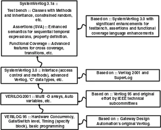
To set the stage, here is a brief history of Verilog to SystemVerilog evolution (Figs.1.4and1.5). Starting with Verilog 95, we reached Verilog 2001 with Multi-dimensional arrays and auto variables, among other useful features. Meanwhile, functional verification was eating up ever more resources of a given project. Everyone had disparate functional verification environments and methodologies around Verilog. This was no longer feasible.
Industry recognized the need for a standard language that allowed the design andverification of a device and a methodology around which reusable components can be built avoiding multi-language cumbersome environments. Enter Superlog, which was a language with high level constructs required for functional verifi-cation. Superlog was donated (along with other language subset donations) to create SystemVerilog 3.0 from which evolved SystemVerilog 3.1, which added new features for design but over 80 % of the new language subset was dedicated to functional verification. We can only thank the Superlog inventor (the same inventor as that for Verilog—namely, Phil Moorby) and the Accelera technical subcommittees for having a long term vision to design such a robust all-encom-passing language. No multi-language solutions were required any more. No more reinventing of the wheel with each project was required anymore.
VERILOG 95 :: Hardware Concurrency, Gate/Switch level, Timing (specify
block), basic programming VERILOG-2001 :: Multi -D arrays, Auto
variables, etc.
SystemVerilog 3.0 :: Interface (access control and methods), advanced
Verilog, 'C" data types, etc. SystemVerilog 3.1a :: Test bench :: Classes with Methods and Inheritance, constrained random,
etc.
Assertions (SVA) :: Enhanced semantics for sequential temporal
expressions, property definition. Functional Coverage :: Advanced
features for cross coverage, transitions, etc.
Based on :: SystemVerilog 3.0 with significant enhancements for testbench, assertions and functional
coverage language enhancements
Based on :: Verilog 95 and original effort by IEEE technical
subcommittees
Based on :: Gateway Design Automation's original Verilog. Based on :: Verilog 2001 and
SuperLog
Fig. 1.4 SystemVerilog evolution
As shown in Fig.1.5, SystemVerilog Assertion language is derived from many different languages. Features from these languages either influenced the language or were directly used as part of the language syntax/semantic.
Sugar from IBM led to PSL. Both contributed to SVA. The other languages that contributed are Vera, ‘e’, CBV from Motorola and ForSpec from Intel.
In short, when we use SystemVerilog Assertions language, we have the benefit of using the latest evolution of an assertions language that benefited from many other robust assertions languages.
Fig. 1.5 SystemVerilog assertion evolution
Chapter 2
System Verilog Assertions
2.1 What is an Assertion?
An assertion is simply a check against the specification of your design that you want to make sure never violates. If the specs are violated, you want to see a failure.
A simple example is given below. Whenever FRAME_ is de-asserted (i.e. goes High), that the Last Data Phase (LDP_) must be asserted (i.e. goes Low). Such a check is imperative to correct functioning of the given interface. SVA language is precisely designed to tackle such temporal domain scenarios. As we will see in Sect. 2.2.1, modeling such a check is far easier in SVA than in Verilog. Note also
Fig. 2.1 A simple bus protocol design and its SVA property
A. B. Mehta,SystemVerilog Assertions and Functional Coverage, DOI: 10.1007/978-1-4614-7324-4_2,
Springer Science+Business Media New York 2014
that assertions work in temporal domain (and we will cover a lot more on this later); and are concurrent as well as multi-threaded. These attributes is what makes SVA language so suitable for writing temporal domain checks.
Figure2.1 shows the assertion for this simple bus protocol. We will discuss how to read this code and how this code compares with Verilog in the immediately followingSect. 2.2.1.
2.2 Why Assertions? What are the Advantages?
As we discussed in the introductory section, we need to increase productivity of the design/debug/simulate/cover loop. Assertions help exactly in these areas. As we will see, they are easier to write than standard Verilog or SystemVerilog (thereby increasing design productivity), easier to debug (thereby increasing debug productivity), provide functional coverage and simulate faster compared to the same assertion written in Verilog or SystemVerilog. Let us see these advantages one by one.
2.2.1 Assertions Shorten Time to Develop
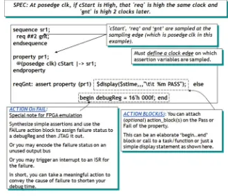
Referring to the timing diagram in Fig.2.1, let us see how SVA shortens time to develop. The SVA code is very self-explanatory. There is the property ‘ldpcheck’ that says ‘‘at posedge clock, if FRAME_ rises, it implies that within the next 2 clocks LDP_ falls’’. This is almost like writing the checker in English. We then ‘assert’ this property, which will check for the required condition to meet at every posedge clk. We also ‘cover’ this property to see that we have indeed exercised the required condition. But we are getting ahead of ourselves. All this will be explained in detail in coming chapters. For now, simply understand that the SV assertion is easy to write, easy to read and easy to debug.
Now examine the Verilog code for the same check (Fig.2.2). There are many ways to code this. One of the ways at behavioral level is shown. Here you ‘fork’ out two procedural blocks; one that monitors LDP and another that waits for 2 clocks. You then disable the entire block (‘ldpcheck’) when either of the two procedural blocks complete. As you can see that not only is the checker very hard to read/interpret but also very prone to errors. You may end up spending more time debugging your checker than the logic under verification.
2.2.2 Assertions Improve Observability
One of the most important advantage of assertions is that they fire at the source of the problem. As we will see in the coming chapters, assertions are located local to temporal conditions in your design. In other words, you don’t have to back trace a bug all the way from primary output to somewhere internal to the design where the bug originates. Assertions are written such that they are close to logic (e.g. @
Fig. 2.2 Verilog code for the simple bus protocol
Fig. 2.3 Assertions improve observability
(posedge clk) state0 |-[Read); Such an assertion is sitting close to the state machine and if the assertion fails, we know that when the state machine was in state0 that Read did not take place. Some of the most useful places to place assertions are FIFOs, Counters, block to block interface, block to IO interface, State Machines, etc. These constructs in RTL logic is where many of the bugs originate. Placing an assertion that check for local condition will fire when that local condition fails, thereby directly pointing to the source of the bug (Fig.2.3). Traditional verification can be called Black Box verification with Black Box observability, meaning, you apply vectors/transactions at the primary input of the ‘block’ without caring for what’s in the block (blackbox verification) and you observe the behavior of the block only at the primary outputs (blackbox observ-ability). Assertions on the other hand allow you to do black box verification with white box (internal to the block) observability.
2.2.3 Assertions Provide Temporal Domain Functional
Coverage
Assertions not only help you find bugs but also help you determine if you have covered (i.e. exercised) design logic, mainly temporal domain conditions. They are very useful in finding temporal domain coverage of your test-bench. Here is the reason why this is so important (Fig.2.4).
Fig. 2.4 SystemVerilog assertions provide temporal domain functional coverage
Let us say, you have been running regressions 24*7 and have stopped finding bugs in your design. Does that mean you are done with verification? No. Not finding a bug could mean one of two things. (1) There is indeed no bug left in the design or (2) you have not exercised (or covered) all the required functions of the design. You could be continually hitting the same piece of logic in which no further bugs remain. In other words, you could be reaching a wrong conclusion that all the bugs have been found.
In brief, coverage includes three components (we will discuss this in detail in Chap. 19). (1) Code Coverage (which is structural) which needs to be 100 %; (2) Functional Coverage that need to be designed to coverfunctionalityof the entire design and must be completely covered; (3) temporal domain coverage (using SVA ‘cover’ feature) which need to be carefully designed to fully cover all required temporal domain conditions of the design.
Ok, let us go back to the simple bus protocol assertion that we saw in the previous section. Let us see how the ‘cover’ statement in that SVA assertion works. The code is repeated here for readability.
In this code, you see that there is a ‘cover’ statement. What it tells you is ‘‘did you exercise this condition’’ or ‘‘did you cover this property’’. In other words and as discussed above, if the assertion never fires, that could be because of two reasons. (1) you don’t have a bug or (2) you never exercised the condition to start with! With the cover statement, if the condition gets exercised but does not fail you get that indication through the ‘pass’ action block associated with the ‘cover’ statement. Since we haven’t yet discussed the assertions in any detail, you may not completely understand this concept but determination of temporal domain cov-erage of your design is an extremely important aspect of verification and must be made part of your verification plan.
To reiterate, SVA supports the ‘cover’ construct that tells you if the assertion has been exercised (covered). Without this indication and in the absence of a failure, you have no idea if you indeed exercised the required condition. In our example, if FRAME_ never rises, the assertion won’t fire and obviously there won’t be any bug reported. So, at the end of simulation if you do not see a bug or you do not even see the ‘‘ldpcheck PASS’’ display, you know that the assertion never fired. In other words, you must see the ‘cover property’ statement executed in order to know that the condition did get exercised. We will discuss this further in coming chapters. Use ‘cover’ to full extent as part of your verification methodology.
2.2.3.1 Assertion Based Methodology Allows for Full Random Verification
Huh! What does that mean? This example, I learnt from real life experience. In our projects, we always do full random concurrent verification (i.e. all initiators of the design fire at the same time to all targets of the design) after we are done with directed and constrained random verification. The idea behind this is to find any deadlocks (or livelock for that matter) in the design. Most of the initiator tests are well crafted (i.e. they won’t clobber each other’s address space) but with such massive randomness, your target model may not be able to predict response to randomly fired transactions. In all such cases, it is best to disable scoreboards in your target models (unless the scoreboards are full proof in that they can survive total randomness of transactions) BUT keep assertions alive. Now, fire concurrent random transactions, the target models will respond the best they can but asser-tions will pin point to a problem if it exists (such as simulation hang (deadlock) or simply keep clocking without advancing functionality (livelock)).
In other words, assertions are always alive and regardless of transaction stream (random or directed), they will fire as soon as there is the detection of an incorrect condition.
• Example Problem Definition:
– Your design has Ethernet Receive and Video as Inputs and is also a PCI target.
– It also has internal initiators outputting transactions to PCI targets, SDRAM, Ethernet Transmit and Video outputs.
– After you have exhausted constrained random verification, you now want to simulate a final massive random verification, blasting transactions from all input interfaces and firing transactions from internal masters (DMA, Video Engine, Embedded processors) to all the output interfaces of the design. – BUT there’s a good chance your reference models, self-checking tests,
scoreboards may not be able to predict the correct behavior of the design under such massive randomness.
• Solution:
– Turn off all your checking (reference models, scoreboards, etc.) unless they are full proof to massive random transaction streams.
– BUT keep Assertions alive.
– Blast the design with massive randomness (keep address space clean for each initiator).
– If any of the assertions fire, you have found that corner case bug.
2.2.3.2 Assertions Help Detect Bugs not Easily Observed at Primary Outputs
This is a classic case that we encountered in a design and luckily found before tape-out. Without the help of an assertion, we would not have found the bug and there would have to be a complex software workaround. I will let the following example explain the situation.
• The Specification:
– On a store address Error, the address in Next Address Register (NAR) should be frozen the same cycle that the Error is detected.
• The Bug:
– On a store address error, the state machine that controls the NAR register actually froze the address the next clock (instead of the current address the same clock when store address error occurred). In other words, an incorrect address was being stored in NAR.
• So, why were the tests passing with this bug?
– The tests that were triggering this bug used the same address back to back. In other words, even though the incorrect ‘next’ address was being captured in NAR, since the ‘next’ and the ‘previous’ addresses were the same, the logic would seem to behave correct.
– The Assertion: An assertion was added to check that when a store address error was asserted the state machine should not move to point to the next address in pipeline. Because of the bug, the state machine actually did move to the next stage in pipeline. The assertion fired and the bug was caught.
2.2.3.3 Other Major Benefits
• SVA language supports Multi- Clock Domain Crossing (CDC) logic
– SVA properties can be written that cross from one clock domain to another. Great for data integrity checks while crossing clock domains.
• Assertions are Readable: Great for documenting and communicating design intent.
– Great for creating executable specs.
– Process of writing assertions to specify design requirements && conducting cross design reviews identify
Errors, Inconsistencies, omissions, vagueness – Use it for design verification (test plan) review.
• Reusability for future designs
– Parameterized assertions (e.g. for a 16 bit bus interface) are easier to deploy with the future designs (with a 32 bit bus interface).
– Assertions can be modeled outside of RTL and easily bound (using ‘bind’) to RTL keeping design and DV logic separate and easy to maintain.
• Assertions are always ON
– Assertions never go to sleep (until you specifically turn them off).
– In other words, active assertions take full advantage of every new test/stim-ulus configuration added by monitoring designs behavior against the new stimulus.
• Acceleration/Emulation with Assertions
– Long latency and massive random tests need acceleration/emulation tools. These tools are beginning to support assertions. Assertions are of great help in quick debug of long/random tests. We will discuss this further in coming sections.
• Global Severity Levels ($Error, $Fatal, etc.)
– Helps maintain a uniform Error reporting structure in simulation. • Global turning on/off of assertions(as in $dumpon/$dumpoff)
– Easier code management (no need to wrap each assertion with an on/off condition).
• Formal Verification depends on Assertions
– The same ‘assert’ions used for design is also used directly by formal verifi-cation tools. Static formal applies its algorithms to make sure that the ‘assert’ion never fails.
– ‘assume’ allows for correct design constraint important to formal. • One language, multiple usage
– ‘assert’ for design check and for formal verification – ‘cover’ for temporal domain coverage check
– ‘assume’ for design constraint for formal verification.
2.3 How do Assertions Work with an Emulator?
This section is to point out that assertions are not only useful in software based simulation but also hardware based emulation. The reason you can use assertions to fire directly in hardware is because assertions are synthesizable (well, at least the simpler ones). Even though assertion synthesis has ways to go, there is enough of a subset covered by synthesis and that is sufficient to deploy assertions in hardware.
In Fig.2.5a generic emulation system is shown. Synthesizable assertions are part of the design that get synthesized and get partitioned to the emulation hard-ware. During emulation, if the design logic has a bug, the synthesized assertion will fire and trigger a stop/trace register to stop emulation and directly point to the cause of failure.
Anyone who has used emulation as part of their verification strategy, very well know that even though emulator may take seconds to ‘simulate’ the design, it takes hours thereafter to debug failures. Assertions will be a great boon to the debug effort. Many commercial vendors now support synthesizable assertions.
On the same line of thought, assertions can be synthesized in silicon as well. During post-silicon validation, a functional bug can fire and a hardware register can record the failure. This register can be reflected on GPIO of the chip or the register can be scanned out using JTAG boundary scan. The output can be decoded to determine which assertion fired and which part of silicon caused the failure. Without such facility, it takes hours of debug time to pin point the cause of silicon failure. This technique is now being used widely. The ‘area’ overhead of syn-thesized assertion logic is negligible compared to the overall area of the chip but the debug facilitation is of immense value. Note that such assertions can make it easier to debug silicon failures in field as well.
Fig. 2.5 Assertions for hardware emulation
2.4 Assertions in Static Formal
The same assertions that you write for design verification can be used with static functional verification or the so-called hybrid of static functional plus simulation algorithms. Figure2.6 shows (on LHS) SVA Assumptionsand (on RHS/Center) SVA Assertions. As you see the assumptions are most useful to Static Formal Verification (aka Formal) (even though assumptions can indeed be used in Sim-ulation as well, as we will see in later sections) while SVA assertions are useful in both Formal and Simulation.
So, what is Static Functional Verification (also called Static Formal Func-tional)? In plain English, static formal is a method whereby the static formal algorithm applies all possible combinational and temporal domain possibilities of inputs to exercise all possible ‘logic cones’ of a given logic block and see that the assertion(s) are not violated. This eliminates the need for a test-bench and also makes sure that the logic never fails underanycircumstance. This provides 100 % comprehensiveness to the logic under verification. So as a side note, why do we ever need to write a test-bench!!! The static formal (as of this writing) is limited by the size of the logic block (i.e. gate equivalent RTL) especially if the temporal domain of inputs to exercise is large. The reason for this limitation is that the algorithm has to create different logic cones to try and prove that the property holds. With larger logic blocks, these so-called logic cones explode. This is also known as ‘state space explosion’. To counter this problem, simulation experts came up with the Hybrid Simulation technique. In this technique, simulation is deployed to ‘reach’ closer to the assertion logic and then employ the static functional verification algorithms to the logic under assertion checking. This
Fig. 2.6 Assertions and assumptions in formal (static functional) and simulation
reduces the scope of the # of logic cones and their size and you may be successful in seeing that the property holds. Since static functional or hybrid is beyond the scope of this book, we’ll leave it at that.
2.5 One Time Effort, Many Benefits
Figure2.7shows the advantage of assertions. Write them once and use them with may tools.
We have discussed at high level the use of assertions in Simulation, Formal, Coverage and Emulation. But how do you use them for Test-bench Generation/ Checker and what is OVL assertions library?
Test-bench Generation/Checker: With ever-increasing complexity of logic design, the test benches are getting ever so complex as well. How can assertions help in designing test-bench logic? Let us assume that you need to drive certain traffic to a DUT input under certain condition. You can design an assertion to check for that condition and upon its detection the FAIL action block triggers, which can be used to drive traffic to the DUT. Checking for a condition is far easier with assertions language than with SystemVerilog alone. Second benefit is to place assertions on verification logic itself. Since verification logic (in some cases) is even more complex than the design logic, it makes sense to use assertions to check test-bench logic also.
OVL Library: Open Verification Library. This library of predefined checkers were written in Verilog before PSL and SVA became mainstream. Currently the
Fig. 2.7 Assertions and OVL for different uses
library includes SVA (and PSL) based assertions as well. The OVL library of assertion checkers is intended for use by design, integration and verification engineers to check for good/bad behavior in simulation, emulation and formal verification. OVL contains popular assertions such as FIFO assertions, among other. OVL is still in use and you can download the entire standard library from Accellera website:http://www.accellera.org/downloads/standards/ovl.
We will not go into the detail of OVL since there is plenty of information available on OVL on net. OVL code itself is quite clear to understand. It is also a good place to see how assertions can be written for ‘popular’ checks (e.g. FIFO) once you have better understood assertion semantics.
2.6 Assertions Whining
Maybe the paradigm has now shifted but as of this writing there is still a lot of hesitation on adopting SVA in the overall verification methodology. Here are some popular objections.
• I don’t have time to add assertions. I don’t even have time to complete my design. Where am I going to find time to add assertions?
– That depends on your definition of ‘‘completing my design’’. If the definition is to simply add all the RTL code without –any- verification/debug features in the design and then throw the design over the wall for verification, your eventual ‘working design’ will take significantly longer time.
– During design you are already contemplating and assuming many conditions (state transition assumptions, inter-block protocol assumptions, etc.). Simply convert your assumptions into assertions as you design. They will go a long way in finding those corner case bugs even with your simple sanity test benches. • I don’t have time to add assertions. I am in the middle of debugging the bugs
already filed against my design.
– Well, actually you will be able to debug your design in shorter time, if youdid add assertions as you were designing (or at least add them now) so that if a failing test fires an assertion, your debug time will be drastically short. – Assertions point to the source of the bug and significantly reduce time to
debug as you verify your block level, chip level design.
– In other words, this is a bit of chicken & egg problem. You don’t have time to write assertions but without these assertions you will spend a lot more time debugging your design!
• Isn’t writing assertions the job of a verification engineer?
– Not quite. Design Verification (DV) engineers do not have insight into the micro-architectural level RTL detail. But the real answer is that BOTH
Design and DV engineers need to add assertions. We will discuss that in detail in upcoming section.
• DV engineer says: I am new to assertions and will spend more time debugging my assertions than debugging the design.
– Well, don’t you spend time in debugging your test bench logic? Your refer-ence models? What’s the differrefer-ence in debugging assertions? If anything, assertions have proven to be very effective in finding bugs and cutting down on debug time.
– In my personal experience (over the last many SoC and Processor projects), approximately 25 % of the total bugs reported for a project were DV bugs. There are significant benefits to adding assertions to your test-bench that outweigh the time to debug them.
• The designer cannot be the verifier also. Doesn’t asking a designer to add assertions violate this rule?
– As we will discuss in the following sections, assertions are added to check the ‘intent’ of the design and validate your own assumptions. You are not writing assertions to duplicate your RTL. Following example make it clear that the designer do need to add assertions.
– For example,
For every ‘req’ issued to the next block, I will indeed get an ‘ack’ and that I will get only 1 ‘ack’ for every ‘req’. This is a cross module assumption which has nothing to do with how you have designed your RTL. You are not duplicating your RTL in assertions.
My state machine should never get stuck in any ‘state’ (except ‘idle’) for more than 10 clocks.
2.6.1 Who Will Add Assertions? War Within!
Both Design and Verification engineers need to add assertions… • Design Engineers:
– Micro architectural level decisions/assumptions are not visible to DV engi-neers. So, designers are best suited to guarantee uArch level logic correctness. – Every assumption is an assertion. If you assume that the ‘request’ you send to the other block will always get an ‘ack’ in 2 clocks; that’s an assumption. So, design and assertion for it.
– Add assertions as you design your logic, not as an afterthought.