Opus Audio Codec in Mobile Networks
School of Electrical Engineering
Thesis submitted for examination for the degree of Master of Science in Technology.
Espoo 21.11.2014
Thesis supervisor:
Prof. Vesa Välimäki Thesis advisor:
Author: Mika Sundvall
Title: Opus Audio Codec in Mobile Networks
Date: 21.11.2014 Language: English Number of pages: 8+74 Department of Signal Processing and Acoustics
Professorship: Acoustics and Audio Signal Processing Code: S-89 Supervisor: Prof. Vesa Välimäki
Advisor: Lic.Sc. (Tech.) Jyri Suvanen
The latest generations in mobile networks have enabled a possibility to include high quality audio coding in data transmission. On the other hand, an on-going eort to move the audio signal processing from dedicated hardware to data centers with generalized hardware introduces a challenge of providing enough computational power needed by the virtualized network elements.
This thesis evaluates the usage of a modern hybrid audio codec called Opus in a virtualized network element. It is performed by integrating the codec, testing it for functionality and performance on a general purpose processor, as well as evaluating the performance in comparison to the digital signal processor's performance. Functional testing showed that the codec was integrated successfully and bit compliance with the Opus standard was met.
The performance results showed that although the digital signal processor com-putes the encoder's algorithms with less clock cycles, related to the processor's whole capacity the general purpose processor performs more eciently due to higher clock frequency. For the decoder this was even clearer, when the generic hardware spends on average less clock cycles for performing the algorithms.
Keywords: speech codecs, transcoding, digital signal processing, software testing, digital signal processors, microprocessors
Tekijä: Mika Sundvall
Työn nimi: Opus audiokoodekki matkapuhelinverkoissa
Päivämäärä: 21.11.2014 Kieli: Englanti Sivumäärä: 8+74 Signaalinkäsittelyn ja akustiikan laitos
Professuuri: Akustiikka ja äänenkäsittely Koodi: S-89 Valvoja: Prof. Vesa Välimäki
Ohjaaja: TkL Jyri Suvanen
Uusimmat sukupolvet matkapuhelinverkoissa mahdollistavat korkealaatuisen audiokoodauksen tiedonsiirrossa. Toisaalta audiosignaalinkäsittelyn siirtäminen sovelluskohtaisesta laitteistosta keskitettyjen palvelinkeskusten yleiskäyttöiseen laitteistoon on käynnissä, mikä aiheuttaa haasteita tarjota riittävästi laskennal-lista tehoa virtualisoituja verkkoelementtejä varten.
Tämä diplomityö arvioi modernin hybridikoodekin, Opuksen, käyttöä virtual-isoidussa verkkoelementissä. Se on toteutettu integroimalla koodekki, testaamalla funktionaalisuutta ja suorituskykyä yleiskäyttöisellä prosessorilla sekä arvioimalla suorituskykyä verrattuna digitaalisen signaaliprosessorin suorituskykyyn. Funk-tionaalinen testaus osoitti että koodekki oli integroitu onnistuneesti ja että bittitason yhdenmukaisuus Opuksen standardin kanssa saavutettiin.
Suorituskyvyn testitulokset osoittivat, että vaikka enkoodaus tuotti vähemmän kellojaksoja digitaalisella signaaliprosessorilla, yleiskäyttöinen prosessori suori-utuu tehokkaammin suhteutettuna prosessorin kokonaiskapasiteettiin korkeam-man kellotaajuuden ansiosta. Dekooderilla tämä näkyi vielä selkeämmin, sillä yleiskäyttöinen prosessori kulutti keskimäärin vähemmän kellojaksoja algoritmien suorittamiseen.
Avainsanat: puhekoodekit, transkoodaus, digitaalinen signaalinkäsittely, ohjelmistotestaus, digitaaliset signaaliprosessorit, mikroprosessorit
Preface
I would like to thank my instructor Jyri Suvanen for sharing the expertise and guid-ing me through the project. I would also like to thank my supervisor Vesa Välimäki for giving valuable advice during my work and for inspirational education during my studies.
In addition, I would like to thank Nokia Networks and Matti Lehtimäki for giving me the opportunity to work on this project. Furthermore, I want to show my grat-itude to the whole "SPS" crew for providing the right answers when needed. I want to thank my family for supporting me through my studies. Furthermore, I want to say a special thank you to my wife, El»bieta, for being always there.
Espoo, 21.11.2014
Contents
Abstract ii
Abstract (in Finnish) iii
Preface iv Contents v Abbreviations vii 1 Introduction 1 2 Background 2 2.1 Mobile Networks . . . 2
2.1.1 Media Processing in Mobile Networks . . . 4
2.1.2 Real-time Transport Protocol . . . 5
2.1.3 Session Description Protocol . . . 6
2.2 Audio Coding . . . 6
2.2.1 Linear Predictive Coding . . . 8
2.2.2 Transform Coding . . . 9
2.2.3 Entropy Coding . . . 10
2.3 Audio Coding in Mobile Networks . . . 11
3 Opus Audio Codec 13 3.1 SILK . . . 15
3.2 Constrained Energy Lapped Transform . . . 17
3.3 Opus Codec . . . 20
3.3.1 Combination of the Two Coding Technologies . . . 20
3.3.2 Modications to the Two Coding Technologies . . . 21
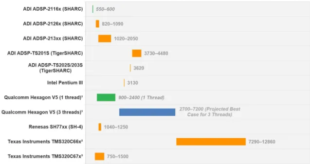
3.4 Computational Complexity . . . 22
3.5 Applications . . . 24
4 Signal Processing Platforms 26 4.1 Processor Architecture and Performance . . . 26
4.1.1 Architecture . . . 26
4.1.2 Performance . . . 30
4.2 Digital Signal Processor . . . 31
4.3 General Purpose Processor . . . 32
4.4 Platform Comparison . . . 34
4.5 Source Code Compilation . . . 36
5 Realization of the Opus Codec on x86 Platform 39
5.1 Integration . . . 39
5.1.1 Internal Opus Framework . . . 39
5.1.2 Control I/O . . . 41
5.1.3 Opus Packing . . . 43
5.1.4 Memory Allocation Requirements . . . 44
5.1.5 Opus RTP Packing . . . 46
5.1.6 Packet Loss Handling and Discontinuous Transmission . . . . 47
5.2 Compilation of the Codec . . . 48
6 Testing 49 6.1 Functional Testing . . . 49
6.2 Test Data Generation . . . 50
6.3 Performance Testing . . . 51
7 Test Results 54 7.1 Functional Test Results . . . 54
7.2 Performance Test Results . . . 54
7.2.1 Compilation Optimization Test Results . . . 54
7.2.2 Encoder Performance with Varied Parameter Conguration . . 56
7.2.3 Decoder Performance with Varied Parameter Conguration . . 57
7.2.4 Complexity Parameter Performance Test Results . . . 59
7.2.5 Performance Results of DSP . . . 61
7.2.6 Performance Evaluation and Comparison . . . 62
8 Discussion and Conclusions 65
References 67
Appendices 74
Abbreviations
A/D Analog-to-Digital
ACR Absolute Category Rating AGW Access Media Gateway ALU Arithmetic Logic Unit AMR Adaptive Multi Rate ARM Advanced RISC Machine
ATCA Advanced Telecommunications Computing Architecture ATCF Access Transfer Control Function
ATGW Access Transfer Gateway AVX Advanced Vector Extensions BDTi Berkeley Design Technology, Inc. CBR Constant Bitrate
CELT Constrained Energy Linear Transform D/A Digital-to-Analog
DSP Digital Signal Processor DTX Discontinuous Transmission EPC Evolved Packet Core
FB Fullband
FEC Forward Error Correlation FIR Finite Impulse Response FMA Fused Multiply-Add GCC Gnu Compiler Collection
GMAC Giga Multiply-and-Accumulate Operations per Second GPP General Purpose Processor
GSM Global System for Mobile Telecommunications HF High Frequency
HP High-Pass
HR Half Rate
IIR Innite Impulse Response IMS IP Multimedia Subsystem IP Internet Protocol
I/O Input/Output
iLBC Internet Low Bitrate Codec
IMDCT Inverse Modied Discrete Cosine Transform ITU International Telecommunication Union LSF Line Spectral Frequency
LTE Long Term Evolution MAC Multiply-And-Accumulate
MB Medium-band
MGC Media Gateway Controller MGW Media Gateway
MDCT Modied Discrete Cosine Transform MIMD Multiple Instruction, Multiple Data
MIPS Million Instructions Per Second MMX Multimedia Extension
MOS Mean Opinion Square
MSC Multiple Adaptive Spectral Audio Coding MTU Maximum Transmission Unit
NB Narrowband
NSQ Noise Shaping Quantization LP Linear Prediction
LPC Linear Predictive Coding LTP Long-Term Prediction OS Operating System PCM Pulse Code Modulation
POLQA Perceived Objective Listening Quality Assessment QoS Quality of Service
RCF Request for Comments
RISC Reduced Instruction Set Computer RTP Real-time Transport Protocol SDP Session Description Protocol SIMD Single Instruction, Multiple Data SIP Session Initiation Protocol
SNR Signal-To-Noise Ratio SWB Super-wideband
TCP Transmission Control Protocol TI Texas Instruments
TOC Table-of-Contents
UDP User Datagram Protocol VAD Voice Activity Detector VBR Variable Bitrate
VM Virtual Machine
VMM Virtual Machine Monitor VoIP Voice over Internet Protocol
WB Wideband
WebRTC Web Real-Time Communication WOLA Weighted Overlap-and-Add
Mobile networks have evolved rapidly from circuit switched networks of the rst generation to the latest deployments of all packet switched networks [1]. Although the main use case of transmitting speech has remained through the dierent gen-erations, the new technologies and data processing techniques have resulted in in-creasing amount of mobile applications.
Audio coding is an integral part of mobile networks. Traditionally, speech coding has been developed in parallel to high quality audio coding, as the targeted usage of the latter one has been generally more limited in terms of transmission and storing capacity, as well as computational power [2]. However, as the mobile networks have evolved, more sophisticated coding methods can be utilized to maximize the trans-mitted information's quality. On the other hand, as the coding methods improve, less capacity is needed for high quality. Consequently, there has been an eort to include high quality audio coding in mobile networks.
Another increasing trend in the mobile networks include moving the data processing to centralized data centers, so that the operators do not need dedicated hardware for network element functions [3]. An essential part of this cloudication is virtu-alization of the network elements, which essentially moves the hardware assisted processing to software built processing with generic hardware.
In this thesis, usage of a modern audio codec called Opus [4] is evaluated when it is integrated on a virtualized mobile network real-time application. It is performed by conducting a case study where the codec's integration requirements are rst spec-ied, after which it is integrated to the application. Subsequently, it is tested for functionality, as well as performance. The study aims to evaluate, how a modern high-quality audio codec performs in a virtualized network element, and how well the performance supports the cloudication when the results are reected to tradi-tional hardware performance.
The thesis is divided into seven chapters. The rst three provide the theoretical background to the topic. First, mobile networks and general audio coding theories are introduced in Chapter 2. Second, the Opus audio codec is reviewed in Chapter 3. Third, the used hardware platforms are introduced in Chapter 4. The theory is followed by three implementation related chapters. First, the realization of the codec is introduced in Chapter 5. Second, testing of the integrated codec is discussed in Chapter 6. Third, the results of these tests are presented and compared between the virtual and traditional hardware implementations in Chapter 7. The implementation is followed by discussion and conclusions (Chapter 8).
2 Background
Mobile networks are the part of communication networks that provide mobility to communications, i.e., the users do not need to be located at any xed location in order to communicate [2]. As the communication typically includes speech signal transmission, there is a need to provide as light and agile representation of speech as possible. Consequently, dierent audio compression methods (also known as audio coding methods) have been developed to serve this purpose. When these methods are combined to a framework, an entity called codec is formed.
In this chapter, a broad overview of the mobile networks is introduced with a dis-cussion of media processing in these networks. Moreover, general aspects of audio coding are presented with an emphasis on audio coding in mobile networks.
2.1 Mobile Networks
Communication networks include the services whose main purpose is to transmit information between users at dierent locations [2]. The part of communication networks that provides the ability to access the networks while not connected to the base or home network is called mobile networks. In the context of telephone networks, mobile networks are implemented as cellular telephone services [2]. They divide geographical areas into smaller cells with a radio transmission system which allow the users to communicate with each other without being physically connected via cables or wires [2]. The use of radio transmission systems introduces certain design related compromises which may result in lower quality of the transmitted signal, lower availability, and higher information security risks [2]. In the scope of this thesis, the rst one of these drawbacks is of high interest.
Communication networks can be divided into dierent types depending on how information is organized for transmission, multiplexed, routed, and switched in a network [2]. This type of division yields three main types of networks. The rst, message switched network, provides services to address, route, and forward messages [2]. The second one, circuit switched network, which is used e.g. in the traditional telephone networks, uses a dedicated end-to-end connection that is set up between the users [2]. Moreover, signaling network, which is built on top of circuit switched network, can be used to carry messages between the two ends. The third, packet switched network, divides the transmitted (digital) data into variable-length blocks, called packets, so that the data that is bigger than the packet size is segmented and transmitted in multiple packets [2].
By providing an end-to-end connection between the end-users, circuit switched net-works allow an information ow with a very low delay [2]. However, there are certain characteristics that make them unt for data transmission [2]. First, they perform optimally only with a steady information ow of voice signals, but do not support the transfer of many types of data. This is mainly due to the heavy overhead caused
by setting up a connection [2]. This overhead introduces a delay that is too long for data transmission. Second, circuit switched networks need to maintain state information on all their connections and thus an extensive list of a potentially large number of connection is needed [2]. Finally, a failure in switching a node or trans-mission line requires a set up of a totally new connection and thus causes potentially a long break in the transmission [2].
Packet switched networks are very robust against failures that may occur on the data's path [2]. This is due to their exibility to reroute the connection eciently. In addition, packet switching does not involve the need of state information, because it utilizes so called connectionless type of switching, i.e., no end-to-end connection is needed because the packets are sent separately [2]. However, connectionless trans-mission includes a requirement that every transmitted packet must contain infor-mation about itself included in the packet's header [2]. This increases the overhead which reduces the transmission capacity. Furthermore, because the packet transfer is a unreliable transfer method, mechanisms for reliable packet ordering and han-dling is needed (such as Transmission Control Protocol (TCP)) [2].
The development of mobile networks has been divided into generations each having their own specication [1]. Simply abbreviated as 1G, 2G, 3G, and 4G, each gen-eration has provided a new approach to the mobile networks reecting the newest innovations in technology at the time of the specication's deployment. 1G was the rst generation of the mobile network specications and was purely an analog circuit switched network [1]. Therefore, there is no possibility to transmit data via 1G networks. 2G started to provide data transmission by allowing digital systems as overlays or parallel to the analog ones [1]. With 2G the typical data rates vary from 100 to 400 Kbit/s. 3G started to already include dedicated digital networks in parallel to the diminishing analog ones, allowing data rates from 0.5 to 5 Mbit/s [1].
4G is the latest generation that has been already deployed [5]. Unlike the previous generations, which were explicit specications for the technology, 4G is rather a set of requirements [1]. Hence, any technology meeting these requirements can be categorized as 4G. An example of a 4G technology is Long Term Evolution (LTE) Advanced [1]. It is purely a digital and packet switched network and is based on IP (Internet Protocol). Therefore, the technological requirements are only designed for packet switching and data rates from 1 Mbit/s even up to 50 Mbit/s can be obtained [1].
As the development of these dierent generations shows, the mobile network evolu-tion is heading from the circuit switched networks towards purely packet switched ones. This allows more exibility to the applications, since all sorts of data can be transmitted via the packets and even internet applications can be developed as part of the mobile network systems.
2.1.1 Media Processing in Mobile Networks
Mobile networks divide the geological areas into cells, each of which include a radio access network (RAN) [1]. This is illustrated in Figure 1. When a connection is established, the user's mobile device connects to the RAN of the cell where they are currently located. This RAN is connected to a core network where data routing, accounting, and policy management is performed [1]. Subsequently, a connection to the destination network is established via an external carrier network, e.g., public Internet, [1] if the receiver is not within the range of the same core network [2]. The destination core network processes the connection and transmits it further to the end user via the RAN of the end user's location [1].
Figure 1: Schema of a mobile network, adopted from [1].
The packet switched core network (e.g., Evolved Packet Core (EPC) in LTE) in-cludes a specication called IP multimedia subsystem (IMS), which provides certain functions and services for processing and streaming multimedia, such as audio or video signal [6]. It was specied by the 3GPP (The 3rd Generation Partnership Project), which is a union of dierent telecommunications standard organizations [7].
IMS includes all the core network elements that are related to multimedia services. Its main purpose is to provide the operators a possibility to oer multimedia services that are based on and built upon Internet applications, services, and protocols [6]. Hence, IMS includes the functions needed in providing applications for Voice over Internet Protocol (VoIP), Voice over LTE, and other IP based applications.
When there are more than one network involved, dierent types of interworking are needed, e.g., matching their media resources [8]. An essential instance where media resource matching is needed, is the case of diering codecs, i.e., when the source
network has encoded the speech or audio stream with a codec that the destination network does not support [8]. In this case, the speech or audio stream must be rst decoded using the original codec's decoder and then encoded with a codec that is mutual to both networks so that the destination network is able to process and decode the data. This, very essential part of media resource matching, is called transcoding. E.g., when two networks' voice bearers are communicating, the media matching is provided with a function called Media Gateway (MGW) [9]. Moreover, Access Transfer Gateway (ATGW) and Access Transfer Control Function (ATCF) functions, both implemented in an element called Access Media Gateway (AGW), need to provide transcoding in certain situations [6].
In a packet switched network, data is transmitted in packets with information of themselves [2]. There are dierent ways and methods to pack data into packets, which each have their use cases. However, it is essential that the sending and receiving end have the same set of rules to pack and unpack these packets. Therefore, dierent protocols have been developed to ensure that both sides are using the same methods to handle the packets. According to Leon-Garcia and Widjaja "a protocol is a set of rules that governs how two communicating parties are to interact" [2]. Next, two common protocols in real-time speech transmission, Real-time Transport Protocol (RTP), and Session Description Protocol (SDP) are introduced. They are used for transmitting real-time audio in mobile networks, as well as setting up a voice call.
2.1.2 Real-time Transport Protocol
Real-time transport protocol provides end-to-end transport functions for real-time data transmission including, e.g., audio or video [10]. These functions include pay-load type identication, sequence numbering, timestamping, and delivery monitor-ing. Furthermore, RTP is often run on top of Unied Datagram Protocol (UDP) so that both protocols contribute to the protocol functionality, the latter one providing multiplexing and checksum services [10].
Generally, RTP data can be divided into two parts. First, "a prole denes a set of payload type codes and their mapping to payload formats (e.g., media encodings)" [10]. Furthermore, prole may also include additional information about possible modications to RTP that are specic to a certain application. Second, payload for-mat denes how the actual data, e.g. audio or video encoding, is carried in RTP. [10] A basic RTP packet consists of a 10-eld header, and a payload [10]. These elds include information about the version used, payload type, sequence number, times-tamp (which denotes the sampling instant of the rst payload octect), synchroniza-tion source identicasynchroniza-tion, and contributing source list.
2.1.3 Session Description Protocol
When a connection is established in a mobile network, certain initial information is needed to set up the connection with the right parameters. For this purpose, there are protocols to provide such information. Traditionally, Session Initiation Protocol (SIP) has been used in application-layer as a control protocol for creat-ing, modifycreat-ing, and terminating sessions [11]. However, sessions like VoIP calls, video streaming, and multimedia teleconferencing require media details, transport addresses, and other description metadata to the participants, which are not in-cluded in the SIP protocol [11]. A protocol called Session Description Protocol (SDP) provides a standard representation for such information.
SDP session description includes information about session and name purpose, time(s) the session is active, the media comprising the session, and information needed to receive those media [11]. The last one of these may include information about addresses, ports, formats, etc. Thus, information about the used codec's details may be passed as part of SDP.
2.2 Audio Coding
When transmitting voice over a communication network, the voice must be rst transformed into an electrical form after which it can be processed and transmitted further. This electrical signal, which can be either a digital or an analog audio signal, represents the acoustic waves that we hear, only presented in a dierent domain [12]. The transform procedure begins from transforming the acoustic wave rst from the acoustic domain to the electric one by using a transducer (e.g., a microphone), after which the obtained electric signal denotes the acoustic pressure wave captured at the point of the transducer [12]. The electric signal can be digitized so that it is sampled with a certain sample rate (given in Hz), i.e., the signal's value is measured every sample period [12]. Therefore, a higher sample rate produces more samples under a certain period of time compared to a lower one. The sampled values can be presented in the digital domain by quantizing to certain quantization levels that can be presented in binary form [12, p. 482]. This, the most basic form of acoustic wave's digital representation, is called pulse code modulation (PCM) [12].
For speech and audio signals the sampling frequency of the signal needs to be su-cient to contain enough information for the application's needs. Moreover, according to Nyquist's sampling theorem, the sample rate must be at least twice the highest frequency to be transmitted [13, p. 39]. As a result, the digital signal needs lots of capacity for storage or transmission. Therefore, audio compression plays a signi-cant role when transmitting voice signals over mobile networks. This means that the audio signal is encoded (compressed), transmitted, and reproduced at the receiving end [13].
There are two types of audio coding, lossless and lossy coding (also known as per-ceptual coding). The former one is dened as "an algorithm that can compress the digital audio data without any loss in quality due to a perfect reconstruction of the original signal" [14]. However, there are limitations to the compression ratio, because all the information needed for perfect reconstruction must be transmitted. Lossy coding introduces some information loss, and thus does not provide a perfect reconstruction of the signal [15]. However, higher compression ratios can be ob-tained and therefore, perceptual coding methods are more extensively used in the mobile networks. The essential goal in coding audio in the mobile networks is to nd a good ratio between the compression ratio and the loss of quality.
Audio coding combines physical models of the audio and voice signals, e.g., source-lter-modeling in linear predictive coding [13, p. 59], to traditional information coding methods. The physical representation of the signal, however, is only an ap-proximation of the perceived voice. Furthermore, the transformation from acoustic to rst electric and then to digital domain introduces distortion to the system, which cannot be necessarily modeled [12]. As a result, there is always an error between the physically modeled signal and the actual incoming signal. This has resulted in a method of transmitting the error signal, in its entirety or an approximation, along with the calculated model [16]. Moreover, better compression ratios can be obtained by lowering the resolution or the accuracy of the used physical formula, and thus lowering the correspondence of the modeled and original signals [13].
Generally, when coding information, a sequence of symbols is coded to codewords which can be presented with lower storage capacity than the original word [2, p. 753]. When the previously described physically modeled audio signal parameters are coded, as well as the potential error signal, it is possible to obtain even better compression ratios compared to purely coding the PCM signal with the same coding algorithms, because some of the irrelevant information can be discarded from the model [15].
A very common approach in audio coding is to form the modeled signal with time-frequency mapping, in which the incoming (digital) data is segmented into smaller blocks called frames after which the temporal and spectral components are analyzed on each frame [15]. In Figure 2, a general overview of an audio codec is illustrated with a block diagram.
Figure 2a presents an encoder of a generic codec that utilizes time/frequency map-ping. The input PCM signal is rst mapped in the Time/Frequency Mapping block, after which it is fed to the Quantizer and Coding block. Moreover, the input PCM signal and the output of the Time/Frequency mapping is fed to the Psychoacoustic Model block, which performs e.g., the psychoacoustic masking threshold, depending on the codec, are calculated [17]. Also this block's output is fed through the quan-tizer and coding block so that all the information can be packed into one encoded bitstream. The Frame Packing block performs this packing.
8 Time / Frequency Mapping Quantizer and Coding Frame Packing Psychoacoustic Model Encoded bitstream PCM signal (a) Frame Unpacking Reconstruction Frequency / Time Mapping
Encoded bitstream Decoded
audio signal
(b)
Figure 2: General block diagrams of a codec's encoder (a), and decoder (b), adapted from [17].
When the receiving end has received the encoded bitstream, it can be decoded back to an audio signal with a decoder illustrated in Figure 2b. First, the incoming bitstream is unpacked in the Frame Unpacking block. Second, the signal is recon-structed in the Reconstruction and Frequency/Time Mapping blocks using both, the time/frequency mapped data as well as the data obtained from the encoder's psychoacoustic model block [17]. The output of the decoder is an audio stream, which in lossless case corresponds exactly to the input of the encoder. Next, a very common audio coding method called Linear Predictive Coding is reviewed.
2.2.1 Linear Predictive Coding
A very classic speech coding method called Linear Predictive Coding (LPC) utilizes Linear Prediction (LP), which is an autoregressive modeling method [13, p. 43]. It is fundamentally based on an assumption that the signal under processing is formed as a response of an IIR lter (Innite Impulse Response). One method of nding optimal coecients for this lter is to use autocorrelation analysis as specied below
r(0) r(1) r(2) · · · r(p−1) r(1) r(0) r(1) · · · r(p−2) r(2) r(1) r(0) · · · r(p−3) ... ... ... ... ... r(p−1) r(p−2) r(p−3) · · · r(0) a(1) a(2) a(3) ... a(p) = r(1) r(2) r(3) ... r(p) , (1)
sig-nal, and a(i) denotes the lter coecients [13, p. 43]. There are also other methods to obtain the optimal lter coecients such as covariance method [18]. By inverse ltering the input signal with these coecients, a residual signal can be obtained. Speech production of a human can be presented as a simple source-lter model. The vocal tract can be approximated with a lter, through which the glottis excitation signal ows [13, p. 59]. Consequently, when denoting the vocal tract as the lter calculated in LP, LPC can be utilized to reproduce the speech signal. The excitation signal of the source-lter -model is the residual signal obtained in the LP analysis [13, p. 43].
In order to reproduce a speech signal intelligibly, all the ne harmonic structure of the vocal tract's spectrum does not need be reproduced [13, p. 44]. This can improve the computational eciency signicantly, as well as the compression ratio. The order needed for intelligible speech transmission with LPC can be reduced to 10-12 [13, p. 44].
LPC has played a very important role in audio coding from its invention. It is the core technology of several lossless codecs such as MPEG4-ALS, FLAC, and WavPack [14], and lossy codecs such as AMR (Adaptive Multi Rate) [19], GSM-HR (Half Rate) [20], and GSM-FR (Full Rate) [21]. With lossless codecs LPC can provide compression ratios up to 70 % [14], and with lossy codecs even greater. 2.2.2 Transform Coding
In transform coding, the frequency mapping is performed by using a time-to-frequency-domain transform. Generally, this approach divides the signal into spectral components [17]. Depending on the algorithm used, the resolution of this division as well as the computational complexity varies. The most common trans-forms in this coding method are the Fourier transform and the cosine transform, as well as their derivatives [17]. When a signal is represented in the frequency domain, it is convenient to evaluate if there are frequencies that are not needed in the par-ticular application and thus can be omitted. Even though some information is lost, the compression ratio is increased. When the transmission capacity is limited this is a more desired result than maintaining all the information, also the irrelevant, at the expense of compression ratio.
With transform coding, it is possible to obtain a very high-resolution frequency domain estimate of the signal [15]. However, this is at the expense of the tempo-ral characteristics. A more sophisticated method to obtain the frequency domain characteristics of the signal is to divide the signal into frequency bands (also known as subbands). This, so called subband coding or multiple adaptive spectral audio coding (MSC), is often designed to match psychoacoustic characters of a human au-ditory system and is also calculated in the psychoacoustic model block of the encoder (Figure 2a) [15]. A common subband division divides the spectral information with
a resolution of critical bands which yields the Bark scale [13]. It is closely related to human hearing mechanism, i.e., a constant change in a Bark scale corresponds to a constant change in the basilar membrane's resonance position [13, p. 111].
2.2.3 Entropy Coding
When the physical models of a signal are calculated, the obtained coecients and other parameters are coded using traditional information coding algorithms and methods. Typically, in information coding, a block of data is seen as a sequence of symbols [2, p. 753]. The main goal is to map these symbols into binary represen-tation so that the average number of bits is as low as possible. Furthermore, in the case of lossless coding, the original symbols must be able to be recovered from the encoded bitstream [2, p. 753]. The best performance in coding, in terms of how many bits were needed to represent the original symbol, can be obtained by using an entropy function [2, p. 757]. A coding method called entropy coding utilizes this function, which depends on the probabilities of the sequences of the symbols. If a sequence of symbols is given as 1,2,3, ..., K and the respective probabilities to
their occurrence asP[1], P[2], P[3], ..., P[K], and these probabilities are statistically
independent, the entropy function is dened as follows
H =−
K
X
k=1
P[k] log2(P[k])
=−P[1] log2(P[1])−P[2] log2(P[2])−...−P[K] log2(P[K]), (2)
in which H stands for the entropy [2, p. 757].
There are two approaches in entropy coding depending on how the coded informa-tion is arranged into codewords. One of them utilizes Human coding and the other arithmetic coding [22]. The former one of these is a non-adaptive method, i.e., the values can be read from a table and no other values need to be coded in order to obtain a certain value at an arbitrary index of the table. However, Human coding is rather limited in the amount of compression it can provide [23]. In addition, it can only provide an integer number of bits and thus in the case where the given bits for coding is fractional, there is a redundancy of dierence between the rounded up number of bits and the fractional value of the bits [22].
Arithmetic coding is based on a presumption that the data is organized in vectors [22]. As a result, in order to be able to decode one symbol from the vector, all the previous symbols must be decoded rst. This results in a highly serial operation and increases computational complexity. However, with arithmetic coding, it is possible to obtain fractional allocation of bits per sample and thus no redundancy due to rounding is introduced [22].
2.3 Audio Coding in Mobile Networks
When the whole auditory bandwidth is included in the coding, such as in MP3 and Vorbis codecs, high qualities can be obtained [24]. However, they typically intro-duce a long algorithmic delay and thus cannot be used in real time applications. The mobile networks have always been limited by the transmission capacity [25]. There-fore, the audio coding technologies in mobile networks have traditionally limited the transmitted information, e.g., in terms of bandwidth, to gain better compression rations. As a result, these technologies introduce a low algorithmic delay with high compression ratios. The bandwidth needed for intelligible speech transmission can be limited to 4 kHz, which yields a commonly used sample rate in speech applica-tions of 8 kHz [2, 26]. However, through the evolution higher bandwidths, such as 8 kHz (with 16 kHz sample rate) [27], have been also introduced in this context. The speech coding technologies have been developed by dierent groups and organi-zations to provide codecs that utilize the constantly developing computation, stor-ing, and transmission technologies. Organizations such as 3GPP, ITU (International Telecommunication Union), and GSM (Global System for Mobile Communications) have developed speech codecs solely for mobile networks. These codecs include for instance AMR by 3GPP [19], GSM-HR and GSM-FR by GSM [20, 21], and G-series codecs by ITU [28, 29].
In parallel, as the VoIP technology has become more common, internet speech codecs have been developed by organizations such as Xiph.Org Foundation [30], Skype Technologies [31], and Global IP Solutions (currently owned by Google Inc.) [32]. The rst one of these has developed internet codecs such as Speex [33], CELT (Constrained Energy Lapped Transform) [34], and Opus [4]. The second one has developed the SILK codec mainly targeted for the web call application Skype [35]. The last one of these is the developer of iLBC (Internet Low Bitrate Codec), which is also a VoIP codec [36].
As was discussed earlier, the transmission capacity of the mobile networks has im-proved signicantly through the evolution of the newer mobile network generations [1]. Furthermore, the newest audio coding technologies, such as CELT [4, 24], have enabled the use high-quality full auditory bandwidth coding in real-time commu-nication applications by providing low enough algorithmic delay. As a result, the distinction between the two dierent coding approaches is diminishing. On the other hand, as the mobile networks are increasingly becoming all packet switched networks, the VoIP applications are also included in mobile communications in addi-tion to the native audio transmission. Hence, also the codec development branches, for internet and mobile applications separately, are gradually converging.
The distinction that remains between the VoIP and native voice communication within the mobile networks is the way the data is transmitted, i.e., VoIP utilizes the IP as is, whereas the native audio transmission in mobile networks is based on the
protocols specied for mobile networks [37]. Furthermore, VoIP does not include quality of service (QoS), e.g., packet loss handling, delay handling, and delay varia-tions handling, which introduces a need of additional processing when transmitting VoIP in mobile networks [38]. These distinctions do not aect on the audio coding algorithms as the encoded bitstream is transmitted within the payload regardless of the means of transmission.
The latest mobile audio coding development eorts incorporate the full bandwidth coding and low algorithmic delay needed in the mobile applications [24, 4]. The state-of-art real-time codec is currently a hybrid VoIP codec called Opus, providing versatility and a wide set of parameter settings. In the following chapter, Opus codec is introduced with an in-depth review on the technology behind the codec.
3 Opus Audio Codec
In this chapter a modern hybrid codec called Opus is reviewed. First, an overview of the codec is introduced with a high-level description of the features provided. Second, the dierent components, of which Opus consists of, are discussed more in detail. Finally, at the end of this chapter computational complexity is evaluated, and possible applications of the Opus are reviewed.
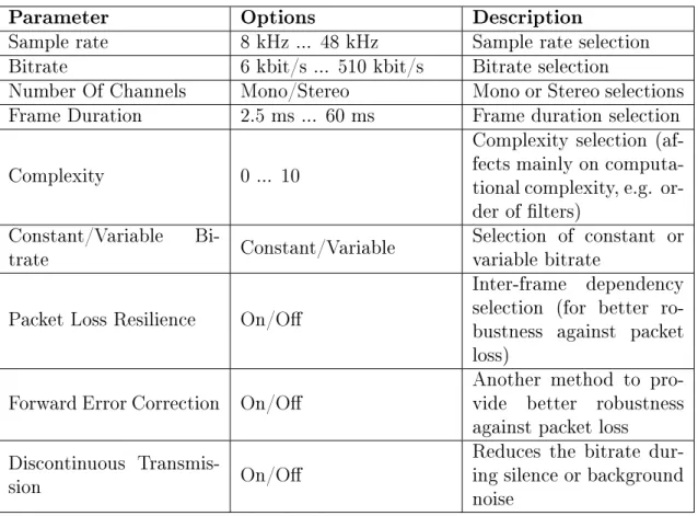
The Opus codec combines two existing coding technologies, SILK and CELT, and was originally developed to full a wide range of requirements from low bitrate tele-phony to stereo full bandwidth real-time teleconferencing [39]. To be able to provide such a wide range of features, the codec needs to be very versatile and congurable. This yields a large set of parameters that can be congured depending on the ap-plication used. The available parameters in the Opus codec are presented in Table 2. Table 2: List of available conguration parameters of Opus audio codec, adapted from [4].
Parameter Options Description
Sample rate 8 kHz ... 48 kHz Sample rate selection Bitrate 6 kbit/s ... 510 kbit/s Bitrate selection
Number Of Channels Mono/Stereo Mono or Stereo selections Frame Duration 2.5 ms ... 60 ms Frame duration selection
Complexity 0 ... 10
Complexity selection (af-fects mainly on computa-tional complexity, e.g. or-der of lters)
Constant/Variable
Bi-trate Constant/Variable Selection of constant orvariable bitrate Packet Loss Resilience On/O
Inter-frame dependency selection (for better ro-bustness against packet loss)
Forward Error Correction On/O Another method to pro-vide better robustness against packet loss
Discontinuous
Transmis-sion On/O
Reduces the bitrate dur-ing silence or background noise
The rst parameter in the table is sample rate. Opus codec provides a selection of sample rates from 8 kHz to 48 kHz, with several sample rates in between. In Table 3 these sample rates are presented, and their corresponding audio bandwidths are introduced, as they are used later in this thesis. Super-wideband used in the
Opus is dened as 24 kHz, even though the same name is used in other audio coding standards for 32 kHz sample rate. This is mainly because it is more convenient for Opus' internal processing [4].
Table 3: Supported samplerates in the Opus codec, adapted from [4].
Sample rate Name Abbreviation
8 kHz Narrowband NB
12 kHz Medium-band MB
16 kHz Wideband WB
24 kHz Super-wideband SWB
48 kHz Fullband FB
The second parameter, bitrate, denotes how many bits are used to represent one second of data in the coded domain [40]. Thus, the storage and transmission capac-ity is directly proportional to it. The Opus codec supports any bitrate in the range of 6 kbit/s to 510 kbit/s. Furthermore, there are recommendations of the optimal bitrates depending on the used sample rate [4].
Frame duration selection in the Opus oers several alternatives for the frame length. The available frame lengths are 2.5 ms, 5 ms, 10 ms, 20 ms, 40 ms, and 60 ms [4]. Complexity selection aects the computational complexity of certain parts of the coding. E.g., order of certain lters can be reduced with this parameter [4]. How-ever, lower complexity results in lower quality because the complexity is reduced by lowering the accuracy.
Constant/variable bitrate selection provides an option to choose between constant bitrate (CBR), and variable bitrate (VBR). The former one of these uses the same bitrate throughout the audio data, whereas the latter one varies the bitrate to nd the optimal value for the data processed at all times [4]. VBR also results in better coding eciency [40].
Audio codecs are often designed to use the inter-frame correlations in order to re-duce the bitrate [4]. Therefore, when a packet is lost, the decoder needs to receive several packets before it is able to eectively reconstruct the signal. Forward Error Correction (FEC) can be used to improve the robustness against packet loss caused by this problem. In addition, Packet Loss Concealment (PLC), can be utilized us-ing the algorithms provided within the codec for improved robustness against packet loss. It attenuates the signal slowly based on the previous frames, and additionally generates conform noise [41]. Consequently, a sudden gap in the audio stream is avoided when packet is occasionally lost.
Discontinuous Transmisson (DTX) is part of the SILK's functionality and it reduces the transmission bitrate when the signal is silent or there is only background noise
present [41]. In fact, when DTX is used and silence is detected, only one frame every 400 ms is transmitted. The packet loss concealment functionality is invoked when no data is transmitted due to DTX, so that the indicated silence does not result in total silence at the receiving side [41].
In addition to the previously introduced parameters, there are three dierent appli-cation selections that result in dierent coding paths within the codec [42]. First, VoIP application aims at best quality for speech signals by emphasizing formants and harmonics. Second, Audio selection results in best quality for non-speech signals such as music or combined speech and music signals. Third, Restricted Low-Delay mode provides slightly reduced algorithmic delay, but also disables the speech en-hancements.
Being a hybrid codec, Opus provides three dierent modes of coding. Purely either CELT or SILK codec, or a hybrid mode which combines these two [39]. The usage of these layers is automatically toggled depending on the parameter set. Next, the SILK codec is reviewed more in detailed level. It is followed by a detailed description of the CELT codec, after which the way these two codecs are combined into the Opus is discussed.
3.1 SILK
SILK codec is a speech codec developed by Skype [35] and is based on traditional speech coding techniques like LPC and LTP (Long-Term Prediction, also derived from LP) [43]. Similarly to Opus codec's development, SILK was developed to meet the needs of VoIP applications. With a support for four dierent samplerates 8 kHz, 12 kHz, 16 kHz, and 24 kHz [44], it is a highly scalable codec. Furthermore, changeable bitrate and complexity parameters provide exibility to meet the used application the best [35]. Also features such as DTX and VBR are supported [44]. The two linear prediction based coding methods (LPC and LTP) used in SILK are divided so that LPC is used every 20 ms to model the vocal tract transfer function, and LTP every 5 ms to model the long-term correlation of pitch harmonics in the voiced speech signal [43]. The block diagram of a SILK encoder is illustrated in Figure 3.
As the block diagram shows, encoding begins with feeding the input signal through a high-pass lter (HP), as well as voice activity detector (VAD). The former is a 2nd order adaptive IIR lter with a cuto frequency between fc = 60 Hz ... 100
Hz, and its main function is to lter the low-frequency background and breathing noises [45]. VAD measures the speech activity level by combining the SNRs (signal-to-noise ratios) of four separate frequency bands [45]. The HP lter is dependent on the detected voice activity level so that the SNR of the lowest frequency band of the VAD, and the smoothed pitch frequencies found in the pitch analysis, aect on its cuto frequency. As a result, high pitched voices have a higher cuto frequency.
Figure 3: Block diagram of a SILK encoder, adopted from [45].
After determining the voice activity level and ltering the input signal, the pitch of the voice is analyzed in the Pitch Analysis block. It is performed to a pre-whitened signal (pre-whitening is performed within the block) which is decimated into two dierent signals with 8 kHz and 4 kHz sample rates [45]. The fundamental fre-quency is found through autocorrelation analysis so that it is performed rst to the signal with 4 kHz sample rate for less accurate estimation, and then to the signal with 8 kHz signal for more precise estimation [45]. The nal pitch is determined by analyzing the original, not decimated signal with an integer valued pitch lag search around the previously obtained estimate. Subsequently, each lag is evaluated with a pitch contour from a codebook [45]. The found pitch is fed directly to the range encoder, and encoded as part of the bitstream.
In addition to pitch calculation, also the signal classication for the frame under analysis is determined in the pitch analysis block. The result of the autocorrelation analysis is compared to a certain threshold, so that if the autocorrelation result is lower than the threshold, the signal is classied as unvoiced speech [45]. The threshold is calculated from a weighted combination of the signal classication of the previous frame, speech activity level, and the slope of the SNR obtained in the VAD with the corresponding frequency [45].
The actual linear prediction is performed in the Prediction Analysis Block with the previously analyzed signal classication taken into account. For voiced speech, LTP is used with the pre-whitened input signal incoming from the pitch analysis block [45]. The LTP-coecients are estimated with covariance method [18] from every 5 ms subframe. The residual signal is determined by ltering the non-whitened input signal with the LTP-lter.
The short-term prediction coecients are calculated from the LTP-analysis' resid-ual signal with the traditional LPC-analysis [45]. However, instead of determining the LP-coecients with autocorrelation or covariance method, they are computed by using the novel implementation of Burg's method [46]. Therefore, stable lter coecients are obtained eciently and the computational complexity is reduced remarkably [45, 46]. Calculating the LPC-coecients from the LTP-signal results in more prediction gain and consequently, lower bitrate can be used. For unvoiced signal, LPC is performed directly to the non-whitened input signal.
All the LPC-coecients are transformed into Line Spectral Frequencies (LSFs), which provide an alternate and more ecient representation of these coecients for speech coding and transmission [47]. Subsequently, these frequencies are quan-tized, and used to re-calculate the LPC residual signal so that also the quantization error of LSFs is taken into account when reproducing the signal [45].
SILK uses noise shaping to make the quantization noise less audible to human au-ditory system by performing weighting ltering when encoding [45]. Therefore, no weighting ltering is needed when decoding and thus, no side information about the lter needs to be sent along with the encoded bitstream. The noise shaping is performed in the encoder's noise shaping analysis, gain quantization, and predictive noise shaping quantization blocks (in Figure 3).
Predictive Noise Shaping Quantization (NSQ) block also generates the residual sig-nal from the previously determined LTP- and LPC-coecients [45]. This excitation signal is subsequently quantized into an integer-valued signal, which is entropy coded in blocks of 16 samples in the range encoder. The remaining LSF Quantization block quantizes the line spectral frequencies with vector quantization using codebook vec-tors and scalar inter-LSF prediction [45]. The quantized signal is entropy coded with the range coder which outputs data with variable bitrate [45].
The encoded bitstream can be decoded back to an audio signal with a decoder. The decoder side LP functionality is illustrated in Figure 4. It performs the inverse op-eration to the encoder's essential blocks and consists of excitation generator and the predictive ltering of the LTP and LPC synthesis lters. The rst one of these gen-erates the excitation signal for the LTP synthesis lter from the quantization indices transmitted from the encoder. The LTP synthesis is performed as was described in Section 2.2 for linear predictive coding. The LPC synthesis lter is in series with the LTP and thus the output of the LTP denotes the LPC excitation signal.
3.2 Constrained Energy Lapped Transform
Constrained Energy Lapped Transform is a transform coding technology developed by Xiph.Org, and is based on the Modied Discrete Cosine Transform (MDCT) [48]. The fundamental idea behind the codec is to preserve the spectral envelope of
Figure 4: Block diagram of a SILK decoder's LP functionality, adopted from [45]. the input [24]. Moreover, CELT was designed to support also higher sample rate applications up to 48 kHz, and bitrates from 32 kbit/s to 128 kbit/s [49]. One of the key features in CELT is to use the transform with very short windows so that the algorithmic delay is minimized [48]. The development with CELT started from same principles as with Opus codec, to have a framework that is highly scalable and versatile. Subsequently, the development of CELT was merged to Opus [49] and hence the technology behind is being developed with the Opus instead of a separate codec.
There are four principle elements behind the CELT algorithm [24]. First, the MDCT output is divided into bands, referred as energy bands, that approximately corre-spond to the Bark scale. This improves the perceived quality as the band division corresponds to the resolution of the auditory system. The comparison between the CELT energy band division and bark-scale is illustrated in Figure 5. As can be seen in the gure, at the higher frequencies the codec's energy bands correlate highly with the Bark scale. However, at the spectrum's lower end this correspondence is not as high due to MDCT's lower resolution at the low frequencies [24].
CELT Bark
Figure 5: Comparison of CELT energy bands and Bark scale, adapted from [48]. Second, the encoder codes each band's energy separately with the decoder ensur-ing that the output's energy corresponds these energies [24]. Third, the normalized spectrum of each band is constrained so that they have unit norm through the whole algorithm [24]. Fourth, a long-term predictor is used for coding pitches and is en-coded as a time oset, yet encoding the gain of the pitch in the frequency domain [24].
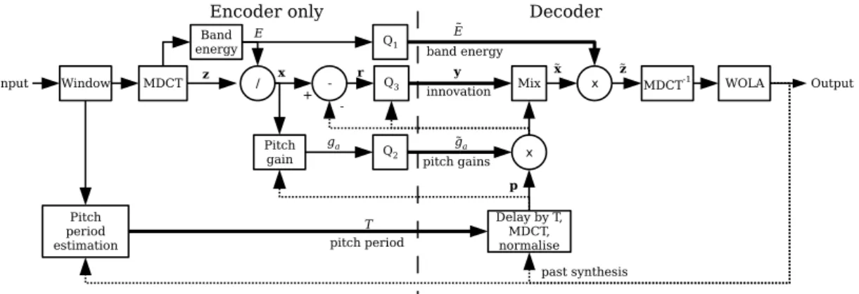
Figure 6 represents the block diagram of the CELT codec, with both encoder and decoder presented. The rst block, Window, performs windowing to each frame [48] using at-top MDCT windows with 2.5 ms overlap between the frames. For the overlapping parts, Vorbis power-complementary window (as is specied in [50]) is used, which is also used in the decoder side when performing the weighted overlap-and-add (WOLA) synthesis. The MDCT block performs the modied discrete cosine transform so that the computed MDCT spectrum is divided into the energy bands as was presented in Figure 5 [24]. Each band is normalized separately and transmitted to the decoder through a quantization block, Q1.
Figure 6: Block diagram of a CELT codec, adopted from [24].
Pitch prediction is used to model high-frequency information such as closely-spaced harmonics of speech or solo instruments [24]. The determined pitch's gain is com-puted and normalized to unity. As a result, the pitch can be applied in the frequency domain to avoid the weakening of the pitch harmonics at high frequencies. In ad-dition, xed and adaptive codebooks are combined in the encoder's quantization blocks where entropy coding is applied [24]. However, the xed codebook gains do not need to be transmitted because the computation can be deduced to a rather simple form and it can be calculated when decoding. The codebook contribution is regarded as innovation in Figure 6.
There are altogether three dierent quantizers in the CELT encoder (Q1, Q2, and
Q3 in Figure 6). The rst, Q1, quantizes the band energies, the second, Q2, the pitch gains, and the third, Q3, the innovation. For all quantizers, entropy coding is used to allocate the fractional number of bits to integers. For bit allocation, two of the transmitted parameters are encoded with a variable bitrate [24]: the entropy-coded energy of each band and the pitch period. However, when constant bitrate is needed the innovation quantization can be adapted to compensate the variability of the previous two parameter sets [24]. Additionally, to minimize the amount of used bits, it is assumed that certain parameters are known for both encoder and decoder, and do not need to be transmitted [24]. E.g., the number of octets (8-bit bytes) used to encode the frame is assumed to be shared information.
Occasionally, transform-based codecs introduce pre-echo to the signal due to the quantization error that is spread through the window, including the transient events [51]. Generally, this does not aect CELT because the frame sizes are small. How-ever, in certain extreme cases it may occur, and therefore CELT uses a detector to detect the transients [51]. In the case a of transient, the frame is split into two shorter half-frames, to which the MDCTs are applied. The outputs are then inter-leaved yielding a situation where the rest of the codec is not aected.
3.3 Opus Codec
The Opus codec combines the two previously presented coding technologies, SILK and CELT, into a single codec. It can be used either in a hybrid mode where it uses both of them, or only with either of the two codecs [4]. However, in addition to simply combining these two codecs into one framework, certain changes have been made in order to improve the quality, to t them better together, and to reduce the psychoacoustic artifacts of the two codecs [48].
3.3.1 Combination of the Two Coding Technologies
As the Opus combines the SILK and CELT technologies, they are separated to serve dierent purposes. When using either of the original codec modes alone, SILK can be operated with up to 16 kHz samplerate, and CELT up to 48 kHz [4]. Thus, according to the naming convention introduced in Table 3, SILK supports NB, MB, and WB, whereas CELT supports all the sample rates from NB to FB. For the frame lengths, SILK supports 10 ms ... 60 ms, and CELT supports 2.5 ms ... 20 ms. As a result, SWB and FB data cannot be coded with higher frame lengths than 20 ms and therefore data containing longer frames is split into more appropriate frame lengths for the CELT.
In the hybrid mode of the Opus codec, the operation is divided so that the crossover sample rate is 16 kHz [4]. In other words, the input signal is divided into the two coding paths, in which it is decimated to 16 kHz sample rate for SILK, and for CELT the frequencies below WB are discarded. With this conguration, Opus is able to provide hybrid mode operation at SWB and FB. Due to the dierent look-ahead times between these two codecs (CELT having shorter) a delay of 4 ms is introduced to the CELT coding path. However, when using only CELT the additional delay is omitted. An overview block diagram of the Opus codec is illustrated in Figure 7. As can be seen in Figure 7, the coding is divided into two branches. In the encoder, the higher branch represents the input of the CELT-encoder, and is delayed in the D block to match the dierent look-ahead times. The lower one represents the input of the SILK-signal, which is decimated so that only lower frequencies are encoded with the SILK layer. After encoding them in their respective encoders, the two
ff
ff
ff
Figure 7: Block diagram of Opus codec, adopted from [48].
encoded signals are multiplexed, i.e., multiple signals combined into one signal or bitstream in the digital domain [2], and transmitted. In the decoder, the bitstream is demultiplexed and the two separate, CELT and SILK, signals are then decoded in their respective decoders. A sample rate conversion is performed to the output of the SILK-decoder to match the desired output sample rate. Finally, the two coding branches are summed together so that the output of the Opus decoder is obtained. Opus uses also additional internal framing to allow the packing of multiple frames into a single packet [48]. Moreover, the mode, frame size, audio bandwidth, and channel count are signaled in-band, and are encoded in a table-of-contents (TOC) byte. These are not entropy coded, an therefore it is easy for the external ap-plications to "access the conguration, split packets into individual frames, and recombine them" [48].
When changing the conguration so that the CELT mode is used before and after the change, the overlap of the transform window is used to avoid discontinuities [48]. However, when a change between CELT and SILK or the hybrid mode occurs, there is a mismatch between the domains where the computation is performed, the former one utilizing frequency- and the latter one time-domain algorithms. Therefore, in this type of change in modes, an additional 5 ms redundant CELT frame is included to the bitstream. Furthermore, in this case decoder uses overlap-add to bridge and gap between the discontinuous data, which smooths the changes between the dier-ent modes [48].
3.3.2 Modications to the Two Coding Technologies
The SILK codec has been an individual project and thus is used in the Opus codec almost as is. The originally supported sample rate of 24 kHz was not included when SILK was integrated into the Opus codec [4]. CELT, however, was merged to the Opus project [49] and therefore modications to the originally proposed version [24, 51] have emerged through the development of Opus.
CELT introduces a drawback when using the low overlap window by increasing spec-tral leakage which is especially problematic for highly tonal signals [48]. Therefore, in the Opus a pre-emphasis rst-order low-pass FIR lter (Finite Impulse Response) is introduced in the encoder side. Respectively, the corresponding inverse operation with a de-emphasis lter is applied when decoding. As a result, lower frequencies are attenuated, and therefore do not cause leakage at the higher frequencies. In ad-dition, a perceptual pitch enhancing prelter and postlter pair is used to address the same problem [48].
Depending on the signal, some frames may contain both transients and tonal infor-mation. Consequently, these frames require good frequency resolution in addition to good time resolution [48]. Therefore, the Opus utilizes a selective modication of the time-frequency resolution so that it includes a good resolution for low-frequency tonality, but also a good time resolution for transients' high frequencies. The time-frequency resolution is improved by computing multiple short MDCTs [48]. This, however, decreases the frequency resolution, and therefore the Hadamard transform is used to the transform coecients across the computed multiple short MDCTs [48]. With transform based codecs, such as CELT, tonal-noise may be introduced [48]. This is due to the quantization in which a large number of HF coecients get rounded to zero, and thus the remaining non-zero coecients may sound tonal. To address this problem Opus applies spreading rotations that spread the transform coecients dynamically over multiple frequencies [48, 52]. When decoding, an in-verse operation can be applied to obtain the original transform coecients [48]. When transients are encoded with low bitrates, it may happen that all the coe-cients of a short MDCT are quantized to zero [48]. This causes audible drop outs, even when the energy of the entire band would be preserved. The Opus codec de-tects such holes and lls them with pseudo-random noise at the same level as the minimum of the two previous bands' energy levels [48].
Entropy coding is used extensively in the SILK- and CELT-codec, and consequently also in the Opus codec [45, 48]. In the context of Opus, all the entropy coding is performed with a range coder which is an arithmetic coder and which outputs 8 bits at a time [24]. The main reason for using arithmetic coding is its ability to accept fractional bits and provide better compression ratios [22].
3.4 Computational Complexity
Both SILK and CELT were designed for real-time applications and thus need be computationally simple enough to reduce the algorithmic delay to sucient limits [31, 34]. The former one of these uses the time-domain techniques for coding (LPC and LTP) and its original target was speech coding. At the frequency spectrum's low end, where most of the essential speech information is, these techniques are
com-putationally ecient [4]. At the high end of the spectrum, however, the transform based techniques are more ecient and thus combining these two into one hybrid codec is an eort to maintain the maximum eciency [4]. Furthermore, when com-bining the most ecient parts of the two codecs, the combination may operate even more eciently than the original codecs individually.
Generally, transform and subband coding techniques, such as MDCT in CELT, are limited by their coding eciency [53], because the transform itself is computationally demanding operation [54]. MDCT transform is dened as follows
X[k] = NX−1 n=0 x[n]·cos(2n+ 1 + N 2)(2k+ 1)π 2N , (3)
where X[k] is the transformed signal, x[n] is the input signal, n = 0, ..., N − 1
and k = 0, ..., N/2−1, N is the window length [54]. As Equation 3 shows, there
is a sum of products between the input sample and a cosine term over the entire window. Therefore, every time MDCT is computed the whole window needs to be iterated through. As a result, MDCT introduces always an algorithmic delay that corresponds to the number of iterations [55]. The inverse MDCT (IMDCT) is applied to the half of the window length and thus the delay caused by IMDCT is half of the corresponding MDCT [54]. IMDCT is dened as
x[n] = N/X2−1 k=0 X[k]·cos(2n+ 1 + N 2)(2k+ 1)π 2N , (4)
in which x[n] is the reconstructed signal, X[k] is the MDCT transformed signal,
k = 0...N/2−1, and n = 0, ..., N −1 [54]. Similarly to the MDCT, also IMDCT
introduces an algorithmic delay, as it includes iteration through the coecients. The algorithmic delay caused by the iterations, shown in Equations 3 and 4, can be only reduced by minimizing the number of iterations. This number depends on the frame size, as the processing is done for one frame at the time. To address this issue, CELT uses a very short frame length to minimize the delay [51].
The range coder that performs the entropy coding is an arithmetic coder, which minimizes the used bits for coding. This may introduce computational complexity to the decoder side, as the coded vector needs to be decoded and iterated through
N −1 times, if a specic value with an index N needs to be decoded. However,
as could be seen in the SILK and CELT codecs' block diagrams (Figures 4 and 6), the arithmetic decoder is applied only in the beginning of the decoding procedure. Therefore, when the actual audio decoding is performed, all the data is already ac-cessible and no range decoding is needed to obtain single symbols from the bitstream. Opus' computational complexity can be modied with the complexity parameter, as introduced in Table 2. It adjusts the order of certain lters, the number of states in
the residual signal quantization, and the use of certain bitstream features including variable time-frequency resolution and the pitch post-lter [4]. The rst one of these, ltering (all the IIR- and FIR-lters), is performed by convolving the input signal with the impulse response of the lter [56]. Convolution integral in discrete domain is dened as a sum of products of the lter coecients, and current and old samples. This is shown below in Equation 5
y[n] =x[n]∗h[n] =
n
X
k=0
x[n]·h[n−k], (5)
in whichy[n]is the convolution result,x[n]is the input signal, andh[n]is the lter's
impulse response [56]. As can be seen in the equation, also ltering is an iterative process. The number of these iterations is directly proportional to the lter's order. Therefore, adjusting the order of the lter can result in lower complexity of the algorithm.
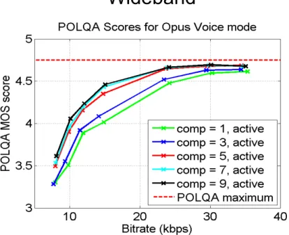
When the complexity of the algorithm is reduced, the quality is also reduced [4]. Figure 8 illustrates how the complexity parameter aects the voice quality of the codec with dierent bitrates. In the gure, objective voice quality results for WB signal is presented. X-axis denotes the bitrate in kbit/s, and y-axis denotes the MOS (Mean Opinion Square) score measured with POLQA (Perceptual Objective Listening Quality Assessment) measurement methods specied by ITU-T [57]. The voice quality measured with this method compares the original input PCM and the decoded output PCM together in a psychoacoustic model [57]. The comparison re-sults are subsequently mapped to the MOS values that are common to the ACR (Absolute Category Rating) specied in the ITU-T recommendation P.800 [58]. As Figure 8 shows, the calculated MOS scores vary more with the lower bitrates compared to higher. However, they do not dier remarkably with the complexity values above 5. In other words, the complexity does not aect the sound quality sig-nicantly above this limit. Also other bandwidths show similar results, as presented in the [59].
3.5 Applications
The Opus codec was originally developed for interactive Internet applications [48]. Applications such as Skype and WebRTC (Web Real-Time Communication) are both based on VoIP, i.e., the encoded speech is digitized in voice packets and trans-mitted via Internet Protocol (IP) [60]. The former one of these is a peer-to-peer application, in which the connection is established between the two end users (peers) directly, and thus the application is processed on the peer's own hardware [61]. The latter one, provides an Application Programming Interface (API) so that developers can write rich, real-time multimedia applications on the web, i.e., the application is run within a browser and no external plug-ins or installable software is needed [62]. However, the actual processing is still performed on the user's hardware.
/
Figure 8: Speech quality with dierent complexities and bitrates measured for WB data with POLQA, adopted from [59].
The application to which the codec was integrated in this thesis was an IMS network element. This provides functionality for matching dierent codecs of two commu-nicating networks. E.g., when a VoIP call is transcoded to use network's native codecs, the network element's hardware is used for matching the diering codecs. The basic VoIP applications presented in this section are based on performing the processing on the end user's hardware. Therefore, they are not completely compa-rable to the processing performed in the IMS functions such as MGW, in which one piece of hardware is designed to perform the data processing for as many instances as there is capacity. This sets certain requirements to the computational eciency of the application, and also to the hardware used for the processing. The latter one is discussed more in detail in Chapter 4.
4 Signal Processing Platforms
The network elements that provide signal processing functions, such as MGW, have been traditionally implemented on dedicated hardware (e.g. on an ATCA platform (Advanced Telecommunications Computing Architecture, [63])) to provide the re-quired computational performance [64]. The piece of hardware that performs the actual calculative signal processing algorithm processes is called a processor. For digital signal processing, a customized processor called Digital Signal Processor (DSP) has been generally used due to its ability to perform signal processing tasks eectively [65]. However, as the general purpose processors (GPP) have developed, their usage has become more reasonable also in digital signal processing. As a re-sult, there has been an eort to move digital signal processing applications to more generic hardware, such as servers, so that no dedicated hardware is needed [3, 66]. This way, the signal processing tasks can be performed natively on the hardware, or within a virtual machine (VM) that is run on the server. The latter option en-ables one server to provide multiple VM instances and thus provide an eective way to share resources of one piece of hardware [67, p. 525]. Moreover, because the hardware is generic, there is no need for designing dedicated hardware and thus the product's development costs are decreased [3].
In this chapter, the signal processing platforms used in the network elements are reviewed. First, a generic overview of a processor is introduced by observing the common features that all the processors share. Second, both the DSP and GPP are introduced more in detail, after which they are compared in terms of performance. Third, the compilation of the source code to machine language is discussed, as it aects the performance of an application. Finally, the concept of a virtual machine is reviewed as it introduces certain dierences compared to the native processing on the same hardware.
4.1 Processor Architecture and Performance
When choosing a processor for an application several performance related aspects need to be taken into consideration. On one hand, the computational speed may aect the choice when the processing times need to be reduced. On the other hand, if the application is part of mobile hardware with an external energy source (e.g., battery), the power related performance needs to be sucient. In the scope of this thesis, mainly the execution speed related performance is discussed. Architecture is one key factor in processor's performance. There are many dierent types of pro-cessors that each serve dierent purposes. In the following section, general aspects of a processor architecture are discussed.
4.1.1 Architecture
When processing is performed on a processor, it ows through a certain path. This is called a data path, and along it the arithmetic operations of the processor are
![Figure 1: Schema of a mobile network, adopted from [1].](https://thumb-ap.123doks.com/thumbv2/123dok/2220305.2718527/12.892.159.781.377.676/figure-schema-mobile-network-adopted.webp)
![Figure 2: General block diagrams of a codec's encoder (a), and decoder (b), adapted from [17].](https://thumb-ap.123doks.com/thumbv2/123dok/2220305.2718527/16.892.151.781.107.444/figure-general-block-diagrams-codec-encoder-decoder-adapted.webp)
![Table 3: Supported samplerates in the Opus codec, adapted from [4].](https://thumb-ap.123doks.com/thumbv2/123dok/2220305.2718527/22.892.273.657.240.396/table-supported-samplerates-opus-codec-adapted.webp)
![Figure 3: Block diagram of a SILK encoder, adopted from [45].](https://thumb-ap.123doks.com/thumbv2/123dok/2220305.2718527/24.892.184.753.117.373/figure-block-diagram-silk-encoder-adopted.webp)
![Figure 5: Comparison of CELT energy bands and Bark scale, adapted from [48].](https://thumb-ap.123doks.com/thumbv2/123dok/2220305.2718527/26.892.160.783.725.879/figure-comparison-celt-energy-bands-bark-scale-adapted.webp)
![Figure 9: Example of a pipeline, adopted from [67].](https://thumb-ap.123doks.com/thumbv2/123dok/2220305.2718527/36.892.163.778.113.493/figure-example-of-a-pipeline-adopted-from.webp)