Evaluation of Models for Estimating Shrinkage Stress in Patch Repair
System
Stefanus A. Kristiawan*
(Received August 23, 2012, Accepted November 2, 2012)
Abstract: Cracking of repair material due to restraint of shrinkage could hinder the intended extension of serviceability of repaired concrete structure. The availability of model to predict shrinkage stress under restraint condition will be useful to assess whether repair material with particular deformation properties is resistance to cracking or not. The accuracy in the prediction will depend upon reliability of the model, input parameters, testing methods used to characterize the input parameters, etc. This paper reviews a variety of models to predict shrinkage stress in patch repair system. Effect of creep and composite action to release shrinkage stress in the patch repair system are quantified and discussed. Accuracy of the models is examined by comparing predicted and measured shrinkage stress. Simplified model to estimate shrinkage stress is proposed which requires only shrinkage property of repair material as an input parameter.
Keywords:cracking, prediction model, repair, restraint, shrinkage stress, simplified model.
1. Introduction
Spalling of concrete cover is an indication of degradation that could impair the performance of reinforced concrete structure in service. This type of damage could be due to reinforcement corrosion or other causes. Patch repair is a common method to recover the size and appearance of this damaged concrete, protect the exposed reinforcement from further corrosion and partially regain its structural capacity. The effectiveness of this repair method to restore damaged reinforced concrete is controlled by the performance and durability of the patch repair material being used.
Matthews (2007) investigated performance of repair materials via case histories and found a variety of modes of repair failure. The principle modes of repair failure were cracking (32 %), debonding (25 %), continued corrosion of embedded reinforcement (22 %), alkali aggregate reaction (4 %) and others (17 %). In term of cracking, this mode of repair failure could be triggered by restraint of drying shrinkage. As repair material is applied on top of damaged concrete, they turn into composite system. The new repair material will shrink considerably while the shrinkage of the substrate concrete is negligible. This differential shrinkage creates restraint to the deformation of repair material. In turn, tensile stress is induced in the repair material. If the induced
tensile stress (termed as shrinkage stress) exceed tensile capacity of repair material, it will cause cracking in the repair material.
Assessment of repair material performance related to shrinkage cracking has been suggested in literatures and may be categorized into three methods. The first method is to limit the magnitude of shrinkage as a criterion to determine the cracking tendency of repair material. The basis of this method is an assumption that material with a higher shrinkage property should have a higher risk of cracking and vice versa. Limita-tion of magnitude of shrinkage has been specified in several standards and literatures (ASTM 2000, 2007; Hongkong Housing Authority1991; McDonald et al.2000). Suitability of performance assessment based on a limitation of shrinkage value alone may be inaccurate since cracking is not affected only by shrinkage, but other parameters such as creep and elastic modulus are also involved. As noted by Mc Donald et al. (2000), there is no correlation between restricting shrinkage with the field performance. This is an indication that more reliable performance assessment is required which should take into account other parameters as criteria.
Method of shrinkage cracking assessment is improved when parameters influencing cracking behaviour of repair material under restrained condition are reckoned. An example of the method is a measurement of shrinkage cracking on ring specimen where restraint is provided by inner steel ring. This method has been standardized in AASHTO PP34-99 (2006) and ASTM C1581 (2007). There are slightly differences in the dimension of the ring test between those two standards. Parameters observed during the test include time to first cracking, number of cracks and width of cracks. The stress occured in repair material could also be determined from measurement of strain on inner steel
Civil Engineering Department, Sebelas Maret University, Jl. Ir. Sutami No. 36 A, Surakarta 57126, Indonesia. *Corresponding Author;
E-mail: [email protected]
CopyrightÓThe Author(s) 2012. This article is published with open access at Springerlink.com
International Journal of Concrete Structures and Materials Vol.6, No.4, pp.221–230, December 2012
ring. Parameters observed in this test are product of inter-action between shrinkage, creep and elastic strain property of repair material. Thus, this method measures a better and proper behaviour of repair material under restrained shrinkage condition in comparison to limitation of shrinkage method. However, it is noted that this test method is only capable to be used to compare cracking resistance between various repair materials (Bentur and Kovler 2003). This method does not have a link to correlate cracking resistance of repair material as observed in this test with its field per-formance. This is because cracking behaviour of repair material is not only affected by deformation properties of repair material, but it is also influenced by degree of restraint (termed as a fraction of shrinkage being restrained that causes shrinkage stress) which in this test depends upon elastic property of inner steel ring and dimension of ring. In actual (field) performance, the degree of restraint is depen-dent on bonding between repair material and substrate, deformation properties and dimension of substrate.
A better method to asses cracking tendency of repair material is by quantifying the development of tensile stress induced by restrained shrinkage and compared the value with tensile capacity of repair material. The development of tensile stress due to restrained shrinkage (defined as shrinkage stress) in the repair system is affected by magni-tude of drying shrinkage, creep and modulus of elasticity of repair material. In addition, properties of the substrate con-crete will also influence the magnitude of induced stress. Many models have been suggested to calculate shrinkage stress under restraint condition. In the development of the models, restraint of shrinkage could be provided by end restraint, base restraint or inner steel ring restraint as illus-trated in Fig.1(Carlsward2008). For end restraint type, the shrinkage stress occured in repair material solely depends upon shrinkage, creep and elastic properties of repair material. For base restraint type, there is an interaction between repair material and substrate concrete which affects the magnitude of shrinkage stress. Thus in addition to shrinkage, creep and elastic properties of repair material, the magnitude of shrinkage stress is also influenced by degree of bonding between repair material and substrate, deformation properties of substrate, the dimension of patch repair system, etc. For inner steel ring restraint, elastic property of steel ring, dimension of ring and deformation properties of repair material will determine the shrinkage stress occurred in repair material. Among the three type of restraints as described above, substrate restraint is thought to be properly reflecting the actual restraint in patch repair system.
Quantification of shrinkage stress using prediction model could provide rational tool to assess a risk of cracking in patch repair system. Accuracy of the model will be a key in devel-oping such method of assessment. The aims of this paper is to review models which may be applied to predict shrinkage stress in patch repair system. Effect of creep and composite action to release stress considered by the models will be quantified theoretically and using input parameters extracted from various literatures. Accuracy of the models are examined by comparing the predicted shrinkage stress with shrinkage
stress data obtained in literature. Simplified model to estimate shrinkage stress is proposed which is derived from correlation between shrinkage and the induced stress.
2. Review of Shrinkage Stress Prediction
Models
The stress induced by restrained shrinkage in patch repair system may be calculated by examining Fig.2as follows: at the start of repair material being applied on top of substrate concrete, those two materials are in equilibrium state (Fig.2a). As time increases, a new repair material will shrink at signif-icantly a higher rate than old substrate concrete. If the two materials could experience shrinkage independently, the repair material would exhibit shrinkage at a magnitude of esh-r(t)at timetwhile the substrate concrete will shrink at a
magnitude ofesh-s(t)(Fig.2b). However, since repair material
develops bond to the substrate, consequently it turns repair material and substrate becoming a composite system. The movement of repair material will be restrained by substrate. If it is assumed that full restraint is occurred, then the magnitude of shrinkage of repair material being restrained is equivalent to Desh(t) which is the differential shrinkage between repair
material and substrate concrete. When shrinkage of repair material is restrained, tensile stress,r(t), is induced which is
equivalent to the stress required to pull the repair material at an elongation of Desh(t) (Fig.2c). The magnitude of induced
tensile stress is going up in time following increase of shrinkage. However, there are factors which could relieve the magnitude of tensile stress i.e. elastic and creep property of repair material in tension. Thus, the final induced tensile stress may be expressed in the following equation:
rðtÞ¼EðtÞ Desh tð ÞeelðtÞecrpðtÞ ð1:aÞ
shrinkage stress, elastic modulus, differential shrinkage, elastic strain, creep and creep coefficient at timet.
Equation (1.c) could be applied to calculate shrinkage stress for finite time interval (ti?1-ti) and so Eq. (1.c)
From Eq. (2), shrinkage stress in repair material could be estimated as cumulative ofDr(ti?1-ti):
to imperfect bonding between repair material and substrate concrete. In this situation, only a fraction of differential shrinkage, Desh(t), is restrained. Other factors could also
reduce the value of differential shrinkage, Desh(t), for
example due to deformation of substrate concrete. Hence, if l represents a fraction (degree) of restraint, then magnitude of shrinkage that will induce stress is l Desh(t).
The value ofl is between zero and one.
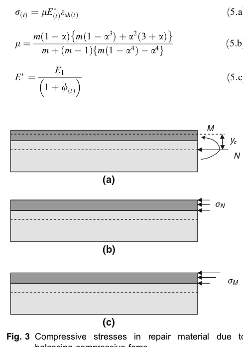
Further assessment of Fig.2c, it is noted that when tensile stress occurred in repair material the system is on condition of unbalance forces. For equilibrium of forces, a compres-sive force of N=r(t). Ar is required to be applied on the
system at the center of gravity of repair material where Ar
representing cross-section area of repair material. This compressive forceNcauses the composite system undergoes two type of compressive stresses i.e. axial stress rN due to
compressive force N applied on the center of gravity of composite and bending stressrMdue to momentM=Nyc
where yc is distance between center of gravity of repair
material and composite (see Fig.3). These two type of stresses have releasing effect on the shrinkage stress of repair material (Denarie et al.2011). Thus, the final stress occurred in repair materialrnew(t)becomes:
rnewðtÞ¼rð Þt rNrM ð4Þ
It is obvious thatrNis distributed evenly across the section
of repair material while rM distributed linearly with the
minimum at the interface between repair material and substrate concrete. For evaluation of shrinkage stress, the use ofrM at the interface will give a conservative value of
shrinkage stress. The values of bothrNandrMdepend upon
elastic modulus and dimension of both repair material and substrate concrete.
In the development of model to predict shrinkage stress as given above, the only time-dependent deformation property of substrate concrete which has been taken into account is shrinkage while creep is omitted. If shrinkage of substrate concrete is negligible, the differential shrinkage that causes shrinkage stress is equivalent to shrinkage of repair material itself. The elimination of substrate shrinkage could be accepted when substrate concrete being repaired is that of old concrete.
A different model has been proposed by Silfwerbrand (1996) where shrinkage stress r(t)may be calculated using
the following equations:
rð Þt ¼lEð ÞteshðtÞ ð5:aÞ
l¼mð1aÞ m1a
3
ð Þ þa2ð3þaÞ
mþ ðm1Þfmð1a4Þ a4g ð5:bÞ
E¼ E1 1þ/ðtÞ
ð5:cÞ
wooden base specimen steel ring restraint
end restraint specimen
specimen
substrate restraint
Fig. 1 Type of restraints.
(c) (a)
(b)
sh(t) sh-s(t)
(t) sh-r(t)
Fig. 2 The magnitude of shrinkage induces stress in repair
system.
(c) (b) (a)
N
M
N M
yc
Fig. 3 Compressive stresses in repair material due to
whereesh,E(*t)and lare shrinkage of repair material,
mod-ified elastic modulus of repair material and degree of restraint, respectively. Equation (5.a) indicates that stress induced by shrinkage is partially released by creep and a form of restraint. This restraint is due to stress distribution on composite system where Bernoulli’s hypothesis i.e. plane sections remain plane after bending is applied. The value of degree of restraint is always less than one and it is affected bymandawhich are, respectively, ratio of elastic modulus of substrate concrete E2 to E*and ratio of depth of repair
material d to total thickness of overlay plus substrate con-crete h. Creep coefficient /(t) is used to obtain E* from
elastic modulus of repair materialE1. Thus, creep is taken
into account to modify the value of elastic modulus of repair material and so its value is reduced. Several assumptions have been used for developing this shrinkage stress predic-tion model and those which represent parameters related to mechanism of shrinkage induces stress in repair material are outlined as follows: the shrinkage of repair material is esh
throughout the depth of material while shrinkage of concrete substrate is neglected; complete bond exists in the interface of repair material and substrate which provides full restraint of shrinkage; creep of the substrate concrete is negligible.
Carlsward (2008) proposed similar model with that of Silwerbrand. The only difference is that the method of Silfwerbrand is a one-step calculation i.e. a single stress value is calculated based on the final shrinkage whereas the method of Carlsward is an incremental procedure. The stress at any timetdue to shrinkage applied at timeti, is estimated
using the following equations:
rðt;tiÞ¼lE
t;ti
ð ÞeshðtiÞ ð6:aÞ
l¼mðt;tiÞð1aÞ mðt;tiÞ 1a 3
ð Þ þa2ð3þaÞ
mðt;tiÞþ ðmðt;tiÞ1Þ mðt;tiÞð1a 4Þ a4
ð6:bÞ
Et ;ti
ð Þ¼
E1ðt;tiÞ 1þ/ðt;tiÞ
ð6:cÞ
The total stress at any timetis calculated by summing the contribution from each increment as:
X1 i¼1
rðt;tiÞ ð7Þ
Other model to estimate shrinkage stress is proposed by Baluch et al. (2002) where shrinkage stress at timet,r(t), is computed by multiplying elastic modulus of repair material E(t)with total strain, in which total strain in repair material is
obtained from shrinkage esh(t) minus creep ecrp(t). The
contribution of elastic strain of repair material is omitted. The model is also developed by assuming that time-dependent deformation properties of substrate concrete are negligible. In addition, rigidity of substrate concrete is incomparable than that of repair material. In turn, effect of elastic deformation of substrate concrete could be ignored. This can be achieved when the size (thickness) of substrate concrete is far greater than that of repair material. Obviously, these assumptions
lead to similarity of the model with end restraint situation. The model is expressed in the following equations:
rðtÞ¼Et eshðtÞecrpðtÞ ð8:aÞ
The value of creep may be expressed in term of specific creepc(t)defined as creep due to unit of stress. Hence, Eq.
(8.a) turns to be:
rð Þt ¼
Etesh tð Þ
1þEcð Þt
ð8:bÞ
Many more models could be found in literatures (Weiss et al.1998; Yang et al.2000; Zhou et al.2008; Raoufi et al. 2011). Computation of shrinkage stress using these models require numerical techniques which are beyond the scope of this paper.
3. Comparison of Shrinkage Stress
Computed from Different Models
3.1 Input Parameters
Computation of shrinkage stress in patch repair system using a variety of prediction models requires input param-eters which are determined experimentally. The input parameters at least consist of shrinkage, creep and elastic property of repair material. When effect of deformation properties of substrate concrete are taken into account, the models require another input parameters to be determined i.e. shrinkage, creep and elastic property of substrate con-crete. The effect of releasing stress due to composite action could be included and for this reason dimension (thickness) of both repair material and substrate concrete are necessary. Various experimental results found in literatures are gathered to be used as input parameters for this current study. Type of material, dimensions of specimens, testing methods, age of testing and other relevance condition for measuring input parameters obtained from various sources are presented in Table1. With data extracted from these sources, the main parameters influencing the shrinkage stress are investigated.
3.2 Degree of Restraint and Stress Release
Various models as presented in previous section would be expected to give dissimilarity in the results of shrinkage stress prediction. The difference in estimating shrinkage stress calculated using various models could be identified from the degree of restraint and stress release considered by each model. If the magnitude of shrinkage of repair material at timetisesh(t), the shrinkage stress at timetis equivalent to
resh(t)=Eesh(t) when full degree of restraint is assumed.
However, these shrinkage stress will be reduced due to effect of creep and so, the value of elastic modulusEis modified by E(t) to account for creep at time t. The reduction in
effect of creep,l/, of repair material could be quantified as
The degree of stress release due to effect of creepw/will
be:
a. w/¼1l/¼1 1
ð2þ/tÞfor Eq. (1.c) b. w/¼1l/¼1 1
1þ/
ð Þ for model of Silfwerbrand
(Eqs. (5.a–5.c))
c. w/¼1l/¼1 1 1þ/t
;ti
ð Þ
for model of Carlsward
(Eqs. (6.a–6.c)) d. w/¼1l/¼1 1
1þ/t
ð Þ for model of Baluch et al.
(Eq. (8.b)).
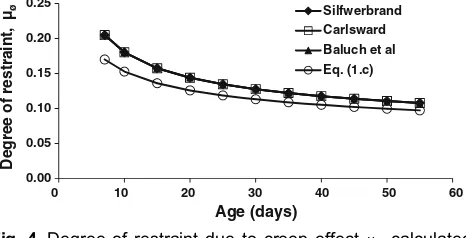
Comparison of degree of restraint due to effect of creep,lø,
of repair material accounted by various models is presented in
Figs.4and5. It is obvious that effect of creep to release stress is similar for model of Silfwerbrand (Eq. (5.a)), Carlsward (Eq. (6.a)) and Baluch et al. (Eq. (8.b)). On the other hand, in addition to creep effect, influence of elastic strain to release stress is also included in Eq. (1.c). Therefore, the degree of restraintl/used in Eq. (1.c) is lower than others. To reckon the
influence of elastic strain in releasing stress, superscript asterisk is used in the notation of degree of restraintl/. Based on data of creep coefficient (/(t)) and elastic modulus extracted
from Baluch et al. (2002) as input parameters, the value ofl/
of Eq. (1.c) is about 10–20 % below those of other models (Fig.4). For the whole data extracted from sources shown in Table1, the different between degree of restraint l/ of
Eq. (1.c) with those of other models could be quantified using polynomial expression as shown in Fig.5. It is seen that the values ofl/is in the range of 0.1–0.9 and it is reduced by about
40 % if effect of elastic strain is reckoned as in Eq. (1.c). In the meantime, the degree of restraint due to composite action,lc, used in Eqs. (5.a) and (6.a) could also be
iden-tified from Eqs. (5.b) and (6.b), respectively. In the devel-opment of model to predict shrinkage stress, the values ofl
Table 1 Sources of input parameters.
Information related to input parameters Source of data
Material Shrinkage Creep Elastic modulus
Repair material and substrate are concrete with compressive cube strength of 48 and 52 MPa
at 28 days, respectively; thickness
of repair material and substrate are 50 and 100 mm, respectively started 7 days after
casting 7 days after moistening
Estimated to E=34 GPa through evaluation of compressive stress on
cubes
Silfwerbrand (1996)
Repair material is high performance shrinkage substrate are 25 and 50 mm, respectively
Specimen: prism of
285925925 mm;
sealed in aluminium foil for 7 days prior to
curing
Specimen: prism of
300940940 mm
loaded in tensile creep rig
Evaluated according to ASTM C 307-94
Baluch et al. (2002), Carlsward (2006)
Repair material is mortar while substrate is concrete
having compressive strength of 25 MPa; thickness of repair material and substrate are
30 and 150 mm, respectively
Specimen: cylinder of 7.59275 mm; measurement started at
1 days after casting
Specimen: prism of
50091009100 mm
loaded in flexure; measurement started at
1 days after casting
Specimen:prism of
50091009100 mm;
tested in flexure in which stress and strain relationship in tension
was determined
Kristiawan et al. (2009)
Repair material is fibre reinforced concrete with
strength at 28 days is 51.5 MPa; thickness of
repair and substrate concrete are 50 and 300 mm, respectively
Specimen: prism of
5009100950 mm;
measurement started 5 days after curing
Specimen: cylinder of
1509300 mm loaded
in compression
Estimated based on compressive strength using CEB FIP MC90
in Eqs. (5.b) and (6.b) are derived from composite beam theory where Bernoulli’s hypothesis is applied. Thus, it can be deduced that the valuelrepresents the degree of restraint due to composite action lc. For Eq. (4) the value oflcis
wherewNandwMrepresenting degree of stress release due to
axial and bending action, respectively.
Figures6 and 7 show degree of restraint and stress releases due to composite action in the repair system for cases of beam having total thickness (included thickness of repair material) of 300 mm. For this parametric study, value of relative thickness of repair material to total thickness of composite systemais limited to 0.333 which corresponds to a maximum repair material thickness of 100 mm. This depth of repair material is thought to be a representation of max-imum depth of general patch repair on beam having depth of 300 mm. Generally, it is found that degree of stress release due to composite action used in Eq. (4) lc has exactly
similar value with l used in Eq. (5.a). The similarity of degree of stress release of both equations is not surprising since both of them derived from similar principle of com-posite action. It is also seen that for cases as in Figs.6and7, the value oflcis in the range of 0.44–0.87.
Effect of a is investigated at relative ratios of effective modulus of substrate concrete to repair materialm=1 (See Fig.6). It is confirmed that degree of restraint due to composite action decreases at diminishing rate when a is
increased linearly. Examining Fig.6, it is also discovered that the component of axial stress releasewN increases linearly
with a. On the contrary, the component of bending stress release wM increases in the beginning (lower a) and then
reaching a peak value before decreasing. It is also seen thatwN
is inferior than wM especially at lower a, but the trend is
reversed at a highera.
Effect ofmon degree of restraint could be examined from Fig.7. An opposite trend is shown if it is compared with the effect ofa. The degree of restraint due to composite action accounted in Eqs. (4) and (5.a) increase at diminishing rate. This behaviour is related to reduction of bothwNandwMas
mincreased. Thus, if relative property of elastic modulus of substrate concrete to repair material is increased continu-ously, the amount of stress released by axial and bending action in the composite system is reduced and approaching zero value. Consequently, degree of restraint is increased and shrinkage stress approach to its original value when stress release due to composite action is omitted.
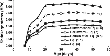
3.3 Magnitude of Shrinkage Stress Estimated by Various Models
An example result of shrinkage stress calculation are given in Fig.8using input parameters extracted from Baluch et al. (2002). As can be seen in this figure, different model will give different value of shrinkage stress with the higher shrinkage stress is obtained from the use of Eq. (8.b) or model of Baluch et al. followed by Eq. (1.c), and then Eq. (5.a) or model of Silfwerbrand and Eq. (6.a) or model of Carlsward. The lowest shrinkage stress is obtained with the use of Eq. (4).
0.00
Degree of restraint,
µø
Fig. 4 Degree of restraint due to creep effect l/calculated
using input parameters extracted from Baluch et al. (2002).
0.00 0.20 0.40 0.60 0.80 1.00
Degree of restraint,
µ
ø, Eq. (1.c)
µø, other models
Fig. 5 Relationship between degree of restraint due to creep
effectl/calculated from Eq. (1.c) and other models.
0.0
0.00 0.05 0.10 0.15 0.20 0.25 0.30 0.35
Degree of restraint
µ
Fig. 6 Degree of restraint l and stress release w due to
composite action on a beam with 300 mm thickness and m=1 at variousa.
Degree of restraint
µ
Fig. 7 Degree of restraint l and stress release w due to
The order of shrinkage stress values as seen in Fig.8 is predictable and could be related to the degree of stress releases considered by the models. Examining all the models as described in the previous section, it is clear that the stress release consists of two components i.e. due to effect of creep of repair material and due to effect of composite action. For model of Eq. (1.c), it considers not only stress release by creep but it also takes into account influence of elastic property of repair material. Meanwhile, the effect of com-posite action to release stress in repair material is neglected in Eqs. (1.c) and (8.b). None of the models takes into con-sideration other stress release which is caused by deforma-tion properties of substrate concrete. Model predicdeforma-tion which consider all possibilities of stress releases i.e. (Eq. (4)) will give the lowest magnitude of shrinkage stress and vice versa. Figure9 illustrates the magnitude of shrinkage stress com-puted by various models from its original value (resh(t)).
Original shrinkage stressresh(t)is a stress calculated where
none of degree of restraint is considered.
Comparison between shrinkage stress calculated using Eq. (8.b) and other models with input parameters taken from various sources (Table1) is given in Fig.10. Equation (8.b) could be viewed as the basic shrinkage stress prediction model where only stress release due to creep effect has been taken into account. If other stress releases would be inclu-ded, the magnitude of shrinkage stress should be reduced. Figure10clearly illustrates this situation. Generally, it can be said that elastic property of repair material could reduce shrinkage stress by 40 % (see relationship Eqs. (8.b) vs. (1.c) in Fig.10). Composite action could release shrinkage stress at 10 % more than effect of elastic property of repair material. Combination of elastic property and compos-ite action could bring shrinkage stress down to 29 % (see relationship Eqs. (8.b) vs. (4) in Fig.10).
4. Accuracy of the Models
Accuracy of the model to estimate shrinkage stress in patch repair system could be evaluated when concurrent data of input parameters and observed shrinkage stress are available. However, it is difficult to establish shrinkage stress measurement induced by substrate restraint which reflects actual deformation properties of substrate concrete. The available complete input parameters and shrinkage stress
data for evaluation of the models are those obtained from measurement of shrinkage stress induced by end restraint (Lange et al. 2003). If these data are used, only Eqs. (1.c) and (8.b) may be evaluated since these models neglecting the effect of substrate concrete properties.
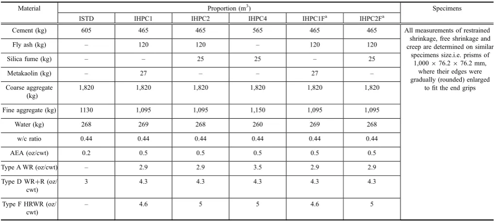
Table2 provides background information related to the materials and specimens used to measure input parameters and their corresponding shrinkage stresses. Free drying shrinkage strain, restrained drying shrinkage stress and creep were measured from the first day after casting. Details of experimental works could be referred to Lange et al. (2003). Based on these data of input parameters (free drying shrinkage strain and creep), shrinkage stress is estimated using model of Eqs. (1.c) and (8.b). The results of calcula-tion is compared with the shrinkage stress observed in restrained shrinkage stress measurement and presented in Fig.11. As can be seen from this figure, computation of shrinkage stress with Eq. (8.b) will give almost similar value with the measured shrinkage. The difference in estimating shrinkage stress is only less than 10 %. The 10 % overes-timate value of shrinkage stress by Eq. (8.b) could be tol-erated. Therefore, Eq. (8.b) may be accepted as a method to
0.00 0.50 1.00 1.50 2.00 2.50 3.00 3.50
0 10 20 30 40 50 60
Shrinkage stress (MPa)
Age (days)
Silfwerbrand Eq. (6.a) Carlsward - Eq. (7) Baluch et al Eq. (8.b) Eq. (1.c)
Eq. (4)
Fig. 8 Shrinkage stress estimated by different models (input
parameters extracted from Baluch et al.2002).
Shrinkage stress
Age
. sh(t)
µ.µø.
. sh(t)
µø. sh(t)
sh(t) Eq. (8.b) Eq. (1.c)
Eq. (5.a or 6.a) Eq. (4)
sh(t)
Fig. 9 Magnitude of shrinkage stress as influenced by
degree of restraint.
y = 0.5196x R² = 0.8521 y = 0.612x R² = 0.9087
y = 0.2954x R² = 0.5995
0.00 1.00 2.00 3.00 4.00 5.00 6.00
0.0 0 2.00 4.00 6.00 8.00 10.00
Shrinkage stress, Eq. (1.c); Eq. (4); Eq. (5.a)
Shrinkage stress, Eq. (8.b) Eq. (8.b) vs Eq. (5.a)
Eq. (8.b) vs. Eq. (1.c)
Eq. (8.b) vs Eq. (4)
Fig. 10 Relation between shrinkage estimated by Eq. (8.b)
predict shrinkage stress when effect of substrate concrete properties is ignored. On the other hand, application of Eq. (1.c) will underestimate shrinkage stress by 30 %. Hence, Eq. (8.b) is favorable compared to Eq. (1.c).
5. Simplified Model
Method to estimate shrinkage stress required several input parameters which have to be experimentally determined simultaneously. Based on the values of input parameters, shrinkage stress could be computed and the risk of cracking on repair material could be assessed. Thus, input parameters may be used to set criteria for assessing shrinkage cracking ten-dency of repair material. If a model is developed with huge variety of parameters to be taken into account, it certainly will create complexity in setting criteria for assessing shrinkage cracking. For this reason, it is desirable to reduce the input parameters to as minimum as possible without losing in accuracy of the model for estimating shrinkage stress.
Beushausen and Alexander (2007) proposed simplified model to estimate shrinkage stress which requires less input parameter than models presented in previous section. Strain produced in patch repair is a combination of shrinkage, relaxation and elastic strain. For most specimens they tested, measured repair material strains on composite members were approximately 35 % (between 30 and 40 %) of free repair material shrinkage strains esh and relaxation could be
esti-mated to reduce tensile repair material stress by approxi-mately 50 %. Therefore, they suggest strain which induces stressestress-producingin patching system as:
estressproducing¼ð10:35Þ0:5esh ¼0:33esh ð10Þ
This corresponds to shrinkage stress in repair material of:
r¼0:33E0esh ð11Þ
where E0 is elastic modulus of repair material. Thus, the
simplified model requires only two input parameters i.e. elastic and shrinkage property of repair material.
A constant factor of 0.33 in Eq. (11) represents combi-nation of degree of restraint due to creep and composite action. For degree of restraint provided by creepl/the value
is equivalent to 0.5 and for that due to composite actionlcit
is equal to 0.65 (see Eq. (10)). Hence, if a comparison is made between Eq. (11) and other models, the following conclusions are drawn. It seems that the value ofl/ =0.5
as suggested by Eq. (11) corresponds to average values ofl/
given by other models (see Fig.5). Meanwhile, the value of lc=0.65 matches with the mean values oflcas given in
y = 1.0604x R² = 0.7796
y = 0.6756x R² = 0.7593
0.00 0.50 1.00 1.50 2.00 2.50
0.00 0.50 1.00 1.50 2.00 2.50
Predicted Stress (MPa)
Measured Stress (MPa) Eq. (8.b)
Eq. (1.c)
Fig. 11 Comparison between predicted and measured
shrinkage stress (input parameters and measured shrinkage stress are extracted from Lange et al. (2003)).
Table 2 Information related to data used to validate model (after Lange et al. (2003)).
Material Proportion (m3
) Specimens
ISTD IHPC1 IHPC2 IHPC4 IHPC1Fa
IHPC2Fa
Cement (kg) 605 465 465 565 465 465 All measurements of restrained
shrinkage, free shrinkage and creep are determined on similar
specimens size.i.e. prisms of 1,000976.2976.2 mm,
where their edges were gradually (rounded) enlarged
to fit the end grips
Fly ash (kg) – 120 120 – 120 120
Silica fume (kg) – – 25 25 – 25
Metakaolin (kg) – 27 – – 27 –
Coarse aggregate (kg)
1,820 1,820 1,820 1,820 1,820 1,820
Fine aggregate (kg) 1130 1,095 1,095 1,150 1,095 1,095
Water (kg) 268 269 268 260 269 268
w/c ratio 0.44 0.44 0.44 0.44 0.44 0.44
AEA (oz/cwt) 0.2 0.5 0.5 0.5 0.5 0.5
Type A WR (oz/cwt) – 2.9 2.9 3.5 2.9 2.9
Type D WR?R (oz/ cwt)
3 4.3 4.3 4.3 4.3 4.3
Type F HRWR (oz/ cwt)
– 4.6 5 5 4.6 5
a
Figs.6 and 7 where the range of lc is from 0.44 to 0.87.
Thus, simplified model as given by Eq. (11) may be used to substitute model for estimating shrinkage stress in patch repair system where stress releases both due to creep and composite action are taken into account and the only avail-able input parameters are shrinkage and elastic modulus of repair material.
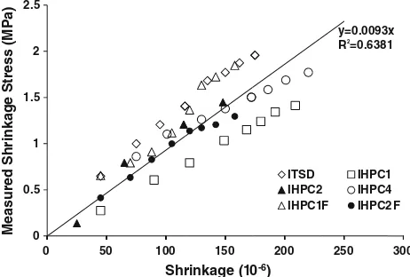
Other simplified model has been proposed by Kristiawan (2011) where shrinkage stress at any time t, r(t), may be
calculated using the following equation:
rð Þt ¼0:0093eshðtÞ ð12Þ
whereesh(t)denotes shrinkage at timet; and the unit of stress
and shrinkage is MPa and microstrain, respectively. The model is derived from regression analysis which relates the induced tensile stress with shrinkage. The data used for this analysis are taken from several literatures (Silfwerbrand 1996; Baluch et al. 2002; Weiss et al.1998; Hossain et al. 2008). It should be noted that the shrinkage stresses employed in the regression analysis are those estimated from shrinkage stress prediction models. When actual shrinkage stresses as measured in the laboratory are used (Lange et al. 2003), similar result is obtained as seen in Fig.12. Thus, complexity of the model is simplified by Eq. (12) where only shrinkage property is required to estimate shrinkage stress. All other factors influencing shrinkage stress in repair material are contained in the constant factor of 0.0093. Since this simplified model is derived from data of measured shrinkage where restraint is provided by end restraint, the model (Eq. (12)) could only be used to substitute Eq. (8.b) where rigidity of substrate concrete is far greater than that of repair material as in the case of thin repair overlay system.
6. Conclusions
Various models to predict shrinkage stress in patch repair system has been suggested in literatures and the different values of shrinkage stress computed by these models could be traced from the difference degree of restraint and stress release considered by each model. Based on the provided data within the scope of the current study, the degree of
restraint due to effect of creepl/is in the range of 0.1–0.9.
Meanwhile, the degree of restraint due to composite action lcis in the range of 0.44–0.87.
Accuracy of the models to estimate shrinkage stress in patch repair system is evaluated based on available concur-rent data of input parameters and observed shrinkage stress. For this current study it is confirmed that shrinkage stress estimated from model considering effect of creep to release stress (Eq. (8.b)) is slightly (not more than 10 %) higher than measured shrinkage stress. On the other hand, if elastic strain is also included (Eq. (1.c)), it will underestimates shrinkage stress by about 30 %. For this reason, Eq. (1.c) and other equation derived from this i.e. Eq. (4) are not recommended to be used for estimating shrinkage stress.
Two simplified models (Eqs. (11) and (12)) have been suggested where each of which has distinctive application. Equation (11) may be used to substitute model for estimating shrinkage stress in patch repair system where stress releases both due to creep and composite action are taken into account and the only available input parameters are shrink-age and elastic modulus of repair material. Meanwhile, Eq. (12) may be used to substitute Eq. (8.b) where the only stress release taken into account is that due to creep as in the case of thin repair overlay system and the available input parameter is the magnitude of shrinkage alone.
Acknowledgments
This work is part of comprehensive research to develop performance related criteria of patch repair system which is funded by Directorate General of Higher Education through Hibah Kompetensi (contract no. 134/SP2H/PL/Dit.Litab-mas/III/2012).
Open Access
This article is distributed under the terms of the Creative Commons Attribution License which permits any use, distribution, and reproduction in any medium, provided the original author(s) and the source are credited.
References
AASHTO. (2006). Standard practice for estimating the crack tendency of concrete (pp. 34–99). Washington, DC: AASHTO Provisional Standards.
ASTM C1581. (2007). Standard test method for determining age at cracking and induced tensile stress characteristics of mortar and concrete under restrained shrinkage. West Conshohocken: ASTM.
ASTM C928-00. (2000).Standard specification for packaged dry rapid-hardening cementitious materials for concrete repairs. West Conshohocken: ASTM.
ASTM C1600-07. (2007). Standard test method for rapid hardening hydraulic cement. West Conshohocken: ASTM.
0 0.5 1 1.5 2 2.5
0
Measured Shrinkage Stress (MPa)
50 100 150
Shrinkage (1
200
0-6) ITSD IHPC2 IHPC1
250 IHPC1 IHPC4
F IHPC2
300 F y=0.0093x R =0.63812
Baluch, M. H., Rahman, M. K., & Al-gadhib, A. H. (2002). Risks of cracking and delamination in patch repair.Journal of Materials in Civil Engineering, 14(4), 294–302. Bentur, A., & Kovler, K. (2003). Evaluations of early age
cracking characteristics in cementitious system. Materials and Structures, 36, 183–190.
Beushausen, H., & Alexander, M. G. (2007). Performance of concrete patch repair systems. In C. U. Grosse (Ed.), Advances in construction materials(pp. 255–262). Berlin: Springer.
Carlsward, J. (2006). Shrinkage cracking of steel fiber rein-forced self compacting concrete overlays: Test methods and theoretical modelling. Doctoral thesis, Lulea University of Technology, Department of Civil and Environmental Engineering, Division of Structural Engineering, Lulea˚, Sweden.
Carlsward, J. (2008). Test methods and theoretical model to assess shrinkage cracking of steel fibre reinforced concrete overlays.Nordic Concrete Research, 38, 51–68.
Denarie, E., Silfwerbrand, J., & Beushausen, H. (2011). Struc-tural behaviour. in B. Bissonnette, L. Courard, D. W. Fowler, & J. L. Granju (Eds.),Bonded-cement based material overlays for repair,the lining or the strengthening of slabs or pavements. State of the art reports of the RILEM technical committee 193-RLS (pp. 81–106). New York: Springer.
Hongkong Housing Authority. (1991).Practice notes for con-crete repair. Hong Kong: Hongkong Housing Authority. Hossain, A. B., Fonseka, A., & Bullock, H. (2008). Early age
stress development, relaxation and cracking in restrained low w/b ultrafine fly ash mortars. Journal of Advanced Concrete Technology, 6(2), 261–271.
Kristiawan, S. A. (2011). Compatibility of shrinkage between patch repair material and concrete (in Indonesian).Journal Teknik Sipil, 18(2), 103–118.
Kristiawan, S. A., Mahmudah, A. M. H., & Sunarmasto. (2009). Cracking resistance of concrete overlays as predicted from
the development of shrinkage stress. InProceeding of 3rd international conference on concrete repair(pp. 157–160). Padua: ICCR.
Lange, D. A., Roesler, J. R., D’Ambrosia, M. D., Grasley, Z. J., Lee, C. J., & Cowen, D. R. (2003). High performance concrete for transportation structures. Final report: pre-pared for Illinois Department of Transportation, Bureau of Materials and Physical Research. Urbana: Department of Civil and Environmental Engineering, The University of Illinois at Urbana–Champaign, Illinois, USA.
Matthews, S. (2007). CONREPNET: Performance based approach to the remediation of reinforced concrete struc-tures: Achieving durable concrete structures. Journal of Building Appraisal, 3(2), 6–20.
McDonald, J. C., Vaysburd, A. M., & Poston, R. W. (2000). Performance criteria for dimensionally compatible patch repair materials.HPM&S Bulletin, 00–1, 1–13.
Rahman, M. K., Baluch, M. H., & Al-Gadhib, A. H. (2000). Simulation of shrinkage distress and creep relief in concrete repair.Composites Part B Engineering, 31, 541–553. Raoufi, K., Pour-Ghaz, M., Poursaee, A., & Weiss, J. (2011).
Restrained shrinkage cracking in concrete elements: Role of substrate bond on crack development. Journal of Materials in Civil Engineering, 23(6), 895–902.
Silfwerbrand, J. (1996). Differential shrinkage in normal and high strength concrete overlays.Nordic Concrete Research, 19, 55–68.
Weiss, W. J., Yang, W., & Shah, S. P. (1998). Shrinkage cracking of restrained concrete slabs. Journal of Engi-neering Mechanics, 124(7), 765–774.
Yang, W., Weiss, W. J., & Shah, S. P. (2000). Predicting shrinkage stress field in concrete slab on elastic subgrade. Journal of Engineering Mechanics, 126(1), 35–42. Zhou, J., Ye, G., Schlangen, E., & van Breugel, K. (2008).