MATHEMATICAL MODELING AND
SIMULATION OF FLUID DYNAMIC IN THE
CONTINUOUS STIRRED TANK
Tulus, Opim Salim Sitompul, Sawaluddin and Mardiningsih
Abstract. This study examines the fluid dynamic models of stirring water con-tinuously in the tank. The model is derived by using a Navier-Stokes equation. It is considered the energy balance and linearization. Simulation is built by using the Navier-Stokes euation. In the results and discussion has been developed two simulation cases, i.e. in the speed of 10rpm and 20 rpm. From the results and discussion it can be concluded that the velocity magnitude distributions in the case of speed variation are different. In the speed of 10rpm the velocity distribution more irregular which compared with the speed of 20rpm.
1. INTRODUCTION
Crude palm oil is a foreign exchange earner for Indonesia mainstay of the plantation industry. It can be seen from the CPO market share with approx-imately 80% of palm oil on the market is the world produced by Indonesia and Malaysia. Various attempts have been made to improve the perfor-mance of the palm oil industry. One of them is through the garden-livestock integration system or known as system integration palm-cow (SISS). This system has been proven to increase productivity and farmers’ welfare in
Received 25-04-2015, Accepted 28-07-2015.
2010 Mathematics Subject Classification: 65L60, 76D05, 81T80
Key words and Phrases: Fluid Dynamic, Finite Element Method, Navier-Stokes Equation.
which profits not only from the plantation sector but also from the livestock sector. However, the problem of waste is still a major obstacle in the CPO industry sector. On the other hand, the wastewater treatment system of palm oil mill is one of the major sources of emissions of greenhouse effect gases (GHG) [1].
Waste generated from palm oil industries including heavy waste cate-gories with high quantity and content of contaminants that can reach up to 20000-60000 mg/l and 40000-120000 mg/l respectively for BOD (biochemi-cal oxygen demand) and COD (chemi(biochemi-cal oxygen demand ). Waste is mainly generated from the boiling stage, precipitation, decantation, and centrifu-gation were carried out during the clarification process CPO. Wastewater produced from this stage no less than 2.5 m3/ton CPO products. If the projected production of 10 million tons launched reached, it will produce approximately 25 million m3 of wastewater. Waste in the form of heavy condensate phase and thus the characteristics are very difficult to overcome only with the concept of end-off pipe treatment alone. Major issue then is where the technological constraints of existing wastewater treatment is cur-rently difficult to produce output that leads to a waste-free CPO industry [19].
The competitiveness of an industry is not only determined by the num-ber, quantity, and price of the products, but is also determined by the production process used primarily for the production of export-oriented. Moving on from the problems encountered in the field, integrated solutions from program zero waste effluent and farm-livestock integration in the palm oil industry is a very attractive alternative to resolve the issue of industrial waste.
According to the information from the Ministry of Agriculture of In-donesia, the issue of renewable energy has become a huge talking point in Indonesia at this time, began to decrease in reserves related to energy de-rived from petroleum. Other energy sources must be sought with the use of natural resources in Indonesia alone. One of the beneficiaries of the re-sources that can be used is the utilization of palm oil mill effluent (POME). With oil palm plantations which reached seven million hectares in 2011, with productivity 3595Kg/Ha [5]. Obviously this needs to be developed POME utilization.
another section, Irvan et al. [18] have also successfully done the conversion on a pilot scale using fermenter capacity of 3000 liters at a temperature of 55◦C, and a closed system. With a hydraulic retention time of 25, the gas
produced approximately 3 m3, which is equivalent to 25 liters for every 1
liter POME fed.
Garrido et al. [12, 14] have examined the related simulation phe-nomenological theory of sedimentation-consolidation processes for continu-ous batch settling and thickening of the suspension. Results obtained in the form of two alternatives. Input a solid rate and concentration flux flow downward. If the thickener widely known, the capacity and the concentra-tion profiles in the equipment can be predicted.
2. MATHEMATICAL MODELING
In the problem of continuous stirred tank reactor, Mathematical mod-eling of a continuous stirred tank reactor numerically can be derived from some of assumptions: a complete mixture in the reactor and its cover, and a constant reactor volume and its cover.
The mathematical model of the process as formulated by using the mass that out from the tank and an energy balance, and by considering constitutive equation.
2.2. Mass balance in the reactor
Mass balance equation of reactor is denoted as the following equation:
VdCP
dt =q(CP0−CP)−V rP (1) withCP is a the concentration of the component productP in the reactor, and rP is the speed of reaction per unit volume. Reaction product in first order is written in the following equation,
rP =k0exp
2.3. Reactor Balance Energy
Reactor energy balance is denoted by using the following equation:
V ρCp
where (−∆H) is reaction heat,hP is coefficient of heat transfer,T0is feeding temperature, and Tc0 is the coolant temperature in the inlet. From the
equation 1 - 3, the mass balance and energy balance equation of continuous stirred tank reactor is written as follows:
dCP
The model equation of continuous stirred tank reactor as written in the equation 4 and 5 consist a nonlinear function in T and CP. They inte-grated and it is not possible to solve one equation independently to another. To design a controller for such nonlinear process, it can be used a system of locally linear model.
2.4. The form of State Variables of Equation
3. RESULTS AND DISCUSSION
3.1. Simulation using COMSOL Multiphysic
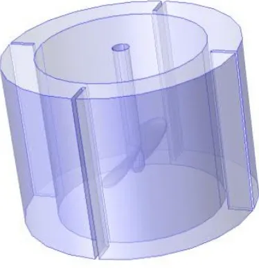
Simulation is preformed using COMSOL as follows. Two cylinder are generated coincide. The inner domain is representated by a rotating (apa-tial) frame and the outer domain by a fixed (material) frame. The baffled stirred mixer is built of an impeller that rotates counterclockwise at a speed of 10 rpm and 20 rpm. First of all, the fluid is water. Figure 1 shows the corresponding 3D model.
Figure 1: Geometry Model
The objective is to analyze the fluid dynamic in the tank, i.e the shear rate, the velocity magnitude, and the velocity field. The equation of Navier-Stokes is assumed to give the dynamic as in Equation 8.
ρ∂u
∂t +ρ(u· ∇)u = ∇ ·
ρi+µ ∇u+ (∇u)T
−2
3µ(∇ ·u)i
+F
∂ρ
∂t +∇ ·(ρu) = 0 (8)
Equation 12. In the model it is also assumed the symmetry for upper of domain as in the Equations 13 - 15.
u = 0 (9)
By using Finite Element Method, the mesh is generated using tetra-hedron as depicted in Figure 2. A careful selection of the mesh type and number is considered before the simulation. These have a significant influ-ence for calculation accuracy and efficiency. In 90% of the overall volume of the CSTR hexahedron mesh type is used in the meshing scheme for its higher calculation accuracy in 3-dimension multi-phase simulation.
3.2. Velocity Magnitudes
Case: Speed 10 rpm
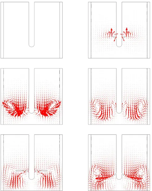
The velocity magnitudes for the speed of 10 rpm are vary in the slice of the blade level. It shows a clockwise directed circulation pattern governing most of the cross-section. Only flow areas before and behind baffles show flow distortions and a low average velocity. The central region below the area swept by the moving impeller shows an intense tangential circulation flow. Outside the central region the tangential velocity component is decreasing and passing into a stronger radial velocity component.
Case: Speed 20 rpm
Figure 2: Mesh of Model
3.3. Velocity Fields
4. CONCLUSION
Figure 3: Velocity Magnitude using speed 10 rpm
REFERENCES
1. Yacob, S., Hassan, M.A., Shirai, Y., Wakisaka, M., Subash, S. 2005. Baseline study of methane emission from open digesting tanks of palm oil mill effluent treatment. Chemosphere, Vol. 59, pp. 1575–1581.
2. F. Concha, M.C. Bustos. 1985. Theory of sedimentation of flocculated fine particles. In B.M. Moudgil, P. Somasundaran (Eds.). Proceedings of the EF Conference on Flocculation, Sedimentation and Consolidation, Sea Island, GA, AIChE, New York, p. 275–284.
3. Sri Wahyuni. 2011. Biogas. Jakarta: Penebar Swadaya
Se-Figure 4: Velocity Magnitude using speed 20 rpm
baran Pencemaran Udara (NO2). Jurnal Materi dan Pendidikan Fisika. pp. 40–43
5. Dinas Pertanian. 2011. Statistik Perkebunan Indonesia. Kelapa Sawit (Oil Palm). [www.deptan.go.id/infoeksekutif/bun/eis-bun2011/ Produk-tivitas%20sawit.pdf] accessed tgl. 15 Maret 2013.
6. Beioglu, A., Panaitescu, V. and Robescu, D. 2010. Mathematical Mod-eling and Numerical Simulation of Sludge Thickening Processes in Grav-itational Sludge Thickeners. U.P.B. Sci. Bull., Series D, Vol. 72, Iss. 2, pp. 213–218.
Figure 5: Velocity Field speed 10 rpm
8. B¨urger, R. & Concha, F. 1998. Mathematical model and numerical sim-ulation of the settling of flocculated suspensionsInternational Journal of Multiphase Flow. 24, pp. 1005–1023
9. B¨urger, R., Bustos, M.C., & Concha, F. 1999. Settling velocities of par-ticulate systems: 9. Phenomenological theory of sedimentation processes: numerical simulation of the transient behaviour of flocculated suspen-sions in an ideal batch or continuous thickener Int. J. Miner. Process. 55. 267–282
10. Warsi, Z.U.A. 1981. Conservation form of the Navier-Stokes equations in general non-steady coordinates. AIAA Journal 19 (2): 240–241.
suspen-sions. Chemical Engineering Journal80, pp. 91–104.
12. Garrido, P., Burgos, R., Concha, F. and Brger, R. 2003. Software for the design and simulation of gravity thickeners. Minerals Engineering16, pp. 85–92.
13. Yan Fauzi, Yustina E. Widyastuti, Imam Satyawibawa & Rudi H. Paeru. 2012. Kelapa Sawit.Jakarta: Penebar Swadaya.
14. Garrido, P., Burgos, R., Concha, F. and Brger, R. 2004. Settling veloc-ities of particulate systems: 13. A simulator for batch and continuous sedimentation of flocculated suspensions. Int. J. Miner. Process. 73, pp. 131–144.
15. D. M. Causon & C. G. Mingham. 2010. Introductory Finite Difference Methods for PDEs. Manchester: Ventus Publishing ApS.
16. Randall J. LeVeque. 2005. Finite Difference Methods for Differential Equations.
17. Patankar, S. V. 1980. Numerical heat transfer and fluid flow. New York: Hemisphere Publishing Corporation.
18. Irvan, Trisakti, B., Wongistani, V., Tomiuchi, Y. 2012. Methane Emis-sion from Digestion of Palm Oil Mill Effluent (POME) in a Thermophilic Anaerobic Reactor. Internat. J. of Sci. and Eng., Vol. 3(1), pp. 32–35
19. Irvan. 2012. Effect of Ni and Co as Trace Metals on Digestion Perfor-mance and Biogas Produced from The Fermentation of Palm Oil Mill Effluent. Internat. J. Waste Resources, Vol. 2(2)2012:16–19
20. Tulus. 2008. Pemodelan penyaringan air limbah pabrik kelapa sawit.
Prosiding Konferensi Nasional Matematika XIV, Palembang, 24-27 Juli 2008. pp. 607-616.
21. Jim C. Chen, Menachem Elimelech, Albert S. Kim. 2005. Monte Carlo simulation of colloidal membrane filtration: Model development with ap-plication to characterization of colloid phase transition. Journal of Mem-brane Science. Volume 255, Issues 12, 15 June 2005, Pages 291–305
Tulus: Department of Mathematics, University of Sumatera Utara, Medan
E-mail: [email protected]
Opim Salim Sitompul: Department of Information Technology, University of Sumatera Utara, Medan
E-mail: [email protected]
Sawaluddin: Department of Mathematics, University of Sumatera Utara, Medan
Mardiningsih: Department of Mathematics, University of Sumatera Utara, Medan