UNEXAR
–
Mini AUV Design & Measurement
UNEXAR
–
Desain dan Pengukuran Mini-AUV
N. Faidhon
J. Agung N.
S. Unang
Abstract— UNEXAR is a mini autonomous underwater robot in a cubic shape similar to a drone. This robot can be used to monitor local environment and observe an object below much more closely than otherwise needing us to wear underwater suit which is bothersome. It can also be used as an exploration device, to map unreachable area somewhere that’s not in our line of sight. Robot can also be used to find an object with specific color using camera and image processing in debian based operating system. Other than that as an AUV it is able to carry some load and transport it somewhere near as long as the power is sufficient. AUV Design compromised by planting artificial intelligence, planning the mechanical structure and electronics design. Component primarily discussed are locomotion mechanism, particle density and buoyancy. Experiment data, measurement data, failures and lesson learned from the research are also included.
Index Terms— Buoyancy, Engineering, Locomotion, Mechanical, Monitor, Particle density, Robot.
I. INTRODUCTION
A. UNEXAR
UNEXAR is a creative student project, it stands for Underwater Exploration Autonomous Robot, an AUV actually. Target requirement of this project itself is to design an underwater robot that will fit in a dimension of 30𝑥30𝑥30 cm3. It was easy, but we think the project target need to be reworked. A new requirement are now include added functionality, task completion test (performance), cost, environment, size and weight.
The main function of the robot for us actually, is a drone. However with improved hardware and sensors this robot can be much more useful. This robot can be used to monitor local environment and observe an object underwater much more closely than otherwise needing us to wear a diving suit which is bothersome. It can also be used as an exploration device to map unreachable area or out of sight area. Like deep ocean or area covered by some wall or even ice. However, robot’s diving capability are very limited. Because of the non-metallic material, render the robot susceptible to external pressure. Also observation performance by using camera varies depend on clarity of the water.
This project has been funded by Indonesian Departement of Educational. Estimated to be completed by the end of June 2015. The result of this project will be told in conclusion.
B. Related Work
It began in 1957, in applied physic laboratory, University of Washington, Professor Terry Ewart and his friend built the first Autonomous Underwear Vehicle (AUV). They called it the “Special Purpose Underwater Research Vehicle (SPURV)”, and used it to study diffusion, acoustic transmission and submarine wakes. Since then, many others followed [1]. But even so, AUV research are still very few compared to other robotic research because of expensive cost and environmental settings (water are not exactly favourable environment for electronic devices).
According to [2] “During the last decades, AUVs have gone through notable developments. In the late eighties and early nineties, the first prototypes required a tremendous effort and ingenious engineering solutions to compensate for the technological limitations in terms of computational power, batteries, and navigation sensors. To deploy these expensive vehicles navigating autonomously in a very unforgiving environment, and expecting them to return safely was a true act of faith in engineering, a scaled version of the early efforts in space technology.”
The applications of underwater vehicles have shown a dramatic increase in recent years, such as, mines clearing operation, feature tracking, cable or pipeline tracking and deep ocean exploration. According to different applications, the mechanical and electrical configuration and shape of an underwater vehicle are different. For instance, manipulators are necessary when doing mines clearing operation or some other tasks which need to deal with environment. If an underwater vehicle is used for underwater environment detection or observation, it is better to make this vehicle smaller and flexible in motion that it can go to smaller space easily.[3]
Paddle wheel thrusters are the most common and traditional propulsion methods for underwater vehicles. Usually, there are at least two thrusters installed on one underwater vehicle, one for horizontal motion and the other for vertical motion. The disadvantages of paddle wheel thrusters are obvious, for example, it is easy to disturb the water around the underwater vehicles. Meanwhile, the more the paddle wheel thrusters are used, the weight, noise and energy consumption increases.
The steering strategies of traditional underwater vehicles are changing the angular of rudders or using differential propulsive forces of two or more than two thrusters. Of course, there are vectored propellers being used on underwater vehicles. Reference [8] and [9] present underwater vehicles with vectored thrusters. Reference [10] proposes multi-channel hall-effect thrusters which involves vector propel and vector composition. Reference [11] proposes an autonomous underwater vehicle equipped with a vectored thruster. At the same time, the design of vectoring thrusters used on aircrafts is also an example of vectored propulsion system [12], [13] and [14].
II. HARDWARE DESIGN
Hardware consideration is probably the most important part of this project. It affect overall performance of the device. If it’s done the wrong way, we might find disastrous problem. This
AUV has cubical-shape, its dimension is 30𝑥30��30 cm3. Which is smaller than those in [3]. We spend most of our working time here, wondering, hesitating, imagining and thinking about how can we made such thing and finally we came up with this.
(1-2) Watertight Box (3) Hull Interconnection (4) Hull Chassis (5-8) Propeller (9) Reservoir
Figure 1. Mechanical Design.
The mechanical structure of this AUV consist of 5 parts, see Fig.1. The Ingress Protection rating of 67 (IP67) watertight box used to hold electronic component such as Central processing unit (CPU), Accelerometer, Gyroscope, Electronic Speed Controller (ESC) and other Electronic Board. Chassis is the main body frame of this AUV every other parts are placed firmly here. Reservoir are variable chamber used to adjust buoyancy. We can fill it with air to get a positive buoyancy [19].
Figure 2. Preliminary Design.
Fig.2 show preliminary system design that’s already implemented in the robot. Another new target requirement as mentioned in the first section is cost. Indonesian Departement of Education provide us a thousand dollars to complete this project. Total cost of making this AUV must not exceed that fund. Therefore we have to think and choose our component carefully. After collecting many references we decided to build our AUV using these component. The main processing unit in this project is BeagleBone Black Rev C. For sensing tool, we use ITG3200, ADXL345, HM4100 and C615, all of them are available in the market. For actuating mechanism we use Towerpro 2408-21t brushless motor and Hobbyking 20A ESC.
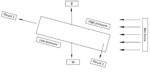
Figure 3. Dynamics Model.
The force acting on the vehicle when it moves can be seen in Fig. 3, there are 5 forces in total. Buoyant Force (β) is an upward-force caused by water displacement by vehicle’s body. For more information about vehicle's buoyancy you can refer to section IV straightaway. Weight (W) is a pulling force from the earth caused by vehicle’s mass multiplied by a constant of gravity (g). Net Force is a normal-force caused by fluids when it collides against an object, it will increase proportionally as the speed increase. Note that Fig. 3 show the Net Force when AUV move horizontally to the right because this force will always work in the opposite direction as the vehicle’s movement. Thus Force is also creating an area of high and low pressure as seen in Fig.3, that will [15]. The other force is internal system force of a brushless motor controlled by CPU via ESC
III. MOTION MECHANISM
First and foremost, the main actuator for this AUV is four brushless motor located in each side of a square-shaped base. The front motor are vertically mounted, while the rear placed horizontally. This is the part that steers, accelerates and stops the robot. Here’s how the AUV will maneuver, and to where each motor will thrust.
Motor Direction
Front Back
Left Right Left Right
Forward Push Push Push Push
Backward Pull Pull Pull Pull
Forward-Down - - Push Push
Backward-Up - - Pull Pull
Turn Left - - - Push
Turn Right - - Push -
Up Push Push - -
Down Pull Pull - -
Up-Left Push Push - Push
Up-Right Push Push Push -
Down-Left Pull Pull - Push
Down-Right Pull Pull Push -
Table I. Propeller to Direction. IV. NEUTRAL BUOYANCY
According to Archimedes’ principle, buoyant force has a magnitude equal to the weight of the fluid displaced [15]. In order to achieve neutral buoyancy state, a robot must be as dense as the water [16]. Meaning, the ratio of robot’s volume per mass must be equal to 1g/cm3 [17]. Data measurement of each component are shown below.
Table II. Volume Measurement
Name N Volume(in cm3)
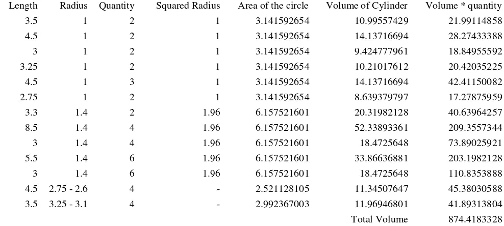
PVC Tube (see Tab. III) 1 874.4183328
IP67 Watertight Box 2 847.8
Aluminium Junction 1 13.5
Acrylic Base 1 712.8445528
Actuator Brushless Motor 4 18.5
As shown in Fig. 3 & 4, we’ve tilted the robot initial position intentionally about -15o to distribute the load for each actuators and lessen unnecessary movement. This is a pre-designed idea considering power efficiency because of 1300 mAH battery limitation but it can be reworked in the process. Power consumption of the system (brushless motor included) tested outside of water is 1480 mAH, meaning it will last less than an hour. When tested under-water however, the 4A Fuse break. We haven’t test how much power consumed by this submerged UAV with all the system running, but we know it work normally only for quarter of an hour .
Tab. 1 show the thrust of each motor for each navigation command, that means the robot will actually move in the opposite direction. Note when Front motor Push, it means vehicle will move upward. Whereas when Back motor Push, it means vehicle will move forward.
Volume measurement of the main chassis and watertight box are done by design software. The Reservoir and Brushless Motor however are measured manually by either calculation (Tab. III) or by measuring the water displaced. This robot is designed carefully, have gone through many kind of test, and designed to float in the middle of the water without needing external force of a brushless motor to stabilize. Total volume shown in Tab. 2 is 3370.362886 cm3. So we need the robot to be approximately 3370gr, hence neutral buoyancy state is fulfilled. This provide information to decrease trial and error probabilities.
The actual experiment however, show 3370 gr of load are too heavy, but with several tries we manages to get it float at 3277 gr as in Fig. 2. There’s a 100 gr difference between calculation and actual experiment, this is possibly because of error in the measurement or because the water density isn’t exactly 1 g/cm3. Pure water at 4o C does have a density value of 999,97kg/m, but as the temperature increase, density value will decrease [18].
Table III. Tube Volume Measurement
Length Radius Quantity Squared Radius Area of the circle Volume of Cylinder Volume * quantity
3.5 1 2 1 3.141592654 10.99557429 21.99114858
4.5 1 2 1 3.141592654 14.13716694 28.27433388
3 1 2 1 3.141592654 9.424777961 18.84955592
3.25 1 2 1 3.141592654 10.21017612 20.42035225
4.5 1 3 1 3.141592654 14.13716694 42.41150082
2.75 1 2 1 3.141592654 8.639379797 17.27875959
3.3 1.4 2 1.96 6.157521601 20.31982128 40.63964257
8.5 1.4 4 1.96 6.157521601 52.33893361 209.3557344
3 1.4 4 1.96 6.157521601 18.4725648 73.89025921
5.5 1.4 6 1.96 6.157521601 33.86636881 203.1982128
3 1.4 6 1.96 6.157521601 18.4725648 110.8353888
4.5 2.75 - 2.6 4 - 2.521128105 11.34507647 45.38030588
3.5 3.25 - 3.1 4 - 2.992367003 11.96946801 41.89313804
V. CONTROL SYSTEM
Control system used in this vehicle is PID controller with it’s constants generated via Genetic Algorithm. The generation of this constants have been automatically specified continuously. It was done by my friend and the research paper is also proposed in the conference entitled “Implementation of real value genetic algorithm to determine three PID parameter”.
This work has proven again that Archimedes was right and we acknowledge him as a great science figure. The measurement data laid out here might not be perfectly precise, but we have tried to get it as close as possible, even though the result were a little different from the experiment. With improved control this AUV can be turned into an underwater drone as it’s equipped by Full-HD camera, pressure sensor, and RF module
As an AUV this robot can carry a theoretical load of 3 kilogram. But somehow cannot last for more than half of an hour when operated underwater because of power limitation of battery.
ACKNOWLEDGMENT
This work supported by Telkom University and funded by the Ministry of Research, Technology and Higher Education (in Creative Student Project), Indonesia. We would like to thank the committee of Blue Techno Fest, for their help. We also thank Electronics and Intelligence Robotic Research Group Laboratory for providing us the tools needed to develop our vehicle.
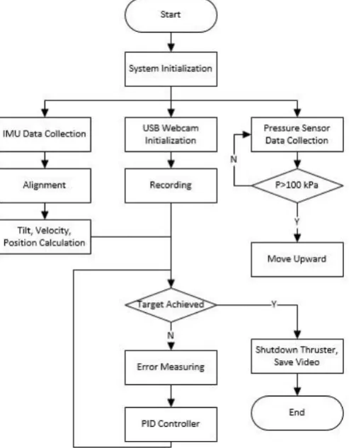
Figure 5. flowchart of the system planted in UNEXAR.
Summary of how the robot will do it’s work are shown in Fig. 5. It can be understood easily even without explanation, hence this research paper has fully describing the design of our vehicle named UNEXAR.
VI. CONCLUSION
To our knowledge this AUV has a new kind of design, with cubic-shaped body and four motor. It was tilted to distribute the load of movement to each motors (this will increase life-time we suppose) and to lessen unnecessary thrust. But we know now that tilting this AUV will most likely cause it to generate downward force of submarine wakes, but it will be handled by the control. Locomotion proposed here, very much alike to those of quadqopter but with a different placement direction. This will allow us to turn and maneuver very fast compared to torpedo- shaped AUV.
REFERENCES
[1] R. Kevin. “Mobile Robot: High-impact Emerging Technology - What You Need to Know: Definitions, Adoptions, Impact, Benefits, Maturity, Vendors”, Emereo Publishing, 2012, 12. [2] Nuno A. Cruz. “Autonomous Underwater Vehicle”, InTech,
2011, 9.
[3] Guo Shuxiang, Lin Xichuan. “Development of Vectored Water- Jet-Based Spherical Underwater Vehicle”, InTech, 2011. [4] Sangekar, M., Chitre, M. & Koay, T. (2009). Hardware architecture
for a modular autonomous underwater vehicle STARFISH,OCEANS 2008, IEEE, pp. 1–8.
[5] Allen, B., Stokey, R., Austin, T., Forrester, N., Goldsborough, R., Purcell, M. & von Alt, C. (2002). REMUS: a small, low cost AUV; system description, field trials and performance results,OCEANS’97. MTS/IEEE Conference Proceedings, Vol. 2, IEEE, pp. 994–1000.
[6] Madhan, R., Desa, E., Prabhudesai, S., Sebastião, L., Pascoal, A., Desa, E., Mascarenhas, A., Maurya, P., Navelkar, G., Afzulpurkar, S. et al. (2006). Mechanical design and development aspects of a small AUV–Maya,7th IFAC Conference MCMC2006.
[7] Antonelli, G., Chiaverini, S., Sarkar, N. & West, M. (2002). Adaptive control of an autonomous underwater vehicle: experimental results on ODIN,IEEE Transactions on Control Systems Technology9(5): 756–765.
[8] Cavallo, E., Michelini, R. & Filaretov, V. (2004). Conceptual design of an AUV Equipped with a three degrees of freedom vectored thruster,Journal of Intelligent & Robotic Systems 39(4): 365–391.
[9] Le Page, Y. & Holappa, K. (2002a). Hydrodynamics of an autonomous underwater vehicle equipped with a vectored thruster,OCEANS 2000 MTS/IEEE Conference and Exhibition, Vol. 3, IEEE, pp.2135–2140.
[11] Le Page, Y. & Holappa, K. (2002b). Simulation and control of an autonomous underwater vehicle equipped with a vectored thruster,OCEANS 2000 MTS/IEEE Conference and Exhibition, Vol. 3, IEEE, pp.2129–2134.
[12] Kowal, H. (2002). Advances in thrust vectoring and the application of flow-control technology, Canadian aeronautics and space journal48(2): 145–151.
[13] Beal, B. (2004). Clustering of Hall effect thrusters for high-power electric propulsion applications, PhD thesis, The University of Michigan.
[14] Lazic, D. & Ristanovic, M. (2007). Electrohydraulic thrust vector control of twin rocket engines with position feedback via angular transducers,Control Engineering Practice 15(5): 583–594. [15] B. Munson, T. Okiishi, W. Huebsch and Alric R. Fundamentals
of Fluid Mechanics. John Wiley & Sons, 7th edition, 2012, 70- 71.
[16] Cheryl Elizabeth Skibski. Design of a Autonomous Underwater Glider focusing on External Wing Control Surfaces and Sensor Integration. Florida Institute of Technology, 2011, 30.
[17] Tom Beer. Environmental Oceanography. CRC Press, 1996, 118. [18] I. S. Jacobs and C. P. Bean, “Fine particles, thin films and exchange anisotropy,” in Magnetism, vol. III, G. T. Rado and H. Suhl, Eds. New York: Academic, 1963, pp. 271–350.