MISSION PROFILE AND DESIGN CHALLENGES FOR MARS
LANDING EXPLORATION
Jie Dong*, Zezhou Sun, Wei Rao, Yang Jia, Linzhi Meng, Chuang Wang, Baichao Chen
Beijing Institute of Spacecraft System Engineering, Beijing, P.R. China – [email protected]
KEY WORDS: Mars, Exploration, Landing, Parachute, Validation
ABSTRACT:
An orbiter and a descent module will be delivered to Mars in the Chinese first Mars exploration mission. The descent module is composed of a landing platform and a rover. The module will be released into the atmosphere by the orbiter and make a controlled landing on Martian surface. After landing, the rover will egress from the platform to start its science mission. The rover payloads mainly include the subsurface radar, terrain camera, multispectral camera, magnetometer, anemometer to achieve the scientific investigation of the terrain, soil characteristics, material composition, magnetic field, atmosphere, etc. The landing process is divided into three phases (entry phase, parachute descent phase and powered descent phase), which are full of risks. There exit lots of indefinite parameters and design constrain to affect the selection of the landing sites and phase switch (mortaring the parachute, separating the heat shield and cutting off the parachute). A number of new technologies (disk-gap-band parachute, guidance and navigation, etc.) need to be developed. Mars and Earth have gravity and atmosphere conditions that are significantly different from one another. Meaningful environmental conditions cannot be recreated terrestrially on earth. A full-scale flight validation on earth is difficult. Therefore the end-to-end simulation and some critical subsystem test must be considered instead. The challenges above and the corresponding design solutions are introduced in this paper, which can provide reference for the Mars exploration mission.
* Corresponding author
Acronyms
Entry Descent and Landing (EDL) Mars Science Laboratory (MSL) Flight Path Angle (FPA) Entry Interface Point (EIP) Mars Orbit Insertion (MOI) Inertial Measurement Unit (IMU) Disk-Gap-Band (DGB)
Centre of Gravity (CoG)
Guidance, Navigation and Control (GNC) Phenolic Impregnated Carbon Ablator (PICA) Thermal Protection System (TPS)
Terminal Descent Radar (TDR) Computational Fluid Dynamics (CFD) Ultra High Frequency (UHF)
Failure Detection, Isolation and Recovery (FDIR)
1. INTRODUCTION
Of all the planets of the solar system, Mars is the one that most closely resembles Earth, which is a complex and vast world with a long history. Mars has become the focus and future of deep space exploration, which benefits the reveal of the life origin and discovery of potential habitat for human beings. China has successfully landed on the Moon and our next step is to explore the Mars. This paper introduces the profile of the Chinese first Mars exploration mission and describes the key challenges faced by the mission. These include the new core technologies and validation.
The scientific objectives of the Chinese first Mars exploration mission include:
1) Study appearance and geological structure of the Martian surface;
2) Analyse Martian soil characteristics and water distribution; 3) Detect the Martian physical field and internal structure; and 4) Investigate the atmosphere ionosphere and climate.
These objectives will be achieved in the Chinese first Mars exploration mission.
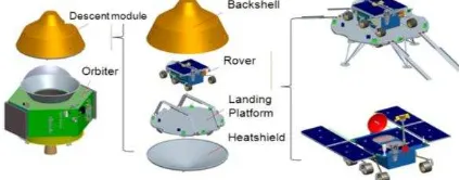
The probe will be launched by the CZ-5 vehicle. The launch period is in 2020. The spacecraft is composed of an orbiter and a descent module, which will complete the orbiting,landing and roving mission in one launch. The descent module is composed of a heatshield, a backshell, a landing platform and a rover. These major spacecraft components are shown in Figure 1.
Figure 1. The vehicle configuration
The orbiter will first carry the descent module into Martian orbit. When the landing time is reached, the descent module will be separated from the orbiter after the altitude of the perigee is decreased. When the top of the atmosphere is reached, the descent module will begin the EDL process and finally land on the surface of Mars safely.
After landing safely and the rover be released from the landing platform, the main science mission will start. The payload of the rover includes:
1) Terrain camera, 2) Sub-surface radar, 3) Multispectral camera, 4) Magnetometer, and 5) Anemometer.
The terrain camera will acquire images of the surrounding environment. The sub-surface radar may be used to obtain information of the internal structure of Mars. The multispectral camera can be used to analyse the components. The magnetometer will gauge the weak magnetic field of Mars. The anemometer will measure the atmospheric parameters.
The orbiter will complete the relay mission for the rover in the rely orbit. When the lifetime of the rover ends, the orbiter will at last enter into the remote sensing orbit to image the Martian surface for more than one year.
2. SELECTION OF THE LANDING SITE
The selection of accessible landing site is the primary step for surface exploration. The landing site is determined by both scientific goals and engineering constraints, of which the two factors should be well balanced and carefully decided. The engineering constraints are the key concerns of the mission. The Viking and Mars pathfinder (MPF) missions fully took the engineering constraints into consideration at the primary design phase and finally selected the probable landing sites.
There are various types of landforms on Mars, such as plains, craters, mountains, canyons, riverbeds, being similar to the Earth. The characteristics of the elevation, slope and relief are obvious, and the rocks are widely distributed. Besides, some areas are covered with thick dust arising from Mars storms. The atmosphere density of Mars is just 1% of the Earth’s.
The engineering constraints are mainly related to the atmosphere environments, surface characteristics of the landing sites, mission trajectory, etc. The surface characteristics include sunlight, thermal constraints, local elevation, rock distribution, dust thickness, slopes and relief that can affect the EDL safety and the rover mobility. Data acquired from previous Mars missions can be used to help selecting the possible landing sites.
The primary landing site is selected according to the constraints mentioned above. The primary selection phase follows the mission schedule, i.e. phase I - EDL and phase II - surface survey by a rover (Dong et al., 2015).
Phase I - EDL: The elevation, slopes and atmosphere density are the main factors to be considered. The determination of all the factors has the same principle, i.e., to select a region with low elevation. The available landing region with latitude higher than 5°N and the elevation lower than -3 km of the MOLA reference satisfies the EDL mission.
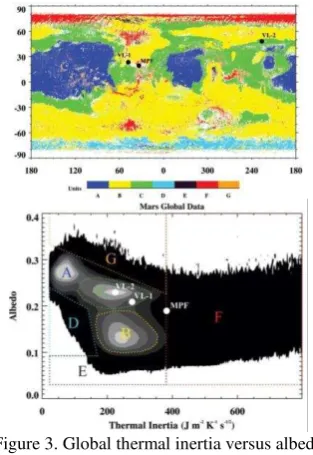
Phase II - Rover Survey: The environmental factors depend on the latitude. According to the local wind speed, lighting and temperature, the plain within the region of 5°N~30°N can be selected at primary. Three plains are selected according to elevation, slope and latitude, as shown in Figure 2. Region 1 (Red box in the left) is A- level (Figure 3) that has less thermal inertias, high reflectivity and thick dust. Region 2 (Black polygon in the middle) is mainly in B-level and Region 3 (Black polygon in the right) is C-level, thus Region 2 and 3 are selected. Region 2 has an abundance of the riverbeds and craters, and therefore the terrain is more complicated than Region 3. The elevation and slope in some areas may not be appropriate. Next we will select the landing sites from these two regions according to the science objectives and then analyse if the terrain is satisfied. Several landing ellipses are discussed
and will be selected before launch. The condition of the slope and rock abundance should be focused on in the selection of the landing ellipses.
Figure 2. Primary selected landing sites (MOLA Elevation)
Figure 3. Global thermal inertia versus albedo (Golombek, et al., 2012)
3. OVERVIEW OF THE EDL MISSION
There are normally three phases in the EDL, including the entry phase, parachute descent phase and powered descent phase (Prakash et al., 2008). The descent module will perform a lifting entry into the Martian atmosphere followed by a descent phase under a DGB parachute. A retro-engine will slow down the landing platform up to the point where a short free fall (or touch down) will be started. A crushable structure will absorb the remaining energy at landing.
3.1 Initial Condition
Entry Corridor is important for EDL. The selection of the FPA at EIP depends on many constraints, such as maximum heat flux, the altitude of parachute deployment and landing accuracy. The FPA is affected by many errors, such as the initial navigation error, orbital maneuver error, separation velocity error, etc.
An angle of attack is commanded that is similar to the trim angle before EDL. The commanded bank angle is set according to the initial entry orbital error.
3.2 Entry Phase
3.2.1Entry Trajectory Design
Both the ballistic entry and lifting entry had been used for entry phase. The lifting entry is better to guarantee the parachute deployment altitude, parachute deployment attack angle and landing accuracy for the descent module with high ballistic coefficient. It is necessary to maximize lift (it’s contributed by the trim angle of attack) (Figure 4) until the last possible crossrange to the target and command a bank reversal whenever the crossrange crosses a deadband threshold.
Figure 4.Ballistic versus Lifting Entry (Martin et al., 2015)
3.2.2Parachute Deployment Constraints
Constraints on the parachute deployment condition affect the guidance design in order to ensure adequate margins for the dispersed trajectories to meet the requirements.
1) Deployment altitude
As a propulsive descent system will be used after parachute deceleration, there is a timeline margin requirement, allowing sufficient time to be spent on the parachute, on the radar, and on the powered descent to land safely. This timeline is often roughly translated into a desired minimum chute deployment altitude relative to the surface. Normally the minimum altitude of 6~8km (Gavin and Craig, 2011) above the ground is necessary.
2) Mach Number
The Mach number at chute deployment has two effects on the chute: aeroheating and inflation dynamics. If the Mach number is too high, the chute may fail due to excessive heating at the stagnation point or experience a violent inflation that excessively loads the chute. The acceptable deploy Mach number range from 1.1 to 2.3 for MSL and Viking missions. Besides, the non-linear and non-stationary parachute forces increase exponentially above Mach 1.4 and becomes severe at Mach 2, which will cause the IMU saturation according to the ExoMars 2016 landing mishap (Nielsen, 2017).
3) Dynamic Pressure
Sufficient dynamic pressure at chute deployment is critical to ensuring inflation. If the dynamic pressure is too low, the resulting peak inflation loads may cause the chute to fail.
4) Chute Opening Loads
Thechuteloads that the entry vehicle and payload structure is designed for is yet another constraint on deploy conditions. The magnitude of the design chute opening load is a function of the chute drag that varies with Mach number, the inflation time of the chute and the dynamic pressure at the time of inflation.
5) Total Angle of Attack
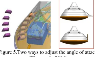
The parachute should be deployed in a low total angle of attack to avoid the line sail that will affect the asymmetric canopy inflation and cause the high dynamic oscillatory motion. Therefore the trim angle of attack should be zeroed out prior to parachute deployment. There are two ways (Figure 5) to implement the task: (i) Jettison of the internal entry balance masses to null the CoG-offset used for entry; and (ii) Trim-tab deployment to change the flow field.
MSL-I (Trim Tab)
外形 Figure 5.Two ways to adjust the angle of attack
(Kipp et al., 2006)
6) Mach number error
Parachute deployment is triggered based on Mach number. The probe estimates Mach number via correlation with navigated velocity and knowledge of the Martian atmosphere. It is necessary to bound the conditions that can be encountered on any given day within the landing window, while also considering all potential landing locations and parachute deployment altitudes.
Sound speed, which dictates conversion from wind relative velocity to Mach number, can vary as much as 1~2% (Kipp et al., 2006) of the inertial velocity. More importantly, winds, whether gusty or steady state, create a significant error between inertial and wind relative velocity that is not estimable during entry. Besides, the error estimates on navigated velocity are nearly 2% (Kipp et al., 2006) of the inertial velocity.
3.3 Parachute Descent Phase
For the previous successful Mars landing missions, the descent phase is based on a single stage supersonic DGB parachute. Following parachute deployment, the vehicle quickly decelerates to subsonic conditions. It will bring the descent module to vertical velocities of about 80~120 m/s. Thus the parachute system acts to burn over 75% of the remaining kinetic energy in just 1~2 min. During this phase, the frontshield is separated and the radar altimeter is activated in order to modify the IMU and trigger the backshield separation based on relative navigation with respect to the Martian surface.
Heatshield separation must satisfy two requirements: positive separation from the flight system with no re-contact and satisfactory distance to ensure no beam of the radar is obscured after activation. The separation mechanism needs to create initial separation velocity to avoid short-term re-contact. The sufficient ballistic coefficient difference should exist between the heatshield and the entry vehicle to result in continuous positive separation.
Figure 6.Heatshield separation (Taiszadeh et al., 2011)
3.4 Powered Descent Phase
Taking MSL as an example, the GNC software computes the appropriate altitude to separate from the backshell and start powered Descent, based on the estimated vertical velocity.
Backshell separation is followed by a short time of free fall to avoid short-term re-contact with the backshell. The lander needs to perform a divert maneuver to avoid the parachute/backshell from re-contacting with the lander (Figure 7).
When the altitude is reached before landing or the touching sensors work, the engine will be shut down. The crushable structure will absorb the remaining energy at landing.
Figure 7. Divert maneuver of MSL (Martin et al., 2015)
4. KEY CHALLENGES AND VERIFICATION OF THE MARS LANDING MISSION
4.1 Structure of the Descent Module
The structure of the descent module will protect the spacecraft from the intense heating, pressure, shear stresses, parachute mortaring force and deployment force experienced during entry. The chute opening loads are the main constraints for the structure design.
The frontshield is generally based on the typical 70° sphere-cone geometry, heritage of the Viking design and successfully adopted in the subsquent NASA missions to Mars. The PICA is selected as the forebody TPS. The TPS needs to be validated in the arcjet test.
Figure 8. Different descent module configuration of NASA’s Mars missions
4.2 Disk-Gap-Band Parachute
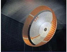
For the Mars atmosphere condition, design trades in NASA’s Mars landing missions, including options with two-stage parachutes, resulted in the baseline of a large supersonic disk-gap-band parachute (Figure 9). The diameter is the balance of the chute opening loads and deceleration requirement.
The parachute qualification program will be divided into four phases representing key functional risks: (i) mortar deployment, (ii) canopy inflation, (iii) supersonic performance, and (iv) subsonic performance. Each phase will contain specific components that are evaluated across various test venues.
Figure 9. A typical Disk-Gap-Band Parachute (Cruz et al., 2013)
The drag coefficients as a function of Mach number for the DGB parachute are tested via wind tunnel (Figure 10).
Figure 10.Parachute wind tunnel test
The rocket flight test (Figure 11) will supply the real Mach number and dynamic pressure environment to verify every phase, but it can not cover the extreme conditions due to the limited times. It is used to modify the core parameters of the parachute model. Therefore the CFD flow field simulation and dynamic calculation are vital for the parachute performance parameters.
Figure 11. An example of parachute flight test via rocket
4.3 Descent Inertial Measurement Unit
The EDL system contains the descent inertial measurement units (IMU) to propagate the spacecraft state. The IMU saturation which arises from the parachute deployment will affect the navigation error and may cause the mishap (such as The International Archives of the Photogrammetry, Remote Sensing and Spatial Information Sciences, Volume XLII-3/W1, 2017
the ExoMars 2016 mission). The IMU design must balance the measurement range and the accuracy. The navigation test will be performed under the vibration condition of the parachute deployment, separation trigger and powered descent to confirm the index.
4.4 Terminal Descent Radar
The radar consists of four radar beams canted at various angles at least, each of which independently measures the slant range and velocity. The radar is designed to operate over a wide range of conditions: from shortly after heat shield separation till the landing platform touches down on the ground.
The radar field test can be separated in two parts to cover the high to medium altitude and velocity ranges of operation. The test on a transport plane can cover the high altitude and velocity range that the TDR will operate after the heat shield separation. The test in a powered flight experiment will verify the low altitude and velocity envelope. A simulation testbed is also developed for product verification and end-to-end simulations.
4.5 EDL and Science Mission Communication
A suite of X-Band and UHF antennas are normally utilized to maintain communication both directly to Earth and to the orbiter during the EDL mission phase and science mission phase in NASA’s Mars landing missions.
During EDL, the descent module can only use the UHF link with the orbiter to return data back to Earth. After landing, the rover or the lander can communicate to Earth directly via X-Band antenna and establish the communication when the orbiter is in the Martian daytime.
The test examines not only the link from the spacecraft to the orbiter testbeds, but involving the respective ground data systems of the orbiter and the descent module and represent a high-fidelity test of the landing communication flow. The UHF and X-band functional and compatibility tests ensure that the communication system works and communicates properly with the orbiter and the ground station, respectively (Kornfeld et al., 2014).
4.6 Engines of the Platform
The main engine for reducing the final velocity basically needs to generate high and adjustable thrust. The hot-fire test, vibration and thermal vacuum test are necessary to verify the requirements.
The hot-fire test demonstrates that the engines satisfy the performance requirements (throttle range, specific impulse and thrust) after the vibration test. The thruster valve assembly is qualified separately and underwent functional tests between environmental testing. In addition to the development program, the model is constructed in the flight dynamic simulations to support the system test (Kornfeld et al., 2014).
4.7 Flight System Simulation and Test
The hardware and software of the spacecraft should be tested to validate the timeline and GNC behaviours, considering the specific environment on Mars. The test normally includes the following two types: (i) Real-time closed-loop execution of EDL hardware and software; and (ii) Functional test.
In addition to the flight mode test with most of the hardware, the dynamic simulation is also necessary for the design of the key parameters and FDIR. The model of the parachute deployment dynamics is very critical for the navigation, because the large canopy motion due to unsteady wake dynamics may cause large riser angle variations, including bridle slacking and asymmetric canopy inflation, which arise the IMU saturation (ExoMars 2016). In addition, the mathematical models of the critical hardware such as the IMU, the TDR, the thrusters and the main engine should also be established accurately to support the end-to-end simulations.
5. SUMMARY
This paper first introduces the profile of the Chinese Mars landing exploration mission. Then the procedures of the landing site selection are discussed, including the main engineering constraints. Following that, the EDL mission design and the challenges are discussed. The critical issues, corresponding simulation, and test of EDL can provide reference for the following Mars exploration missions.
REFERENCES
Cruz, J.R., D.D. Way, J.D. Dhidner, et al., 2013. Parachute Models Used in the Mars Science Laboratory Entry, Descent, and Landing Simulation. AIAA Aerodynamic Decelerator Systems.
Dong, J., L. Z. Meng, Y. Zhao, et al., 2015. Selection of the Martian Landing Site based on the Engineering Constraints, 66th International Astronautical Congress, Jerusalem, Israel.
Gavin, F. M., L. E. Craig, 2011. Entry Guidance for the 2011 Mars Science Laboratory Mission. AIAA-2011-6639
Golombek, M., J. Grant, D. Kipp, et al., 2012. Selection of the Mars Science Laboratory Landing Site. Space Sci Rev (2012) 170:641–737.
Kornfeld, R. P., R. Prakash, A. S. Devereaux, 2014. Verification and Validation of the Mars Science Laboratory/Curiosity Rover Entry, Descent, and Landing System. Journal of Spacecraft and Rockets, Vol. 51, No. 4.
Kipp, D., M. S. Martin, J. Essmiller, et al., 2006. Mars Science Laboratory Entry, Descent, and Landing Triggers. IEEEAC paper#1445.
Martin, M.S., G.F. Mendeck, P.B. Brugarolas, et al., 2015. In-flight experience of the Mars Science Laboratory Guidance, Navigation and Control system for Entry, Descent, and Landing.CEAS Space J(2015) 7:119-142.
Nielsen, T. T., 2017. EXOMARS 2016-Schiaparelli Anomaly Inquiry.
Prakash, R., P. D. Burkhart, A. Chen, et al., 2008. Mars Science Laboratory Entry, Descent, and Landing System Overview. IEEEAC paper#1531.
Taiszadeh, B., P. Desai, R. Michelltree, 2011. Mars Exploration Rover Heat Shield Recontact Analysis. AIAA-2011-2584. The International Archives of the Photogrammetry, Remote Sensing and Spatial Information Sciences, Volume XLII-3/W1, 2017