RFM-BASED BLOCK ADJUSTMENT FOR SPACEBORNE IMAGES
WITH WEAK CONVERGENCE GEOMETRY
C. Q. Chenga,* , J. X. Zhanga, G. M. Huanga
a Institute of Photogrammetry and Remote Sensing,Chinese Academy of Surveying and Mapping. Lianhuachixi Road, Beijing, (cspring*, Zhangjx, Huang.guoman)@casm.ac.cn
Working Group VII/6
KEY WORDS:Block Adjustment,Weak Convergence geometry, Image Positioning, Multi-Source Image.
ABSTRACT:
Block adjustment is one of the most important processing steps in topographic mapping. In order to achieve precise 3D photogrammetry points, the ratio of base-to-height(RBH) or the forward intersection angle(FIA) of stereo images should meet the requirement of specifications for topographic maps when the block images are used. In some fields, overlaps and ratios of base-to-height are often ignored, no gaps among the images are the basic requirements for block images. In this study we give a method to detect the forward intersection angle for homonymous points with RPCs, and create a indicator angler to reflect the level of weak convergence. In order to achieve stable and precise solver for block adjustment under the condition of weak convergence, this paper take the elevation value interpolated from DEM as observed values with errors, combine the height value and measured image coordinates to build adjustment model. The model can be steady solved in ill-pose situation and have little effects from the DEM errors. the model and the methods are validated by simulation and real data including optical ZY1-02C and TerraSAR images.
1 INTRODUCTION
1.1 General Instructions
Classic block adjustment model are often build for obtaining 3D photogrammetry points to reduce the field work of ground control point measurement . So before obtaining images the paths and shotting parameters must be designed in detail. In order to avoid the weak convergence the ratio of base-to-height or the intersection angle of stereo images must meet the requirement for topography.
Today the motivation and image data for the geometry processing are various. Obtaining 3D photogrammetry points is not the only purpose for block adjustment. When the orientation parameters of block images are refined with sparse ground GCPs the ortho-rectification batch program can easily be build for block images. Even on purpose of obtaining precise 3D points the weak convergence geometry may happen in some area such as
With the rapid development of multi-source sensor technology, combined positioning with multi-source images are more popular. For geometry process with RFM have no bearing on specially appointed sensor, RFM is the first selection for multi-source spaceborne images. If we have multi-multi-source images with stable and weak convergence geometry in different area the 3D point with high accuracy can still have opporunity to obtained. So it is worthwhile to study on block adjustment model suiting for weak convergence geometry and multi-source spaceborne images.
RFM is a replacement for rigorous sensor model,which has arised since 1980s(Paderes,1989) and not widely applied and studied until RPCs used as Ikonos auxiliary data. In 1999 Tao
and Hu (Tao and Hu,1999) develop an investigation on the Rational Function Model and its application in rectification. On the Conference of 2002 ISPRS Dial(Dial,2002) and Fraser(Fraser,2002) and Tao (Tao ,2002) Studied the orientation model of RFM. The bias-compensation model in image space was popularized after the Conference. Zhang(Zhang,2008) conduct a study of the RPC model of TerraSAR-X and COSMO-SKYMED SAR imagery. Today RFM can suit almost all spaceborne optical and SAR images.
Aiming at image positioning with weak convergence geometry,Zhang et al.(2012) proposed an algorithm of bundle block adjustment with a weakly connected condition for aerial imagery. Tee-Ann Teo(Teo,2010)
Use the digital elevation
model (DEM) as the elevation control
and indicate the method can significantly improve the geometric accuracy as well as the geometric discrepancies between images. Taoyang Wang(Wang, 2014) proposes a strategy that uses a planar block adjustment method to solve the orientation parameters of all satellite images,and then each satellite image is orthorectified. The key technology is take height in RFM as known parameter which can be extracted from DEM.In weak convergence geometry condition, above mentioned methods take elevation from DEM as known height value in RFM, the unknowns of ground point coordinate recede from three to 2, so the ill-pose in forward intersection can be avoid. The method can used in the case the intersection angle is very small. When intersection angle between weak convergence and stable convergence, such as 2o~10o, the errors from DEM would greatly affect the image orientation. The height errors in RFM contains DEM measurement error, GSD errors, elevation anomaly, and the difference between DSM and DEM. The value of height errors could reach to 100m about in mountainous and city area.
This contribution has been peer-reviewed.
Intersection angle is the corner between vectors of ground point to two sensor position where the stereo images are generated. For the assistant data of images are RPCs only, it is difficult to obtain the sensor location of shoting time. Untill now the study of geometry processing with weak convergence are mainly focus on optical images. SAR images or SAR and optical images with weak convergence are not payed enough attention to. When mulit-source images are organized to conduct together, the effect of forward intersection angle cann’t indicate the degree of weak convergence because the range of intersection angle of weak convergence geometry are different. So it is necessary to build a parameter which can indicate the degree of weak convergence for different image.
2 CALCULATION OF FORWARD INTERSECTION ANGLE WITH RPC AND WEAK CONVERGENCE GEOMETRY DETERMINING
Forward intersection angle or ratio of base-to-height is the foundation to determine whether the 3D point geometry is belong to weak intersection. In this paper we calculate the angle using track vector of ground point of homonymous point in adjacent images. We also design a indicator angle to reflect the degree of weak convergence geometry for different source image set.
2.1 Calculation of Forward Intersection angle
RFM is one kind of generalized sensor model used as an alternative to the rigorous physical model, in which image pixel coordinate (R,C) are expressed as the ratios of polynomials of ground coordinates(L,B,H). the algorithm of the RPC estimator and the technique for determining its coefficients have been described in detail by Zhang(2008). The image and ground coordinate are usually normalized through offset and scale to fit the range from -1.0 to 1.0. The normalized image coordinate(Rn,Cn) and the corresponding normalized ground coordinate(Pn,Ln,Hn) can be presented as follows:
1
Where Pi(i=1,2,3,4)are the terms of the third-order polynomial of (Pn,Ln,Hn); (Pn,Ln,Hn) are the normalized ground coordinate; (Rn,Cn) are the normalized image coordinate; (Poff,Loff,Hoff)are offset values for ground point coordinate, (Roff,Coff) are offset values for image point coordinate; (Pscale, Lscale, Hscale)are scale values for ground point coordinate, (Rscale,Cscale) are scale values for image point coordinate.aij,bij,cij,dij(i=1,2,3,4;j=1,2…20)
are coefficient of polynomialPi.
For most image auxiliary with RPC don’t contain ephemeris data, it is hardly to calculate the satellite location at shotting time. RFM is a replacement of rigorous sensor model and have an equal positioning result with the model. when the height in the RFM is given different, the trajectory of the ground point is same as from the rigorous camera model. If the track vector are
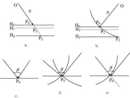
calculate using RPC at near of real height, the intersection vector can be calculated. The forward intersection angle corresponding to the homonymous points also can be obtained. The principle is shown as Fig1.
Fig 1. Relation among incidence vector, trajectory vector and FIA(a)incidence vector and trajectory vector of optical imagery;(b) incidence vector and trajectory vector of SAR imagery; (c) FIA between optical and optical images;(d) FIA between SAR and SAR images; (e) FIA between optical and SAR images.
According to the definition of the FIA, the calculation procedure is as following:
(a) Calculate the ground point coordinate values of longitude and latitude using RPCs in which the value H0 of height is extracted from DEM (SRTM);
(b) Given the height parameter new values, that means H1=H0 -1 and H2=H0-1000, recalculate the coordinates of ground point P1(B1,L1,H1)and P2(B2,L2,H2);
(c) Translate the geodetic coordinate into Geocentric rectangular coordinate(ECEF), get the value of coordinate in ECEF and mark them as P0(X0,Y0,Z0), P1(X1,Y1,Z1),
(d) Calculate the intersection vector. For optical images the intersection vector is same as track vector, that means
P P0 1 . For SAR images the intersection vector is perpendicular to track vector, that means
OP P P P P P P0 0 1(0 1 0 2) ;
(e) Calculate the forward intersection angle according to the following formula:
arccos / | | | |
1 2 1 2 (2)
Where 1、 2 are intersection vector of homonymous point from
over coverage images computed by above formula in step (d). (f)By above steps intersection angle can be calculated for positioning with optical images, SAR images or combined SAR and optical images.
2.2 Qualitative analysis for image positioning with different sensor images
For image positioning only with optical images or only with SAR images, the more FIA or ratio of base-to-height is greater, the convergence is more stable. On the contrary the convergence geometry with SAR and Optical images is at the most weak condition when FIA reach near 90oand at the most stable condition when FIA reach near 0o. So the same value of FIA have different affection to different image combination positioning.
In the positioning process with spaceborne images the errors from orbit and attitude measurement are systematic and errors from image coordinate measurement are usually random. The systematic errors can be easily eliminated by adjustment,while random errors of image point measurement are hardly to remove. For optical sensor the errors of image point coordinate may affect the light of view of CCD detector. For SAR images the errors may affect the sensor location and distance between satellite and ground point. When the image point errors affect the view vector or the distance , the positioning errors happened. In Fig3 S,S1,S2 are sensor location, S2 is more far from S than S1 from S, that means the forward intersection angle or ratio of base-to-height of stereo images obtaining from S2-S is bigger than from S1-S. The ground point P is the true location corresponding to the stereo homonymous image points. When same measurement error add to point coordinate of image from S, new light vector or new range with error is calculated. When the new vector or new range sphere with error intersect with light vector or range sphere from S1 or S2, new 3D ground point P1 and P2 can recalculated. The deviations from P1 to P and P2 to P are different, they reflect the positioning errors of stereo images with different FIA or RBH. Fig 2 respectively shows(a)the intersection only with optical images,(b)the intersection only with SAR images,(c)the intersection with optical and SAR images and errors applied to optical image,(d)the intersection with optical and SAR images and errors applied to SAR image. The deviated P1 is corresponding to stereo images with little FIA or RBH and P2 is corresponding to images with large FIA or RBH. We can see in Fig3(a)(b) the deviation of P1 is larger than that of P2, and in (c)(d) the deviation of P1 is smaller than that of P2. So FIA or RBH has different affection to different stereo images with SAR or optical image combinations.
Fig2.Effect of weak convergence geometry on imagery positioning error.(a)OPT images;(b)SAR images;(c)SAR and
Optical images(error in SAR image);(d)SAR and Optical images(error in optical image).
2.3 Weak Convergence Geometry identification
Image stereo positioning with weak convergence are easily fail. It is necessary to find out the homonymous image points with weak convergence geometry. For the value of FIA or RBH are not always consist with the stability of different stereo images, building a indicator parameter which can reflect the stability of all stereo images is meritorious. In this paper, we take the intersection angle of ground point track vector corresponding to homonymous image points as indicator angle to indicate the stability of 3D positioning. In Fig 2 the intersection angle between PP1
and PP2 are indicator angle for stereo point of
images from S1 and S2 respectively. If their track vectors near the altitude are marked as 1and2, the intersection angle θ of trace vectors is as following:
arccos
When θ∈(0,90],the more θ is little, the more weak convergence
geometry has. While θ∈[90,180),the larger θ is , the more weak
convergence has. The most stable geometry is θ coming near 90 degree. We defineδwhich always belong to range from 0 to 90 as indicator angle for stability of convergence geometry.
90 90
(4)
The stability always changes with indicator angle δ in same direction. For optical images the FIA are usually smaller than 90o, so the indicator angle is equal to FIA when stereo positioning only with optical images.
3. POSITIONING WITH RESTRICTION OF DEM ELEVATION
In order to build the error equations of image point coordinate measurement, image point coordinates can be expressed by ground point coordinate(P,L,H):
off scale off scale scale
scale off
off scale off scale scale
off scale off scale scale
scale
The orientation of RFM can be applied in image space or in object space. The process can be simplified if orientating in image space. Bias compensation in image space contains three case. Translation model is applied when a single additional GCP is used for resolving the two unknowns, shift model is applied when two additional GCPs are used for resolving the four unknowns, and affine model is applied when no less than 3 GCPs are used for resolving the six unknowns. If affine model is selected and unknown parameters are(m0,m1,m2,n0,n1,n2), the equations can be written as:
0 0 1 2 11 21 31
Where VR,VCare error increments for image point measurement; (R0)(C0) are calculated values with primary RPCs, R,C are observed image coordinates,(△P,△L,△H)are increment
unknowns of ground point which might be leave out when the ground point are GCP with high accuracy. PR,PCare weights for observed image point coordinates.
This contribution has been peer-reviewed.
For each image point two equations as formula(6) can be build. Equations for all image points can be shortened as:
V AX L P (7)
Where V is error vector of image point coordinates, A is designed matrix, X is unknown vector, L is constant vector, P is weight matrix.
Ill-position of the equations resolve may happen if the surveying area has small indicator angle images and the resolution of 3D ground point would diverge. Public geographic data include global DOM and global DEM can be freely download. If the height from public DEM such as SRTM which the accuracy may be far more higher than that from weak convergence point used as auxiliary information in the adjustment model, the stability of the resolution may be improved. Here we take the heights from public DEM as one kind of observing value with certain degree accuracy, and introduced them into the orientation model by combined adjustment with images and height observing values. The equations (7) added by errors of height as following:
H H H
v H l p (8)
Where vH is the error increment for height, which can be set according to the accuracy of DEM.
When the elevation in RFM is precise, the PH is large, the correction of △H is small, and the errors in image point
coordinate is easy to be find out after adjustment calculation . On the contrary the errors of image point are difficult to discover especially in parallax direction. So the wrong checking and accuracy guarantee for tie points with weak convergence before adjustment is necessary when the height is not precise.
4. 4 TEST AND APPLICATION
4.1 Simulation tests on relation of indicator angles and positioning errors
For RFM has an equal accuracy with rigorous model. In order to simply the simulation, we calculate positioning errors with rigorous geometry using simulated parameter values. The heights of satellites are set to 650km, the attitudes of satellites are all set to 0 degree, the image resolutions are about 1m( slant range for SAR images), the errors of image point coordinate measurement are 1 pixel. For the size of 3D positioning errors in height direction is at the largest when the homonymous image point errors is at the parallax direction with +1 pixel and -1 pixel respectively. Here we suppose the system errors in images have been eliminate by adjustment. The random errors from image point measurement which can’t be effectively remove would affect the result of positioning.
Simulation process mainly contains three steps. Firstly a pair of
theoretical image point coordinates are calculated according to the given photography parameters, which include the ground point 3D coordinates, the sensor locations computing using known FIA and satellite heights and attitudes. Then add the errors to the image point coordinates and intersect the 3D ground point coordinate with the simulated image point and original shotting parameters. At last the 3D positioning errors can be easily obtained, and the positioning error according to each indicator angle or indicator angle can be list.
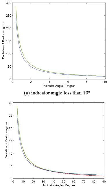
The theoretical ground point coordinate are set to (0,0,0). In order to get different FIA the sensor S1 and S2 are depart from each other in opposite direction at same velocity. The fig shows the trend of positioning errors with indicator angles for optical stereo images(red), SAR stereo images(green) and combination stereo images(blue). (a) indicator angle less than 10o
0 10 20 30 40 50 60 70 80 90
(b) indicator angle between 0oand 90o Fig 3. Positioning errors changing with indicator angles.
Table 1. is statistics for optical stereo positioning errors and their indicator angles.
Indicator angle(deg) 0.1 0.5 1.0 1.5 2.0 3.0 5.0 8.0 10.0 15.0 20 30 40 50 60
Positioning errors(m) 1147 229 114 76.4 57.3 38.2 22.9 14.3 11.4 7.6 5.6 3.7 2.7 2.1 1.7
From the curve graph and table we can see:
(a)For optical stereo images,SAR stereo images and optical and SAR combination stereo images, the positioning errors trends corresponding to indicator angles are similar to each other. The errors are inversely proportional to the angles. The indicator angle can reflect the stability of multi-source image 3D positioning.
(b)The size of errors in height direction are no larger than that of positioning errors in fig and table 1 considering the
(c)From the common geometry of image 3D positioning, the intersection between nadir optical images or between SAR images with same looking direction is easily produce weak convergence. While for the combination stereo of optical and SAR images, indicator angles are often far from 0 degree, so combined positioning with SAR and optical images has smaller probability to be weak convergence condition than same nature images.
4.2 SAR and Optical Positioning with weak convergence geometry
(1)SAR imagery Positioning
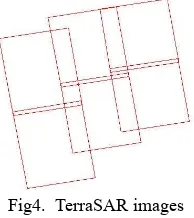
Six scenes of TerraSAR images(slant range resolution is about 1m) captured in 2013 was used in this test. The images are in North of Hebei province, china, and the elevation range is from 0 to 1500 m(Fig 3). There are 117 GPS-surveyed GCPs in the range of block images. Different numbers of points varying from 0 to 10 were selected from the 117 points as GCPs(1 GCPcase: placed on center of the area; 4GCPs case: placed on four corner; 8 and 20 GCPs case: evenly distributed) and evenly distributed on the images, while the rest were treated as check-points. All image points are measured by manual ways. The initial height values of homonymous image tie points with weak convergence geometry were set as SRTM elevation and average elevation(700m) of the surveying area. And the accuracy is set to 20m and half of the maximum elevation of the area respectly. The original auxiliary orientation parameters are imaging and ephemeris data which have been translated to RPC before test.The results are list on the table 3.
Fig4. TerraSAR images
Table 2. Statistics for positioning accuracy of TerraSAR images in Line and Sample direction(units: pixel)
GCP Number 0 1 4 8 20
Elevation from SRTM
TP_L 0.68 0.74 0.79 0.80 0.90
TP_S 0.43 0.44 0.49 0.53 0.61
GCP_L 0.03 0.39 1.03 1.15
GCP_S 0.01 0.41 1.07 1.20
CP_L 1.59 1.53 1.45 1.31 1.20
CP_S 1.77 1.49 1.38 1.42 1.27
Average
elevation TP_L 0.61 0.69 0.72 0.76 0.87
TP_S 0.37 0.38 0.41 0.46 0.48
GCP_L 0.03 0.39 1.03 1.14
GCP_S 0.01 0.40 1.06 1.20
CP_L 1.61 1.55 1.46 1.32 1.20
CP_S 1.79 1.50 1.40 1.43 1.29
(2)Optical imagery Positioning
ZY-1 02C is a Chinese satellite, which has filled the domestic blank of high resolution, was installed with PAN, Multi-spectrum and high resolution sensors. In this paper fifteen scenes of 02C-HR images and one scene of 02C-PAN image in Gansu province , west China, whose elevation range is from 600 to 1600m, was used to represent optical images for test. The resolution of 02C HR imagery is 2.36m, and the resolution of PAN imagery is 5.0m.
Fig5. ZY1-02C images
Table 3. Statistics for positioning accuracy of ZY1-02C images in Line and Sample direction(units: pixel)
GCP Number 0 10 50 100 300
Elevation from SRTM
TP_L 1.3 1.3 1.4 1.4 1.5
TP_S 1.1 1.2 1.2 1.3 1.3
GCP_L 0.9 1.5 1.9 2.5
GCP_S 0.7 1.3 2.0 2.8
CP_L 14.7 5.8 3.9 3.0 2.6
CP_S 6.5 4.9 3.6 3.2 2.9
Average
elevation TP_L 1.1 1.2 1.2 1.3 1.3
TP_S 0.8 0.9 1.0 1.2 1.2
GCP_L 0.8 1.4 1.9 2.6
GCP_S 0.7 1.3 1.9 2.7
CP_L 14.8 5.9 4.0 3.1 2.7
CP_S 6.6 5.0 3.6 3.2 2.9
From the SAR and Optical image positioning with weak convergence geometry we can see:
(a) For TerraSAR imagery, positioning without GCP can obtain high accuracy because of the precise original auxiliary data, and the improvement is not obvious with sparse GCP because the measurement errors of image points and their corresponding GPS-surveyed ground points can’t be ignored.
(b)The accuracy and maximum error of TPs are both decreased with average elevation instead of SRTM elevation, while the accuracy and maximum from GCPs and CPs have no obvious change.
(c)For 02C optical images, the positioning accuracy without GCP is poor, but the relative accuracy of TPs are still good. Along with the increasement of GCP number the positioning accuracy of CPs promotes more slowly than TerraSAR images.
5. CONCLUSION
Mainly for the different level of weak convergence of forward intersection and different accuracy of assistant DEM , this paper
This contribution has been peer-reviewed.
take the elevation from External DEM as observed values with errors and add their error equation to the image point error equation group. The model can decrease the image tie point errors caused by elevation error when the convergence is not weak enough and elevation is not precise enough. Tests with simulation and real image data show the method can be more suitable for arbitrary image combination and can be independent of external high accuracy DEM .
ACKNOWLEDGMENTS
This work was supported by Land and Resources research special funds for public welfare projects(201411119-2).
REFERENCES
Paderes, Jr, F.C., E.M. Mikhail, and J.A. Fagerman, 1989. Batch and on-line evaluation of stereo SPOT imagery, Proceedings of the ASPRS-ACSM Convention, 02-07 April, Baltimore, Maryland, pp. 31-40.
C.V.Tao, and Y.Hu.2001.Investigation on the Rational Function Model, Proceedings of 2000 ASPRS Annual Convention (CD ROM), 24-26 May, Washington, D.C..
C.V. Tao, and Y. Hu.2001.Study of the rational function model for image rectification, Proceedings of Canadian Conference on Remote Sensing, 22-25 August, Victoria, BC, Canada, pp. 55-64.
Fraser C, Hanley H, Yamakawa T, 2002. High-precision geopositioning from Ikonos Satellite Imagery. Proceedings of ASCM-APSRS Annual Convention, Washington DC,April 19-26, CD ROM.
Dial G, and Grodecki, J. 2002. Block Adjustment with Rational Polynomial Camerca Models. Proceedings of ASCM-APSRS Annual Convention, Washington DC, April 19-26, CD ROM. G.Zhang and X.Y.Zhu,”A Study of the RPC model of TerraSAR-X and COSMO-SKYMED SAR imagery”,in Proc.Int.Arch.Photogramm.,Remote Sens.Spatial Inf.Sci,Beijing,China,2008,pp.321-324.
Zhang,Y.,X.Xiong, X.Shen,and Z.Ji, 2012.Bundle block adjustment of weakly connected aerial imagery, Photogrammetric Engineering & Remote Sensing,78(9):983-989.
Tee-Ann Teo, Liang-Chien Chen, Chien-Liang Liu,Yi-Chung Tung,Wan-Yu Wu. DEM-Aided Block Adjustment for Satellite Images With Weak Convergence Geometry. IEEE Geoscience and Remote Sensing Society.2010.48(4):1907-1918.