The Influence of Bearing Stiffeners to
Double - Symmetrical
I-Section
’s Torsion
Stiffness, an Analytical Approach
S. Tudjono. A.L. Han
Faculty of Engineering, Diponegoro University, Jalan Prof. Soedarto, SH, Tembalang, Semarang 50235, Indonesia
[email protected],[email protected]
Tel: +62 24 70779696; Fax: +62 24 7460053 ABSTRACT
Bearing Stiffeners are preventing web-local-buckling and reinforcing this section for point-loads and shear-forces. This paper discusses bearing stiffeners’ contribution in enhancing double-symmetric I-sections’ torsion capacity. Based on the Saint Venant’s formula torsion stresses are carried solemnly by the section, neglecting the stiffeners’ contribution. However, these stiffeners exhibit significant rotational deformation with the I-section in warping, indicating development of internal forces, restraining the
warping. Therefore, the negligence of stiffeners’ contribution in Saint Venant’s torsion formulahas to be revised.
Torsions within the stiffeners are the Saint Venant’s and torsion-shear-stresses induced by bending. Assuming out-of-plane stresses neglected, normal and bending-shear torsion stresses are zero, leaving only the Saint Venant’s. From equilibrium at the stiffener –to-flange’s-joint, the stiffeners’ natural boundary conditions equation can be obtained. Their presence leads to a rotational-torsion function differentiation along the beam, between stiffeners. But since all points have identical internal torsion forces, the disturbed differential torsion warping equations are identical. Using the geometrical and natural boundary conditions equation the mathematical-rotational-torsion-solution for each field along the beam is obtained.
It can be concluded that the member’s torsion stiffness increases approaching to linear while the increment will approach a hyperbola as a function of stiffeners’ number and thickness, respectively.
Keywords: stiffeners, double-symmetric I-section, torsion, warping
I. Introduction
In design it is assumed that shear forces acting on an I-section are carried by the web only. When exceeding the web’s shear capacity, reinforcement by bearing stiffeners are used so that the resultant shear capacity of stiffener and the web will be greater than or equal to the factored shear force.
The opposite warping of the two flanges will produce an orthogonal rotation of the bearing stiffeners. This bearing stiffener’s rotation proves the presence of an internal torsion force restraining the warping.
This paper will analyze the significance of bearing stiffeners’ contribution to the torsion behavior of I-sections.
2. Methods
For evaluating the bearing stiffener’s contribution in carrying torsion forces, the finite element method can be used. However, this paper will approach the issue analytically
For the case of a section with restrained warping solved by the analytical method, two major points has to be explained, i.e.
1. The analytical formulation of the relationship between the stiffeners’ internal forces to the section’s torsion deformation
2. The section’s natural boundaries at the location of stiffeners
For analysis’ purposes the following assumptions were used: the material is perfectly elastic; the behavior is based on Navier’s hypothesis; the plates’ thickness are considered small if compared to all other dimensions; overlapping of connected plate-elements is neglected; all the out-of-plane stresses are ignore.
Internal forces in the bearing stiffener
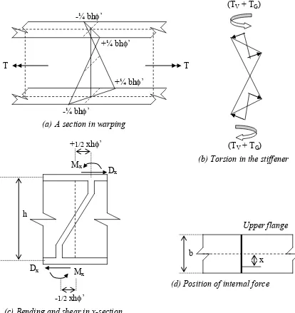
Due to warping of the bearing stiffener, the flanges will rotate in an opposite direction as shown in figure 1 (a).
The flange tips will undergo warping of respectively + ¼ bh’ and - ¼ bh’. The flange will rotate with an angle of to its original position.
Considering the rotation per-unit-length of the element to be ’, a Saint Venant’s
torsion of Tv will act on the bearing stiffener.
Saint Venant’s torsion will induce shear stresses parallel and perpendicular to the
The bending moment Mx in the bearing stiffener will generate a normal stress
perpendicular to the flange. Following the assumption that all out-of-plane
stresses are neglected,
Normal stresses perpendicular to the flange are ignored, and therefore the bending moment in the stiffeners will be zero and TGwillbe vanished.
The Saint Venant’s shear stress perpendicular to the flange will decrease
to zero in the direction of the flange’s outer fibres.
Figure 2. Moment equilibrium at the stiffener –to-flange’s-joint
ML MR TV
(a) A section in warping
-¼ bh’
+¼ bh’ -¼ bh’
+¼ bh’
T T
(TV + TG)
(TV + TG)
(b) Torsion in the stiffener
h
+1/2 xh’
-1/2 xh’ Mx
Mx
Dx
Dx
(c) Bending and shear in x-section
b
x
Upper flange
(d) Position of internal force
From the flange’s moment equilibrium at the position of the stiffener, the following equation (4) can be written.
Since the equilibrium equation becomes:
This is the equation of natural boundary conditions 3. Analysis
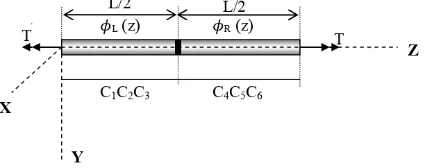
3.1. A beam with one bearing stiffener at mid- point
Figure 3. Beam with one bearing stiffener at mid-point
All torsion elements with restrained warping will have the following rotation equation.
Given the general solution as:
The stiffener at mid-point will divide the into two segments, L and R each having a different integration constant
Where:
From the natural and geometric boundaries for a simply supported beam theintegration-constants can be calculated.
By substituting the value of z = L into the section’s rotation equation we will achieve:
L/2
X
Z
Y
�L (z)
C1C2C3
T T
L/2
C4C5C6
The first term of the equation represents the bearing stiffener’s contribution and the second one is the Saint Venant’s torsion. It is demonstrated that one bearing stiffener at mid-point reduce the section’s rotation. It can be seen that the bearing stiffener contributes to the beam’s torsion stiffness.
3.2. A beam with multiple bearing stiffeners.
In the case of a beam with n number of bearing stiffeners, the beam will be divided in (n+1) fields, each having a different rotation function. Integrating the differential equation 5a, 3(n+1) integration-constants for every section will be produced. By applying the geometric and natural boundary conditions at the supports and the bearing stiffeners, these 3(n+1) constants can be derived.
Figure 4. A beam with multiple stiffeners
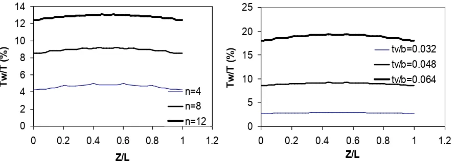
From analysis a curve as a function of the section’s rotation, thickness and
Figure 5. Torsion-warping contribution - stiffener’s number relationship for tv/b = 0.048
The torsion-warping contribution in carrying torsion as a function number of stiffeners is shown in figure 5, while the contribution of BS thickness can be seen in figure 6. The horizontal axis is the ratio between the stiffener’s positions to the
beam’s length, and the vertical axis represents the warping to
torsion-force ratio. The influence of the torsion-warping is more significant approaching mid-point, and increases approaching the position of stiffener.
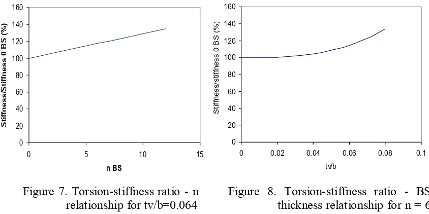
The torsion-stiffness ratio increase for multiple stiffeners with a ratio tv/b = 0.064 is shown in figure 7, while figure 8 shows the torsion-stiffness ratio increase as a function of bearing stiffener’s tickness.
4. Result and Conclusion
From the analytical analysis of a WF 250 x 125 section having equally distributed bearing stiffeners along the beam, the following can be concluded;
1. The torsion-warping contribution increases toward mid-point of the beam 2. The torsion-warping contribution increases in the direction of the bearing
stiffeners
3. The member’s torsion stiffness increases approaching to linear as a function of the stiffeners’ number n
4. The member’s torsion stiffness increment will approach a hyperbola as a function of stiffeners’ thickness
5. References
1. Bleich, F., and Bleich, H.H., 1952, Buckling Strength of Metal Structures, McGraw - Hill, New York.
2. Chajes, A., 1970, “Principles of Structural Stability Theory”, Prentice Hall, New Jersey. 3. Salmon, CG, and Johnson, JE, 1996, “Steel Structures Design and Behavior”, Harper
Collins College Publishers, New York. Figure 7. Torsion-stiffness ratio - n
relationship for tv/b=0.064
4. Sri Tudjono, 2005, “Kajian Pengaruh Pengaku Vertikal Terhadap Beban Kritis Tekuk Lateral Torsi Balok Baja Berprofil I” (The influence of vertical stiffeners to the critical lateral torsion buckling of I-sections), PhD Dissertation, ITB, Bandung.
5. Galambos, T.V., Lin, F.J. and Johnston, B.G., 2002, “Basic Steel Design with LRFD”, Prentice Hall, NJ.
6. Galambos, T.V, 1998, “Stability Design Criteria for Metal Structures”, Fifth Edition, John Wiley and Sons Inc, New York.
7. Polyzois, D, 1992, “Advance Steel Structures and Behavior”, Lecture Notes, Civil Engineering Department, Manitoba University, Canada.
Nomenclature (Notation)
: Angle of section rotation to its reference position T : Torsion Moment
E : Modulus of Elasticity G : Modulus of Rigidity L : Length of beam BS : Bearing Stiffener b : Width of flange
h : Distance from the centroid of the upper flange to the bottom flange of an I section tv : Vertical bearing stiffeners thickness
α : Angle of flange section rotation at bearing stiffener : Angle of bearing stiffeners rotation
IS : Flange’s moment of inertia with respect to the section’s week axis IW : Warping constant
TG : Stiffeners torsion moment resulting from shear bending Tv : St. Venant orsion moment of bearing stiffeners
Tw : Torsion warping moment of section JPV : Torsion constant of bearing stiffener J : Torsion constant of section