Architecting the Telecommunication Evolution: Toward Converged Network Services
Vijay K. Gurbani and Xian-He Sun ISBN: 0-8493-9567-4 Architectures for a New Breed of Applications
Seng Loke
ISBN: 0-8493-7255-0
Fundamentals of DSL Technology Philip Golden, Herve Dedieu, Krista S Jacobsen ISBN: 0-8493-1913-7
Introduction to Mobile Communications: Technology,, Services, Markets
Tony Wakefield, Dave McNally, David Bowler, Alan Mayne Jelena Misic and Vojislav B Misic ISBN: 0-8493-3157-9
Yan Zhang, Honglin Hu, and Masayuki Fujise ISBN: 0-8493-8036-7
G.S.V. Radha Krishna Rao, G. Radhamani ISBN: 0-8493-7059-0
WiMAX: Taking Wireless to the MAX Deepak Pareek
ISBN: 0-8493-7186-4
Wireless Mesh Networking: Architectures, Protocols and Standards
Yan Zhang, Jijun Luo and Honglin Hu ISBN: 0-8493-7399-9
New York London
TECHNOLOGIES
Boca Raton, FL 33487-2742
© 2008 by Taylor & Francis Group, LLC
Auerbach is an imprint of Taylor & Francis Group, an Informa business
No claim to original U.S. Government works
Printed in the United States of America on acid-free paper 10 9 8 7 6 5 4 3 2 1
International Standard Book Number-13: 978-0-8493-8057-0 (Hardcover)
This book contains information obtained from authentic and highly regarded sources. Reprinted material is quoted with permission, and sources are indicated. A wide variety of references are listed. Reasonable efforts have been made to publish reliable data and information, but the author and the publisher cannot assume responsibility for the validity of all materials or for the consequences of their use.
No part of this book may be reprinted, reproduced, transmitted, or utilized in any form by any electronic, mechanical, or other means, now known or hereafter invented, including photocopying, microfilming, and recording, or in any informa-tion storage or retrieval system, without written permission from the publishers.
For permission to photocopy or use material electronically from this work, please access www.copyright.com (http:// www.copyright.com/) or contact the Copyright Clearance Center, Inc. (CCC) 222 Rosewood Drive, Danvers, MA 01923, 978-750-8400. CCC is a not-for-profit organization that provides licenses and registration for a variety of users. For orga-nizations that have been granted a photocopy license by the CCC, a separate system of payment has been arranged.
Trademark Notice: Product or corporate names may be trademarks or registered trademarks, and are used only for identification and explanation without intent to infringe.
Library of Congress Cataloging-in-Publication Data
Wu, Weidong.
Packet forwarding technologies / by Weidong Wu. p. cm.
Includes bibliographical references and index. ISBN-13: 978-0-8493-8057-0
ISBN-10: 0-8493-8057-X
1. Packet switching (Data transmission) 2. Routers (Computer networks) I. Title.
TK5105.W83 2008
621.39’81--dc22 2007026355
Visit the Taylor & Francis Web site at http://www.taylorandfrancis.com
and the Auerbach Web site at
v
Contents
Preface ... xiii
Acknowledgments ... xv
About the Author ... xvii
Chapter 1 Introduction ... 1
1.1 Introduction ... 1
1.2 Concept of Routers ... 2
1.3 Basic Functionalities of Routers ... 2
1.3.1 Route Processing ... 2
1.3.2 Packet Forwarding ... 4
1.3.3 Router Special Services ... 5
1.4 Evolution of Router Architecture ... 7
1.4.1 First Generation—Bus-Based Router Architectures with Single Processor ... 7
1.4.2 Second Generation—Bus-Based Router Architectures with Multiple Processors ... 8
1.4.2.1 Architectures with Route Caching ... 8
1.4.2.2 Architectures with Multiple Parallel Forwarding Engines ... 9
1.4.3 Th ird Generation—Switch Fabric-Based Router Architecture ... 11
1.4.4 Fourth Generation—Scaling Router Architecture Using Optics ... 12
1.5 Key Components of a Router ... 14
1.5.1 Linecard ... 14
1.5.1.1 Transponder/Transceiver ... 14
1.5.1.2 Framer ... 14
1.5.1.3 Network Processor ... 15
1.5.1.4 Traffi c Manager ... 15
1.5.1.5 CPU ... 16
1.5.2 Network Processor (NP) ... 16
1.5.3 Switch Fabric ... 19
1.5.3.1 Shared Medium Switch ... 19
1.5.3.3 Distributed Output Buff ered Switch Fabric ... 21
1.5.3.4 Crossbar Switch ... 22
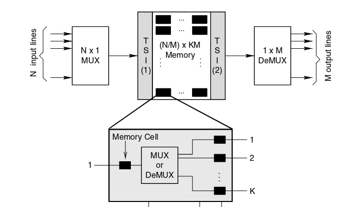
1.5.3.5 Space-Time Division Switch ... 25
1.5.4 IP-Address Lookup: A Bottleneck ... 27
References ... 27
Chapter 2 Concept of IP-Address Lookup and Routing Table ... 31
2.1 IP Address, Prefi x, and Routing Table ... 31
2.2 Concept of IP-Address Lookup ... 32
2.3 Matching Techniques ... 33
2.3.1 Design Criteria and Performance Requirement ... 34
2.4 Diffi culty of the Longest-Prefi x Matching Problem ... 36
2.4.1 Comparisons with ATM Address and Phone Number ... 36
2.4.2 Internet Addressing Architecture ... 36
2.5 Routing Table Characteristics ... 39
2.5.1 Routing Table Structure ... 40
2.5.2 Routing Table Growth ... 41
2.5.3 Impact of Address Allocation on Routing Table ... 43
2.5.3.1 Migration of Address Allocation Policy ... 44
2.5.3.2 Impact of Address Allocations on Routing Table Size ... 45
2.5.3.3 Impact of Address Allocation on Prefi xes with 24-Bit Length ... 46
2.5.4 Contributions to Routing Table Growth ... 46
2.5.4.1 Multi-Homing ... 48
2.5.4.2 Failure to Aggregate ... 48
2.5.4.3 Load Balancing ... 49
2.5.4.4 Address Fragmentation ... 50
2.5.5 Route Update ... 50
2.6 Constructing Optimal Routing Tables ... 52
2.6.1 Filtering Based on Address Allocation Policies ... 52
2.6.1.1 Th ree Filtering Rules ... 52
2.6.1.2 Performance Evaluation ... 54
2.6.2 Minimization of the Routing Table with Address Reassignments ... 55
2.6.2.1 Case of a Single IP Routing Table ... 56
2.6.2.2 General Case ... 59
2.6.3 Optimal Routing Table Constructor ... 63
2.6.3.1 Description of the Algorithm ... 63
2.6.3.2 Improvements ... 66
2.6.3.3 Experiments and Results ... 67
References ... 68
Chapter 3 Classic Schemes ... 69
3.1 Linear Search ... 69
3.2 Caching ... 69
3.2.1 Management Policies ... 70
3.2.1.1 Cache Modeling ... 70
3.2.1.3 Measurement Results ... 72
3.2.1.4 Caching Cost Analysis ... 79
3.2.2 Characteristics of Destination Address Locality ... 80
3.2.2.1 Locality: Concepts ... 80
3.2.2.2 Cache Replacement Algorithms ... 81
3.2.2.3 Stack Reference Frequency ... 83
3.2.2.4 Analysis of Noninteractive Traffi c ... 86
3.2.2.5 Cache Design Issues ... 87
3.2.3 Discussions ... 89
3.3 Binary Trie ... 89
3.4 Path-Compressed Trie ... 91
3.5 Dynamic Prefi x Trie ... 92
3.5.1 Defi nition and Data Structure ... 93
3.5.2 Properties of DP-Tries ... 95
3.5.3 Algorithms for DP-Tries ... 97
3.5.3.1 Insertion ... 97
3.5.3.2 Deletion ... 102
3.5.3.3 Search ... 104
3.5.4 Performance ... 105
References ... 105
Chapter 4 Multibit Tries ... 107
4.1 Level Compression Trie ... 107
4.1.1 Level Compression ... 107
4.1.2 Representation of LC-Tries ... 109
4.1.3 Building LC-Tries ... 111
4.1.4 Experiments ... 112
4.1.5 Modifi ed LC-Tries ... 113
4.2 Controlled Prefi x Expansion ... 113
4.2.1 Prefi x Expansion ... 114
4.2.2 Constructing Multibit Tries ... 115
4.2.3 Effi cient Fixed-Stride Tries ... 116
4.2.4 Variable-Stride Tries ... 118
4.3 Lulea Algorithms ... 123
4.3.1 Level 1 of the Data Structure ... 124
4.3.2 Levels 2 and 3 of the Data Structure ... 127
4.3.3 Growth Limitations in the Current Design ... 128
4.3.4 Performance ... 128
4.4 Elevator Algorithm ... 128
4.4.1 Elevator-Stairs Algorithm ... 129
4.4.2 log W-Elevators Algorithm ... 132
4.4.3 Experiments ... 136
4.5 Block Trees ... 138
4.5.1 Construction of Block Trees ... 138
4.5.2 Lookup ... 140
4.5.3 Updates ... 142
4.5.5 Worst-Case Performance ... 145
4.5.6 Experiments ... 148
4.6 Multibit Tries in Hardware ... 149
4.6.1 Stanford Hardware Trie ... 149
4.6.2 Tree Bitmap ... 150
4.6.3 Tree Bitmap Optimizations ... 154
4.6.4 Hardware Reference Design ... 157
References ... 162
Chapter 5 Pipelined Multibit Tries ... 165
5.1 Fast Incremental Updates for the Pipelined Fixed-Stride Tries ... 165
5.1.1 Pipelined Lookups Using Tries ... 165
5.1.2 Forwarding Engine Model and Assumption ... 167
5.1.3 Routing Table and Route Update Characteristics ... 169
5.1.4 Constructing Pipelined Fixed-Stride Tries ... 170
5.1.5 Reducing Write Bubbles ... 177
5.1.5.1 Separating Out Updates to Short Routes ... 177
5.1.5.2 Node Pullups ... 178
5.1.5.3 Eliminating Excess Writes ... 180
5.1.5.4 Caching Deleted SubTrees ... 181
5.1.6 Summary and Discussion ... 184
5.2 Two-Phase Algorithm ... 185
5.2.1 Problem Statements ... 186
5.2.2 Computing MMS(W− 1, k) ... 186
5.2.3 Computing T(W− 1, k) ... 190
5.2.4 Faster Two-Phase Algorithm for k= 2, 3 ... 192
5.2.5 Partitioning Scheme ... 194
5.2.6 Experimental Results ... 195
5.3 Pipelined Variable-Stride Multibit Tries ... 198
5.3.1 Construction of Optimal PVST ... 199
5.3.2 Mapping onto a Pipeline Architecture ... 200
5.3.3 Experimental Results ... 202
References ... 204
Chapter 6 Effi
cient Data Structures for Bursty Access Patterns ... 205
6.1 Table-Driven Schemes ... 205
6.1.1 Table-Driven Models ... 205
6.1.2 Dynamic Programming Algorithm ... 207
6.1.3 Lagrange Approximation Algorithm ... 209
6.2 Near-Optimal Scheme with Bounded Worst-Case Performance ... 211
6.2.1 Defi nition ... 211
6.2.2 Algorithm MINDPQ ... 213
6.2.3 Depth-Constrained Weight Balanced Tree ... 216
6.2.4 Simulation ... 217
6.3 Dynamic Biased Skip List ... 217
6.3.1 Regular Skip List ... 218
6.3.2.1 Data Structure ... 219
6.3.2.2 Search Algorithm ... 220
6.3.3 Dynamic BSL ... 221
6.3.3.1 Constructing Data Structure ... 221
6.3.3.2 Dynamic Self-Adjustment ... 222
6.3.3.3 Lazy Updating Scheme ... 223
6.3.3.4 Experimental Results ... 224
6.4 Collection of Trees for Bursty Access Patterns ... 225
6.4.1 Prefi x and Range ... 225
6.4.2 Collection of Red-Black Trees (CRBT) ... 226
6.4.3 Biased Skip Lists with Prefi x Trees (BSLPT) ... 227
6.4.4 Collection of Splay Trees ... 229
6.4.5 Experiments ... 230
References ... 234
Chapter 7 Caching Technologies ... 237
7.1 Suez Lookup Algorithm ... 237
7.1.1 Host Address Cache ... 237
7.1.1.1 HAC Architecture ... 237
7.1.1.2 Network Address Routing Table ... 240
7.1.1.3 Simulations ... 242
7.1.2 Host Address Range Cache ... 243
7.1.3 Intelligent HARC ... 244
7.1.3.1 Index Bit Selection ... 244
7.1.3.2 Comparisons between IHARC and HARC ... 246
7.1.3.3 Selective Cache Invalidation ... 248
7.2 Prefi x Caching Schemes ... 248
7.2.1 Liu’s Scheme ... 249
7.2.1.1 Prefi x Cache ... 249
7.2.1.2 Prefi x Memory ... 250
7.2.1.3 Experiments ... 251
7.2.2 Reverse Routing Cache (RRC) ... 252
7.2.2.1 RRC Structure ... 252
7.2.2.2 Handling Parent Prefi xes ... 252
7.2.2.3 Updating RRC ... 253
7.2.2.4 Performance Evaluation ... 255
7.3 Multi-Zone Caches ... 256
7.3.1 Two-Zone Full Address Cache ... 256
7.3.2 Multi-Zone Pipelined Cache ... 257
7.3.2.1 Architecture of MPC ... 257
7.3.2.2 Search in MPC ... 258
7.3.2.3 Outstanding Miss Buff er ... 258
7.3.2.4 Lookup Table Transformation ... 260
7.3.2.5 Performance Evaluation ... 261
7.3.3 Design Method of Multi-Zone Cache ... 261
7.3.3.1 Design Model ... 262
7.3.3.2 Two-Zone Design ... 264
7.4 Cache-Oriented Multistage Structure ... 266
7.4.1 Bi-Directional Multistage Interconnection ... 267
7.4.2 COMS Operations ... 267
7.4.3 Cache Management ... 269
7.4.4 Details of SEs ... 270
7.4.5 Routing Table Partitioning ... 271
References ... 272
Chapter 8 Hashing Schemes ... 275
8.1 Binary Search on Hash Tables ... 275
8.1.1 Linear Search of Hash Tables ... 275
8.1.2 Binary Search of Hash Tables ... 276
8.1.3 Precomputation to Avoid Backtracking ... 277
8.1.4 Refi nements to Basic Scheme ... 278
8.1.4.1 Asymmetric Binary Search ... 278
8.1.4.2 Mutating Binary Search ... 281
8.1.5 Performance Evaluation ... 286
8.2 Parallel Hashing in Prefi x Length ... 287
8.2.1 Parallel Architecture ... 287
8.2.2 Simulation ... 288
8.3 Multiple Hashing Schemes ... 290
8.3.1 Multiple Hash Function ... 290
8.3.2 Multiple Hashing Using Cyclic Redundancy Code ... 292
8.3.3 Data Structure ... 294
8.3.4 Searching Algorithms ... 295
8.3.5 Update and Expansion to IPv6 ... 295
8.3.6 Performance Comparison ... 297
8.4 Using Bloom Filter ... 297
8.4.1 Standard Bloom Filter ... 297
8.4.2 Counting Bloom Filter ... 299
8.4.3 Basic Confi guration of LPM Using Bloom Filter ... 299
8.4.4 Optimization ... 301
8.4.4.1 Asymmetric Bloom Filters ... 302
8.4.4.2 Direct Lookup Array ... 304
8.4.4.3 Reducing the Number of Filters ... 305
8.4.5 Fast Hash Table Using Extended Bloom Filter ... 307
8.4.5.1 Basic Fast Hash Table ... 307
8.4.5.2 Pruned Fast Hash Table ... 309
8.4.5.3 Shared-Node Fast Hash Table ... 312
References ... 314
Chapter 9 TCAM-Based Forwarding Engine ... 317
9.1 Content-Address Memory ... 317
9.1.1 Basic Architectural Elements ... 317
9.1.2 Binary versus Ternary CAMs ... 319
9.2 Effi cient Updating on the Ordered TCAM ... 321
9.2.1 Algorithm for the Prefi x-Length Ordering Constraint ... 321
9.2.2 Algorithm for the Chain-Ancestor Ordering Constraint (CAO_OPT) ... 322
9.2.3 Level-Partitioning Technology ... 322
9.3 VLMP Technique to Eliminate Sorting ... 325
9.3.1 VLMP Forwarding Engine Architecture ... 325
9.3.2 Search Algorithm ... 327
9.3.2.1 First Stage ... 327
9.3.2.2 Second Stage ... 327
9.3.3 Performance of VLMP Architecture ... 327
9.4 Power-Effi cient TCAM ... 328
9.4.1 Pruned Search and Paged-TCAM ... 329
9.4.1.1 Pruned Search ... 329
9.4.1.2 Paged TCAM ... 330
9.4.2 Heuristic Partition Techniques ... 331
9.4.2.1 Bit-Selection Architecture ... 331
9.4.2.2 Trie-Based Table Partitioning ... 334
9.4.2.3 Experiments ... 340
9.4.2.4 Route Updating ... 341
9.4.3 Compaction Techniques ... 343
9.4.3.1 Mask Extension ... 343
9.4.3.2 Prefi x Aggregation and Expansion ... 346
9.4.3.3 EaseCAM: A Two-Level Paged-TCAM Architecture ... 347
9.4.4 Algorithms for Bursty Access Pattern ... 350
9.4.4.1 Static Architecture ... 350
9.4.4.2 Dynamic Architecture ... 352
9.4.4.3 Discussions ... 355
9.5 A Distributed TCAM Architecture ... 356
9.5.1 Analysis of Routing Tables ... 356
9.5.2 Distributed Memory (TCAM) Organization ... 358
9.5.3 LBBTC Algorithm ... 358
9.5.3.1 Mathematical Model ... 359
9.5.3.2 Adjusting Algorithm ... 361
9.5.4 Analysis of the Power Effi ciency ... 362
9.5.5 Complete Implementation Architecture ... 364
9.5.5.1 Index Logic ... 364
9.5.5.2 Priority Selector (Adaptive Load Balancing Logic) ... 365
9.5.5.3 Ordering Logic ... 366
9.5.6 Performance Analysis ... 366
References ... 369
Chapter 10 Routing-Table Partitioning Technologies ... 371
10.1 Prefi x and Interval Partitioning ... 371
10.1.1 Partitioned Binary Search Table ... 371
10.1.1.1 Encoding Prefi xes as Ranges ... 372
10.1.1.3 Insertion into a Modifi ed Binary Search Table ... 375
10.1.1.4 Multiway Binary Search: Exploiting the Cache Line ... 376
10.1.1.5 Performance Measurements ... 378
10.1.2 Multilevel and Interval Partitioning ... 379
10.1.2.1 Multilevel Partitioning ... 380
10.1.2.2 Interval Partitioning ... 383
10.1.2.3 Experimental Results ... 385
10.2 Port-Based Partitioning ... 388
10.2.1 IFPLUT Algorithm ... 388
10.2.1.1 Primary Lookup Table Transformation ... 388
10.2.1.2 Partition Algorithm Based on Next Hops ... 391
10.2.2 IFPLUT Architecture ... 393
10.2.2.1 Basic Architecture ... 393
10.2.2.2 Imbalance Distribution of Prefi xes ... 393
10.2.2.3 Concept of Search Unit ... 394
10.2.2.4 Memory Assignment Scheme ... 395
10.2.2.5 Selector Block ... 395
10.2.2.6 IFPLUT Updates ... 397
10.2.2.7 Implementation Using TCAM ... 398
10.2.2.8 Design Optimization ... 399
10.2.3 Experimental Results ... 400
10.3 ROT-Partitioning ... 401
10.3.1 Concept of ROT-Partitioning ... 401
10.3.2 Generalization of ROT-Partition ... 402
10.3.3 Complexity Analysis ... 404
10.3.4 Results of ROT-Partitioning ... 405
10.3.4.1 Storage Sizes ... 405
10.3.4.2 Worst-Case Lookup Times ... 406
10.4 Comb Extraction Scheme ... 407
10.4.1 Splitting Rule ... 408
10.4.2 Comparison Set ... 412
10.4.3 Implementation Using Binary Trie ... 413
References ... 414
xiii
Preface
Th is book mainly targets high-speed packet networking. As Internet traffi c grows exponentially, there is a great need to build multi-terabit Internet protocol (IP) routers. Th e forwarding engine in routers is the most important part of the high-speed router.
Packet forwarding technologies have been investigated and researched intensively for almost two decades, but there are very few appropriate textbooks describing it. Many engineers and students have to search for technical papers and read them in an ad-hoc manner. Th is book is the fi rst that explains packet forwarding concepts and implementation technologies in broad scope and great depth.
Th is book addresses the data structure, algorithms, and architectures to implement high-speed routers. Th e basic concepts of packet forwarding are described and new technologies are discussed. The book will be a practical guide to aid understanding of IP routers.
We have done our best to accurately describe packet forwarding technologies. If any errors are found, please send an email to [email protected]. We will correct them in future editions.
Audience
Th is book can be used as a reference book for industry people whose job is related to IP networks and router design. It is also intended to help engineers from network equipment and Internet service providers to understand the key concepts of high-speed packet forwarding. Th is book will also serve as a good text for senior and graduate students in electrical engineering, computer engineering, and computer science. Using it, students will understand the technology trend in IP networks so that they can better position themselves when they graduate and look for jobs in the high-speed networking fi eld.
Organization of the Book
Th e book is organized as follows:Chapter 2 explains the background of IP-address lookup by briefl y describing the evolution of the Internet addressing architecture, the characteristics of the routing table, and the complexity of IP-address lookup. It discusses the design criteria and the performance requirements of high-speed routers.
Chapter 3 introduces basic schemes, such as linear search, cache replacement algorithm, binary trie, path-compressed trie, dynamic prefi x trie, and others. We describe the problems of the algorithms proposed before 1996.
Chapter 4 discusses the multibit trie, in which the search operation requires simultaneous inspection of several bits. We describe the principles involved in constructing an effi cient multibit trie and examine some schemes in detail.
Chapter 5 discusses the pipelined ASIC architecture that can produce signifi cant savings in cost, complexity, and space for the high-end router.
Chapter 6 discusses the dynamic data structure of the bursty access pattern. We examine the designs of the data structure and show how to improve the throughput by turning it according to lookup biases.
Chapter 7 introduces the advance caching techniques that speed up packet forwarding. We discuss the impact of traffi c locality, cache size, and the replacement algorithm on the miss ratio.
Chapter 8 discusses the improved hash schemes that can be used for Internet address lookups. We examine the binary search of hash tables, parallel hashing, multiple hashing, and the use of Bloom fi lter.
Chapter 9 discusses the forwarding engine based on TCAM. We examine route update algorithms and power effi cient schemes.
xv
Acknowledgments
Th is book could not have been published without the help of many people. We thank Pankaj Gupta, Srinivasan Vankatachary, Sartaj Sahni, Geoff Huston, Isaac Keslassy, Mikael Degermark, Will Eatherton, Haoyu Song, Marcel Waldvogel, Soraya Kasnavi, Vincent C. Gaudet, H. Jonathan Chao, Vittorio Bilo, Michele Flammini, Ernst W. Biersack, Willibald Doeringer, Gunnar Karlsson, Rama Sangireddy, Mikael Sundstrom, Anindya Basu, Girija Narlikar, Gene Cheung, Funda Ergun, Tzi-cker Chiueh, Mehrdad Nourani, Nian-Feng Tzeng, Hyesook Lim, Andrei Broder, Michael Mitzenmacher, Sarang Dharmapurika, Masayoshi Kobayashi, Samar Sharma, V.C. Ravikumar, Rabi Mahapatra, Kai Zheng, B. Lampson, Haibin Lu, Yiqiang Q. Zhao, and others.
xvii
About the Author
1
Introduction
1.1 Introduction
Th e Internet comprises a mesh of routers interconnected by links, in which routers forward packets to their destinations, and physical links transport packets from one router to another. Because of the scalable and distributed nature of the Internet, there are more and more users connected to it and more and more intensive applications over it. Th e great success of the Internet thus leads to exponential increases in traffi c volumes, stimulating an unprecedented demand for the capacity of the core network. The trend of such exponential growth is not expected to slow down, mainly because data-centric businesses and consumer networking applications continue to drive global demand for broadband access solutions. Th is means that packets have to be transmitted and forwarded at higher and higher rates. To keep pace with Internet traffi c growth, researchers are continually exploring transmission and forwarding technologies.
Advances in fi ber throughput and optical transmission technologies have enabled operators to deploy capacity in a dramatic fashion. For example, dense wavelength division multiplexing (DWDM) equipment can multiplex the signals of 300 channels of 11.6 Gbit/s to achieve a total capacity of more than 3.3 Tbit/s on a single fi ber and transmit them over 7000 km [1]. In the future, DWDM networks will widely support 40 Gbit/s (OC-768) for each channel, and link capacities are keeping pace with the demand for bandwidth.
Historically, network traffi c doubled every year [2], and the speed of optical transmissions (such as DWDM) every seven months [3]. However, the capacity of routers has doubled every 18 months [3], laging behind network traffi c and the increasing speed of optical transmission. Th erefore, the router becomes the bottleneck of the Internet.
1.2 Concept of Routers
Th e Internet can be described as a collection of networks interconnected by routers using a set of communications standards known as the Transmission Control Protocol/Internet Protocol (TCP/IP) suite. TCP/IP is a layered model with logical levels: the application layer, the transport layer, the network layer, and the data link layer. Each layer provides a set of services that can be used by the layer above [4]. The network layer provides the services needed for Internetworking, that is, the transfer of data from one network to another. Routers operate at the network layer, and are sometimes called IP routers.
Routers knit together the constituent networks of the global Internet, creating the illusion of a unifi ed whole. In the Internet, a router generally connects with a set of input links through which a packet can come in and a set of output links through which a packet can be sent out. Each packet contains a destination IP address; the packet has to follow a path through the Internet to its destination. Once a router receives a packet at an input link, it must determine the appropriate output link by looking at the destination address of the packet. The packet is transferred router by router so that it eventually ends up at its destination. Th erefore, the primary functionality of the router is to transfer packets from a set of input links to a set of output links. This is true for most of the packets, but there are also packets received at the router that require special treatment by the router itself.
1.3 Basic Functionalities of Routers
Generally, routers consist of the following basic components: several network interfaces to the attached networks, processing module(s), buff ering module(s), and an internal interconnection unit (or switch fabric). Typically, packets are received at an inbound network interface, processed by the processing module and, possibly, stored in the buff ering module. Th en, they are forwarded through the internal interconnection unit to the outbound interface that transmits them to the next hop on their journey to the fi nal destination. Th e aggregate packet rate of all attached network interfaces needs to be processed, buff ered, and relayed. Th erefore, the processing and memory modules may be replicated either fully or partially on the network interfaces to allow for concurrent operations.
A generic architecture of an IP router is given in Figure 1.1. Figure 1.1a shows the basic archi-tecture of a typical router: the controller card [which holds the central processing unit (CPU)], the router backplane, and interface cards. Th e CPU in the router typically performs such functions as path computations, routing table maintenance, and reachability propagation. It runs whichever routing protocols are needed in the router. Th e interface cards consist of adapters that perform inbound and outbound packet forwarding (and may even cache routing table entries or have exten-sive packet processing capabilities). Th e router backplane is responsible for transferring packets between the cards. Th e basic functionalities in an IP router can be categorized as: route processing, packet forwarding, and router special services. Th e two key functionalities are route processing (i.e., path computation, routing table maintenance, and reachability propagation) and packet forward-ing, shown in Figure 1.1b. We discuss the three functionalities in more detail subsequently.
1.3.1 Route
Processing
such as the Routing Information Protocol (RIP) and Open Shortest Path First (OSPF) [5–7]. Th e routing table consists of routing entries that specify the destination and the next-hop router through which the packets should be forwarded to reach the destination. Route calculation consists of determining a route to the destination: network, subnet, network prefi x, or host.
In static routing, the routing table entries are created by default when an interface is confi g-ured (for directly connected interfaces), added by, for example, the route command (normally from a system bootstrap fi le), or created by an Internet Control Message Protocol (ICMP) redirect (usually when the wrong default is used) [8]. Once confi gured, the network paths will not change. With static routing, a router may issue an alarm when it recognizes that a link has gone down, but will not automatically reconfi gure the routing table to reroute the traffi c around the disabled link. Static routing, used in LANs over limited distances, requires basically the network manager to confi gure the routing table. Th us, static routing is fi ne if the network is small, there is a single connection point to other networks, and there are no redundant routes (where a backup route can be used if a primary route fails). Dynamic routing is normally used if any of these three conditions do not hold true.
Dynamic routing, used in Internetworking across wide area networks, automatically reconfi gures the routing table and recalculates the least expensive path. In this case, routers broadcast advertise-ment packets (signifying their presence) to all network nodes and communicate with other routers about their network connections, the cost of connections, and their load levels. Convergence, or reconfi guration of the routing tables, must occur quickly, before routers with incorrect information misroute data packets into dead ends. Some dynamic routers can also rebalance the traffi c load.
Th e use of dynamic routing does not change the way an IP forwarding engine performs routing at the IP layer. What changes is the information placed in the routing table—instead of coming from the route commands in bootstrap fi les, the routes are added and deleted dynamically by a routing protocol, as routes change over time. Th e routing protocol adds a routing policy to the system, choosing which routes to place in the routing table. If the protocol fi nds multiple routes to a destination, the protocol chooses which route is the best, and which one to insert in the table. Figure 1.1 Generic architecture of a router. (From Aweya, J., Journal of Systems Architecture, 46, 6, 2000. With permission.)
If the protocol fi nds that a link has gone down, it can delete the aff ected routes or add alternate routes that bypass the problem.
A network (including several networks administered as a whole) can be defi ned as an autono-mous system. A network owned by a corporation, an Internet Service Provider (ISP), or a university campus often defi nes an autonomous system. Th ere are two principal routing protocol types: those that operate within an autonomous system, or the Interior Gateway Protocols (IGPs), and those that operate between autonomous systems, or Exterior Gateway Protocols (EGPs). Within an autono-mous system, any protocol may be used for route discovery, propagating, and validating routes. Each autonomous system can be independently administered and must make routing information available to other autonomous systems. Th e major IGPs include RIP, OSPF, and Intermediate System to Intermediate System (IS–IS). Some EGPs include EGP and Border Gateway Protocol (BGP).
1.3.2 Packet
Forwarding
In this section, we briefl y review the forwarding process in IPv4 routers. More details of the for-warding requirements are given in Ref. [9]. A router receives an IP packet on one of its interfaces and then forwards the packet out of another of its interfaces (or possibly more than one, if the packet is a multicast packet), based on the contents of the IP header. As the packet is forwarded hop by hop, the packet’s (original) network layer header (IP header) remains relatively unchanged, containing the complete set of instructions on how to forward the packet (IP tunneling may call for prepending the packet with other IP headers in the network). However, the data-link headers and physical-transmission schemes may change radically at each hop to match the changing media types.
Suppose that the router receives a packet from one of its attached network segments, the router verifi es the contents of the IP header by checking the protocol version, header length, packet length, and header checksum fi elds. Th e protocol version must be equal to 4 for IPv4, for which the header length must be greater than or equal to the minimum IP header size (20 bytes). Th e length of the IP packet, expressed in bytes, must also be larger than the minimum header size. In addition, the router checks that the entire packet has been received by checking the IP packet length against the size of the received Ethernet packet, for example, in the case where the interface is attached to an Ethernet network. To verify that none of the fi elds of the header have been cor-rupted, the 16-bit ones-complement checksum of the entire IP header is calculated and verifi ed to be equal to 0×ff ff . If any of these basic checks fail, the packet is deemed to be malformed and is dis-carded without sending an error indication back to the packet’s originator.
Next, the router verifi es that the time-to-live (TTL) fi eld is greater than 1. Th e purpose of the TTL fi eld is to make sure that packets do not circulate forever when there are routing loops. Th e host sets the packet’s TTL fi eld to be greater than or equal to the maximum number of router hops expected on the way to the destination. Each router decrements the TTL fi eld by 1 when forward-ing; when the TTL fi eld is decremented to 0, the packet is discarded, and an ICMP TTL exceeded message is sent back to the host. On decrementing the TTL, the router must update the packet’s header checksum. RFC1624 [10] contains implementation techniques for computing the IP checksum. Because a router often changes only the TTL fi eld (decrementing it by 1), it can incre-mentally update the checksum when it forwards a received packet, instead of calculating the checksum over the entire IP header again.
(broadcast). Unicast packets are discarded if they were received as data-link broadcasts or as mul-ticasts; otherwise, multiple routers may attempt to forward the packet, possibly contributing to a broadcast storm. In packet forwarding, the destination IP address is used as a key for the routing table lookup. Th e best-matching routing table entry is returned, indicating whether to forward the packet and, if so, the interface to forward the packet out of and the IP address of the next IP router (if any) in the packet’s path. Th e next-hop IP address is used at the output interface to determine the link address of the packet, in case the link is shared by multiple parties [such as an Ethernet, Token Ring, or Fiber Distributed Data Interface (FDDI) network], and is consequently not needed if the output connects to a point-to-point link.
In addition to making forwarding decisions, the forwarding process is responsible for making packet classifi cations for quality of service (QoS) control and access fi ltering. Flows can be identi-fi ed based on source IP address, destination IP address, TCP/UDP port numbers as well as IP type of service (TOS) fi eld. Classifi cation can even be based on higher layer packet attributes.
If the packet is too large to be sent out of the outgoing interface in one piece [i.e., the packet length is greater than the outgoing interface’s Maximum Transmission Unit (MTU)], the router attempts to split the packet into smaller fragments. Fragmentation, however, can aff ect performance adversely [11]. Th e host may instead wish to prevent fragmentation by setting the Don’t Fragment (DF) bit in the fragmentation fi eld. In this case, the router does not fragment the packet, but instead drops it and sends an ICMP Destination Unreachable (subtype fragmentation needed and DF set) message back to the host. Th e host uses this message to calculate the minimum MTU along the packet’s path [12], which in turn is used to size future packets.
Th e router then prepends the appropriate data-link header for the outgoing interface. Th e IP address of the next hop is converted to a data-link address, usually using the Address Resolution Protocol (ARP) [13] or a variant of ARP, such as Inverse ARP [14] for Frame Relay subnets. Th e router then sends the packet to the next hop, where the process is repeated.
An application can also modify the handling of its packets by extending the IP headers of its packets with one or more IP options. IP options are used infrequently for regular data packets, because most Internet routers are heavily optimized for forwarding packets having no options. Most IP options (such as the record-route and timestamp options) are used to aid in statistics col-lection, but do not aff ect a packet’s path. However, the strict-source route and the loose-source route options can be used by an application to control the path its packets take. Th e strict-source route option is used to specify the exact path that the packet will take, router by router. Th e utility of a strict-source route is limited by the maximum size of the IP header (60 bytes), which limits to 9 the number of hops specifi ed by the strict-source route option. Th e loose-source route is used to specify a set of intermediate routers (again, up to 9) through which the packet must go on the way to its destination. Loose-source routing is used mainly for diagnostic purposes, for instance, as an aid to debugging Internet routing problems.
1.3.3 Router Special Services
whose matching packets should not be forwarded or of more complex rules to deal with protocols that vary their port numbers over time, such as the File Transfer Protocol (FTP). Such routers are called fi rewalls. Similarly, ISPs often confi gure their routers to verify the source address in all packets received from the ISP’s customers. Th is foils certain security attacks and makes other attacks easier to trace back to their source. Similarly, ISPs providing dial-in access to their routers typically use Remote Authentication Dial-In User Service (RADIUS) [15] to verify the identity of the person dialing in.
Often, other functions less directly related to packet forwarding also get incorporated into IP routers. Examples of these nonforwarding functions include network management components, such as Simple Network Management Protocol (SNMP) and Management Information Bases (MIBs). Routers also play an important role in TCP/IP congestion control algorithms. When an IP network is congested, routers cannot forward all the packets they receive. By simply discarding some of their received packets, routers provide feedback to TCP congestion control algorithms, such as the TCP slow-start algorithm [16,17]. Early Internet routers simply discarded excess pack-ets instead of queuing them onto already full transmit queues; these routers are termed drop-tail gateways. However, this discard behavior was found to be unfair, favoring applications that send larger and more bursty data streams. Modern Internet routers employ more sophisticated, and fairer, drop algorithms, such as Random Early Detection (RED) [18].
Algorithms also have been developed that allow routers to organize their transmit queues so as to give resource guarantees to certain classes of traffi c or to specifi c applications. Th ese queuing or link scheduling algorithms include Weighted Fair Queuing (WFQ) [19] and Class Based Queuing (CBQ) [20]. A protocol called Resource Reservation Protocol (RSVP) [21] has been developed that allows hosts to dynamically signal to routers which applications should get special queuing treatment. However, RSVP has not yet been deployed, with some people arguing that queuing preference could more simply be indicated by using the TOS bits in the IP header [22,23].
Some vendors allow collection of traffi c statistics on their routers: for example, how many pack-ets and bytes are forwarded per receiving and transmitting interface on the router. Th ese statistics are used for future capacity planning. Th ey can also be used by ISPs to implement usage-based charging schemes for their customers.
Th erefore, IP routers’ functions can be classifi ed into two types: datapath functions and control functions. Datapath functions are performed on every packet that passes through the router. Th ese include forwarding decisions, switching through the backplane, and output link scheduling. These are most often implemented in special purpose hardware, called a forwarding engine.
Control functions include system confi guration, management, and exchange of routing table information with neighboring routers. Th ese are performed relatively infrequently. Th e route controller exchanges topology information with other routers and constructs a routing table based on a routing protocol (e.g., RIP, OSPF, and BGP). It can also create a forwarding table for the forwarding engine. Control functions are not processed for each arriving packet, because speed is not critical, they are implemented in software.
1.4 Evolution of Router Architecture
Routers are the core equipment in the Internet, and are found at every level in the Internet. Routers in access networks allow homes and small businesses to connect to an ISP. Routers in enterprise networks link tens of thousands of computers within a campus or enterprise. Routers in the back-bone link together ISPs and enterprise networks with long distance trunks.
Th e rapid growth of the Internet has created diff erent challenges for routers in backbone, enterprise, and access networks. Th e backbone needs routers capable of routing at high speeds on a few links. Enterprise routers should have a low cost per port, a large number of ports, be easy to confi gure, and support QoS. Finally, access routers should support many heterogeneous, high-speed ports, a variety of protocols at each port, and so on. All of these challenges drive the improvement of the routers in datapath functions and control functions.
Th e Internet has been in operation since the 1970s, and routers have gone through several design generations over the decades. Th e evolution of routers is often described in terms of three generations of architecture by Aweya [27] until 1999. Nick McKeown proposes the fourth generation and the future of router architecture [28,29].
1.4.1
First Generation—Bus-Based Router Architectures
with Single Processor
Th e earliest routers (until the mid-to-late 1980s) were based on software implementations on a CPU. These routers consist of a general-purpose processor and multiple interface cards interconnected through a shared bus, as depicted in Figure 1.2.
Packets arriving at the interfaces are forwarded to the CPU, which determines the next-hop address and sends them back to the appropriate outgoing interface(s). Data are usually buff ered in a centralized data memory, which leads to the disadvantage of having the data cross the bus twice, making it the major system bottleneck. Packet processing and node management software (including routing protocol operations, routing table maintenance, routing table lookups, and other control and management protocols such as ICMP and SNMP) are also implemented on
Line Card
DMA
MAC
Line Card
DMA
MAC
Line Card
DMA
MAC
Route Processor
(CPU)
Memory
Bus
the central processor. Unfortunately, this simple architecture yields low performance for the following reasons:
Th e central processor has to process all packets fl owing through the router (as well as those destined to it). Th is represents a serious processing bottleneck.
Some major packet processing tasks in a router involve memory-intensive operations (e.g., table lookups), which limits the eff ectiveness of processor power upgrades in boosting the router packet processing throughput. Routing table lookups and data movements are the major consumers of overall packet processing cycles. Packet processing time does not decrease linearly if faster processors are used because of the sometimes dominating eff ect of the memory access rate.
Moving data from one interface to the other (either through main memory or not) is a time consuming operation that often exceeds the packet header processing time. In many cases, the computer input/output (I/O) bus quickly becomes a severe limiting factor to overall router throughput.
Because routing table lookup is a time-consuming process of packet forwarding, some traditional software-based routers cache the IP destination-to-next-hop association in a separate database that is consulted as the front end to the routing table before the routing table lookup. Th e justification for route caching is that packet arrivals are temporally correlated, so that if a packet belonging to a new fl ow arrives, then more packets belonging to the same fl ow can be expected to arrive in the near future. Route caching of IP destination/next-hop address pairs will decrease the average processing time per packet if locality exists for packet addresses [30]. Still, the performance of the traditional bus-based router depends heavily on the throughput of the shared bus and on the forwarding speed of the central processor. Th is architecture cannot scale to meet the increasing throughput requirements of multigigabit network interface cards.
1.4.2
Second Generation—Bus-Based Router Architectures
with Multiple Processors
For the second generation IP routers, improvement in the shared-bus router architecture was introduced by distributing the packet forwarding operations. In some architectures, distributing fast processors and route caches, in addition to receive and transmit buff ers, over the network interface cards reduces the load on the system bus. Other second generation routers remedy this problem by employing multiple forwarding engines (dedicated solely to packet forwarding opera-tion) in parallel because a single CPU cannot keep up with requests from high-speed input ports. An advantage of having multiple forwarding engines serving as one pool is the ease of balancing loads from the ports when they have diff erent speeds and utilization levels. We review, in this section, these second generation router architectures.
1.4.2.1 Architectures with Route Caching
Th is architecture reduces the number of bus copies and speeds up packet forwarding by using a route cache of frequently seen addresses in the network interface, as shown in Figure 1.3. Packets are therefore transmitted only once over the shared bus. Th us, this architecture allows the network interface cards to process packets locally some of the time.
䡲
䡲
In this architecture, a router keeps a central master routing table and the satellite processors in the network interfaces each keep only a modest cache of recently used routes. If a route is not in a network interface processor’s cache, it would request the relevant route from the central table. Th e route cache entries are traffi c-driven in that the fi rst packet to a new destination is routed by the main CPU (or route processor) via the central routing table information and as part of that forward-ing operation, a route cache entry for that destination is then added in the network interface. Th is allows subsequent packet fl ows to the same destination network to be switched based on an effi cient route cache match. Th ese entries are periodically aged out to keep the route cache current and can be immediately invalidated if the network topology changes. At high speeds, the central routing table can easily become a bottleneck, because the cost of retrieving a route from the central table is many times more expensive than actually processing the packet local in the network interface.
A major limitation of this architecture is that it has a traffi c-dependent throughput and also the shared bus is still a bottleneck. Th e performance of this architecture can be improved by enhancing each of the distributed network interface cards with larger memories and complete for-warding tables. Th e decreasing cost of high-bandwidth memories makes this possible. However, the shared bus and the general purpose CPU can neither scale to high-capacity links nor provide traffi c pattern-independent throughput.
1.4.2.2 Architectures with Multiple Parallel Forwarding Engines
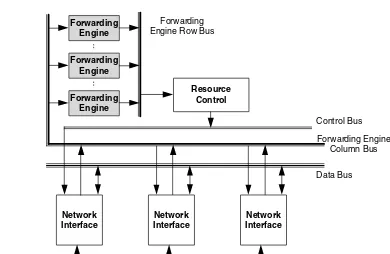
Another bus-based multiple processor router architecture is described in Ref. [31]. Multiple forwarding engines are connected in parallel to achieve high-packet processing rates as shown in Figure 1.4. Th e network interface modules transmit and receive data from links at the required rates. As a packet comes into a network interface, the IP header is stripped by a control circuitry, augmented with an identifying tag, and sent to a forwarding engine for validation and routing. Figure 1.3 Reducing the number of bus copies using a route cache in the network interface. (From Aweya, J., Journal of Systems Architecture, 46, 6, 2000. With permission.)
DMA
MAC
Route Cache
Memory
Route Processor
(CPU)
Memory
Bus
Cache Updates
Line Card Line
Card
Line Card
DMA
MAC
Route Cache
Memory
DMA
MAC
Route Cache
While the forwarding engine is performing the routing function, the remainder of the packet is deposited in an input buff er (in the network interface) in parallel. The forwarding engine determines which outgoing link the packet should be transmitted on, and sends the updated header fi elds to the appropriate destination interface module along with the tag information. Th e packet is then moved from the buff er in the source interface module to a buff er in the destination interface module and eventually transmitted on the outgoing link.
Th e forwarding engines can each work on diff erent headers in parallel. Th e circuitry in the interface modules peels the header off from each packet and assigns the headers to the forwarding engines in a round-robin fashion. Because in some (real time) applications packet order maintenance is an issue, the output control circuitry also goes round-robin, guaranteeing that packets will then be sent out in the same order as they were received. Better load-balancing may be achieved by hav-ing a more intelligent input interface, which assigns each header to the lightest loaded forwardhav-ing engine [31]. Th e output control circuitry would then have to select the next forwarding engine to obtain a processed header from by following the demultiplexing order followed at the input, so that order preservation of packets is ensured. Th e forwarding engine returns a new header (or multiple headers, if the packet is to be fragmented), along with routing information (i.e., the immediate destination of the packet). A route processor runs the routing protocols and creates a forwarding table that is used by the forwarding engines.
Th e choice of this architecture was premised on the observation that it is highly unlikely that all interfaces will be bottlenecked at the same time. Hence sharing of the forwarding engines can increase the port density of the router. Th e forwarding engines are only responsible for resolving next-hop addresses. Forwarding only IP headers to the forwarding engines eliminates an unneces-sary packet payload transfer over the bus. Packet payloads are always directly transferred between Figure 1.4 Bus-based router architecture with multiple parallel forwarding engines. (From Aweya, J., Journal of Systems Architecture, 46, 6, 2000. With permission.)
Network Interface
Forwarding Engine
Forwarding Engine
Resource Control
Forwarding Engine Row Bus
Network Interface
Network Interface
Forwarding Engine Column Bus
Data Bus Control Bus
the interface modules and they never go to either the forwarding engines or the route processor unless they are specifi cally destined to them.
1.4.3 Third Generation—Switch Fabric-Based Router Architecture
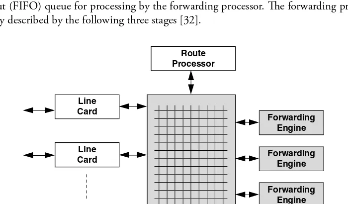
To alleviate the bottlenecks of the second generation of IP routers, the third generation of routers was designed with the shared bus replaced by a switch fabric. Th is provides suffi cient bandwidth for transmitting packets between interface cards and allows throughput to be increased by several orders of magnitude. With the interconnection unit between interface cards not the bottleneck, the new bottleneck is packet processing.Th e multigigabit router (MGR) is an example of this architecture [32]. Th e design has dedi-cated IP packet forwarding engines with route caches in them. Th e MGR consists of multiple linecards (each supporting one or more network interfaces) and forwarding engine cards, all connected to a high-speed (crossbar) switch as shown in Figure 1.5.
Th e design places forwarding engines on boards distinct from linecards. When a packet arrives at a linecard, its header is removed and passed through the switch to a forwarding engine. Th e remainder of the packet remains on the inbound linecard. Th e forwarding engine reads the header to determine how to forward the packet and then updates the header and sends the updated header and its forwarding instructions back to the inbound linecard. Th e inbound linecard integrates the new header with the rest of the packet and sends the entire packet to the outbound linecard for transmission. Th e MGR, like most routers, also has a control (and route) processor that provides basic management functions, such as generation of routing tables for the forwarding engines and link (up/down) management. Each forwarding engine has a set of the forwarding tables (which are a summary of the routing table data).
In the MGR, once headers reach the forwarding engine, they are placed in a request fi rst-in-fi rst-out (FIFO) queue for processing by the forwarding processor. Th e forwarding process can be roughly described by the following three stages [32].
Route Processor
Line Card
Forwarding Engine
Switch Fabric Line
Card
Line Card
Forwarding Engine
Forwarding Engine
Th e fi rst stage includes the following that are done in parallel:
Th e forwarding engine does basic error checking to confi rm that the header is indeed from an IPv4 datagram;
It confi rms that the packet and header lengths are reasonable; It confi rms that the IPv4 header has no options.
In the second stage, the forwarding engine checks to see if the cached route matches the desti-nation of the datagram (a cache hit). If not, the forwarding engine carries out an extended lookup of the forwarding table associated with it. In this case, the processor searches the routing table for the correct route, and generates a version of the route for the route cache. Because the forwarding table contains prefi x routes and the route cache is a cache of routes for a particular destination, the processor has to convert the forwarding table entry into an appropriate destination-specifi c cache entry. Th en, the forwarding engine checks the IP TTL fi eld and computes the updated TTL and IP checksum, and determines if the packet is for the router itself.
In the third stage, the updated TTL and checksum are put in the IP header. Th e necessary routing information is extracted from the forwarding table entry and the updated IP header is written out along with link-layer information from the forwarding table.
1.4.4 Fourth Generation—Scaling Router Architecture Using Optics
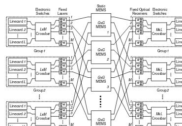
Th ree generations of routers built around a single-stage crossbar and a centralized scheduler do not scale, and (in practice) do not provide the throughput guarantees that network operators need to make effi cient use of their expensive long-haul links. Keslassy et al. propose a scaling router architecture using optics, shown in Figure 1.6 [33].Th e router combines the massive information densities of optical communications, and the fast and fl exible switching of the electronics. It has multiple racks that are connected by optical fi bers, each rack has a group of linecards. In Figure 1.6, the architecture is arranged as G groups of L linecards. In the center, M statically confi gured G × G Micro-Electro-Mechanical Systems (MEMS) switches [34] interconnect the G groups. The MEMS switches are reconfi gured only when a linecard is added or removed and provide the ability to create the needed paths to distribute the data to the linecards that are actually present. Each group of linecard spreads packets over the MEMS switches using an L × M electronic crossbar. Each output of the electronic crossbar is connected to a diff erent MEMS switch over a dedicated fi ber at a fi xed wavelength (the lasers are not tunable). Packets from the MEMS switches are spread across the L linecards in a group by an M × L electronic crossbar. The architecture has the following advantages [33]:
1. Multirack routers spread the system power over multiple racks, reducing power density. 2. Th e switch fabric consists of three stages. It is the extension of the load-balanced router
architecture [35] and has provably 100 percent throughput without a central scheduler. 3. All linecards are partitioned into G groups. The groups are connected together by M diff erent
G × G middle stage switches. The architecture can handle a very large number of linecards. 4. Th e high-capacity MEMS switches change only when linecards are added or moved. Only the
lower-capacity local switches (crossbar) in each group need to be reconfi gured frequently.
To design a 100 Tb/s router that implements the requirements of RFC 1812 [24], Keslassy et al. used the scalable router architecture. The router is assumed to occupy G = 40 multiple racks,
䡲
as shown in Figure 1.7, with up to L= 16 linecards per rack. Each linecard operates at 160 Gb/s. Its input block performs address lookup, segments the variable length packet into one or more fi xed length packets, and then forwards the packet to the local crossbar switch. Its output block receives packets from the local crossbar switch, collects them together, reassembles them into Figure 1.6 A hybrid optical-electrical router architecture. (From Isaac Keslassy, I. et al., Proceedings of ACM SIGCOMM, Karlsruhe, Germany, 2003, New York, ACM Press, 2003. With permission.)
Figure 1.7 A 100Tb/s router example. (From Isaac Keslassy, I. et al., Proceedings of ACM SIGCOMM, Karlsruhe, Germany, 2003, New York, ACM Press, 2003. With permission.)
variable length packets and delivers them to the external line. Forty racks and 55 (= L +G ) statically confi gured 40 × 40 MEMS switches are connected by optical fi bers. In terms of optical technology, it is possible to multiplex and demultiplex 64 Wavelength-Division-Multiplexing channels onto a single optical fi ber, and that each channel can operate at up to 10 Gb/s.
In future, as optical technology matures, it will be possible to replace the hybrid optical– electrical switch with an all-optical fabric. This has the potential to reduce power further by eliminating many electronic crossbars and serial links.
1.5 Key Components of a Router
From the fi rst to the fourth generation, all routers must process headers of packets, switch packet-by-packet, and buff er packets during times of congestion. Therefore, the key components of a router are the forwarding engine to lookup IP address, the switch fabric to exchange packets between linecards, and the scheduler to manage the buff er.
As the router architectures change from centralized mode to distributed mode, more and more functions, such as buff er, IP-address lookup, and traffi c management, are moved to linecards. Linecards become more complex and consume more power. To reduce power density, high-capacity routers use a multirack system with distributed, multistage switch fabrics. So, linecards and switch fabrics are the key components that implement the datapath functions. We will next discuss the line-card, network processor and switch fabric. Subsections 1.5.1 and 1.5.2 are from [36] (© 2002 IEEE).
1.5.1 Linecard
Th e linecards are the entry and exit points of data to and from a router. Th ey provide the interface from the physical and higher layers to the switch fabric. Th e tasks provided by linecards are becoming more complex as new applications develop and protocols evolve.
Each linecard supports at least one full-duplex fi ber connection on the network side, and at least one ingress and one egress connection to the switch fabric backplane. Generally speaking, for high-bandwidth applications, such as OC-48 (2.5 Gb/s) and above, the network connections support channelization for aggregation of lower-speed lines into a large pipe, and the switch fabric connections provide fl ow-control mechanisms for several thousand input and output queues to regulate the ingress and egress traffi c to and from the switch fabric.
A linecard usually includes components such as a transponder, framer, network processor (NP), traffi c manager (TM), and CPU, shown in Figure 1.8 [36].
1.5.1.1 Transponder/Transceiver
Th is component performs optical-to-electrical and electrical-to-optical signal conversions and serial-to-parallel and parallel-to-serial conversions.
1.5.1.2 Framer
It generates section, line, and path bit interleaved parity (B1/B2/B3) for far-end performance monitoring. On the receiver side, it processes the section, line, and path overhead. It performs frame delineation, descrambling, alarm detection, pointer interpretation, bit interleaved parity monitoring (B1/B2/B3), and error count accumulation for performance monitoring [37].
1.5.1.3 Network Processor (NP)
Th e NP mainly performs IP-address lookup, packet classifi cation, and packet modifi cation. It can perform at the line rate using external memory, such as static RAMs (SRAMs), DRAM, or content addressable memory (CAMs). Th e NPs are considered as fundamental a part of routers and other network equipment as a microprocessor is for personal computers. Various architectures for the NP are discussed in the next section.
1.5.1.4 Traffi c Manager
To meet each connection and service class requirement, the traffi c manager (TM) performs various control functions on packet streams, including traffi c access control, buff er management, and packet scheduling. Traffi c access control consists of a collection of specifi cation techniques and mechanisms to: (i) specify the expected traffi c characteristics and service requirements (e.g., peak rate, required delay bound, and loss tolerance) of a data stream; (ii) shape (i.e., delay) data streams (e.g., reducing their rates or burstiness); and (iii) police data streams and take corrective actions (e.g., discard, delay, or mark packets) when traffi c deviates from its specifi cation. Th e usage parameter control (UPC) in the asynchronous transfer mode (ATM) and the diff erentiated service (Diff Serv) in the IP perform similar access control functions at the network edge. Buff er management performs Figure 1.8 A typical router architecture. (From Chao, H., Proceedings of the IEEE, 90. With permission.)
Switch Fabric Transponder/
Transceiver Framer
Network Processor
Memory
CPU Memory
Traffic Manager
Router Controller
Management Controller
Line Card 1
Transponder/
Transceiver Framer
Network Processor
Memory
CPU Memory
packet discarding, according to loss requirements and priority levels, when the buff er exceeds a cer-tain threshold. Th e proposed schemes include random early packet discard (RED), weighted RED, early packet discard (EPD), and partial packet discard (PPD). Packet scheduling ensures that pack-ets are transmitted to meet each connection’s allocated bandwidth/delay requirements. Th e proposed schemes include defi cit round-robin, WFQ and its variants, such as shaped virtual clock [38] and worst-case fairness WFQ (WF2Q+) [39]. Th e last two algorithms achieve the worst-case fairness properties. Many QoS control techniques, algorithms, and implementation architectures can be found in Ref. [40]. The TM may also manage many queues to resolve contention among the inputs of a switch fabric, for example, hundreds or thousands of virtual output queues (VOQs).
1.5.1.5 CPU
Th e CPU performs control plane functions including connection setup/tear-down, forwarding table updates, register/buff er management, and exception handling. Th e CPU is usually not in-line with the fast-path on which the maximum-bandwidth network traffi c moves between the interfaces and the switch fabric.
1.5.2 Network Processor (NP)
It is widely believed that the NP is the most eff ective solution to the challenges facing the commu-nication industry regarding its ability to meet the time-to-market need with products at increas-ingly higher speed, while supporting the convergence and globalization trends of IP traffi c. However, diff erent router features and switch fabric specifi cations require a suitable NP with a high degree of fl exibility to handle a wide variety of functions and algorithms. For instance, it is desirable for an NP to be universally applicable across a wide range of interfaces, protocols, and product types. Th is requires programmability at all levels of the protocol stack, from layer 2 through layer 7. However, this fl exibility is a tradeoff with performance, such as speed and capacity.
Currently, a wide variety of the NPs on the market off er diff erent functions and features. Th e way to select the proper NP depends on the applications, features, fl exibility in protocols and algorithms, and scalability in the number of routes and fl ows. In general, NPs are classifi ed by the achievable port speed, function list capability and programmability, hardware assisting functions, for example, hashing, tree structure, fi ltering, classifi er for security, check sum or cyclic redundancy check (CRC) data, and operation speed (i.e., clock frequency of embedded processors).
With current router requirements, a single-processor system may not be able to meet router processing demands due to the growing gap between the link and processor speeds. With increas-ing port speeds, packets arrive faster than a sincreas-ingle processor can process them. However, because packet streams have dependencies only among packets of the same fl ow and not across diff erent fl ows, the processing of these packets can be easily distributed over several processors working in parallel. Th e current state of integrated circuit technology enables multiple processors to be built on a single silicon die. To support high performance, fl exibility, and scalability, the NP architec-ture must eff ectively address effi cient handling of I/O events (memory access and interrupts), scheduling process management, and provide a diff erent set of instructions to each processor.
to a shared memory and I/O through a switch fabric. When packets of the same fl ow are processed in diff erent processors, interprocessor communication is required. Th is causes memory dependen-cies and may limit the fl exibility of partitioning the function across multiple processors.
Very long instruction word (VLIW) processing has a structure similar to MIMD processing, except that it uses multiple special-purpose coprocessors that can simultaneously perform diff erent tasks. Th ey are specifi cally designed for certain functions and thus can achieve high-data rates. Because these coprocessors are function-specifi c, adaptation of new functions and protocols is restricted.
According to the implementation style and the type of embedded processor, NPs can be classifi ed into the following two broad groups:
Confi gurable. Th is kind of NP consists of multiple special-purpose coprocessors intercon-nected by a confi gurable network, and a manager handling the interconnect confi guration, the memory access, and the set of instructions used by the coprocessors. Figure 1.9 shows an example of a confi gurable NP.
A coprocessor can perform a predefi ned set of functions (e.g., longest or exact prefi x match instructions for table lookup or classifi cation). Th e manager instructs the coprocessors what functions can be performed from the available set and selects a path along which packets fl ow among the coprocessors. When a packet arrives at the NP, the manager routes the packet to a classifi -cation and table lookup coprocessor. After the packet is processed by the coprocessor, it is passed to the next one (the packet analysis and modifi cation unit) in the pipeline. After the packet has been modifi ed, it is passed to the next coprocessor (switch fabric forwarding), where it may be segmented into cells and wait to be transmitted to the switch fabric (assuming no TM follows the NP). When the packet processing is completed, the manager schedules the time the packet exits the NP.
Th is NP is designed with a narrow set of function choices to optimize the chip area and speed. Th e advantage of this NP is that the embedded coprocessors can be designed for high performance.
䡲
Input
Special purpose coprocessor
Manager Classification
and table lookup
Classification and table lookup
Classification and table lookup
Classification and table lookup
Classification and table lookup
Classification and table lookup
Classification and table lookup
Classification and table lookup
Classification and table lookup
Output