Broadband Packet Switching Technologies: A Practical Guide to ATM Switches and IP Routers H. Jonathan Chao, Cheuk H. Lam, Eiji Oki Copyright䊚2001 John Wiley & Sons, Inc.
Ž . Ž .
ISBNs: 0-471-00454-5 Hardback ; 0-471-22440-5 Electronic
BROADBAND PACKET
BROADBAND PACKET
SWITCHING TECHNOLOGIES
A Practical Guide to ATM Switches
and IP Routers
H. JONATHAN CHAO
CHEUK H. LAM
EIJI OKI
A Wiley-Interscience Publication JOHN WILEY & SONS, INC.
Designations used by companies to distinguish their products are often claimed as trademarks. In all instances where John Wiley & Sons, Inc., is aware of a claim, the product names appear in initial capital or ALL CAPITAL LETTERS. Readers, however, should contact the appropriate companies for more complete information regarding trademarks and registration.
Copyright䊚2001 by John Wiley & Sons, Inc. All rights reserved.
No part of this publication may be reproduced, stored in a retrieval system or transmitted in any form or by any means, electronic or mechanical, including uploading, downloading, printing, decompiling, recording or otherwise, except as permitted under Sections 107 or 108 of the 1976 United States Copyright Act, without the prior written permission of the Publisher. Requests to the Publisher for permission should be addressed to the Permissions Department, John Wiley & Sons, Inc., 605 Third Avenue, New York, NY
Ž . Ž .
10158-0012, 212 850-6011, fax 212 850-6008, E-Mail: PERMREQ & WILEY.COM.
This publication is designed to provide accurate and authoritative information in regard to the subject matter covered. It is sold with the understanding that the publisher is not engaged in rendering professional services. If professional advice or other expert assistance is required, the services of a competent professional person should be sought.
ISBN 0-471-22440-5
This title is also available in print as ISBN 0-471-00454-5
PREFACE xiii
1 INTRODUCTION 1
1.1 ATM Switch Systems r 3
1.1.1 Basics of ATM networks r 3 1.1.2 ATM switch structure r 5 1.2 IP Router Systems r 8
1.2.1 Functions of IP routers r 8 1.2.2 Architectures of IP routers r 9
1.3 Design Criteria and Performance Requirements r 13 References r 14
2 BASICS OF PACKET SWITCHING 15
2.1 Switching Concepts r 17
2.1.1 Internal link blocking r 17 2.1.2 Output port contention r 18 2.1.3 Head-of-line blocking r 19 2.1.4 Multicasting r 19
2.1.5 Call splitting r 20
2.2 Switch Architecture Classification r 21 2.2.1 Time division switching r 22
CONTENTS
vi
2.2.2 Space division switching r 24 2.2.3 Buffering strategies r 34 2.3 Performance of Basic Switches r 37
2.3.1 Input-buffered switches r 37 2.3.2 Output-buffered switches r 40
2.3.3 Completely shared-buffer switches r 44 References r 46
3 INPUT-BUFFERED SWITCHES 49
3.1 A Simple Switch Model r 50
3.1.1 Head-of-line blocking phenomenon r 51
3.1.2 Traffic models and related throughput results r 52 3.2 Methods for Improving Performance r 53
3.2.1 Increasing internal capacity r 53 3.2.2 Increasing scheduling efficiency r 54 3.3 Scheduling Algorithms r 57
Ž .
3.3.1 Parallel iterative matching PIM r 58
Ž .
3.3.2 Iterative round-robin matching iRRM r 60
Ž .
3.3.3 Iterative round-robin with SLIP iSLIP r 60
Ž .
3.3.4 Dual round-robin matching DRRM r 62 3.3.5 Round-robin greedy scheduling r 65
3.3.6 Design of round-robin arbitersrselectors r 67 3.4 Output-Queuing Emulation r 72
Ž .
3.4.1 Most-Urgent-Cell-First-Algorithm MUCFA r 72 3.4.2 Chuang et al.’s results r 73
Ž .
3.5 Lowest-Output-Occupancy-Cell-First Algorithm LOOFA r 78
References r 80
4 SHARED-MEMORY SWITCHES 83
4.1 Linked-List Approach r 84
4.2 Content-Addressable Memory Approach r 91 4.3 Space᎐Time᎐Space Approach r 93
4.4 Multistage Shared-Memory Switches r 94 4.4.1 Washington University gigabit switch r 95 4.4.2 Concentrator-based growable switch
architecture r 96
4.5.1 Shared-memory switch with a multicast logical queue r 97
4.5.2 Shared-memory switch with cell copy r 98 4.5.3 Shared-memory switch with address copy r 99 References r 101
5 BANYAN-BASED SWITCHES 103
5.1 Banyan Networks r 103 5.2 Batcher-Sorting Network r 106
5.3 Output Contention Resolution Algorithms r 110 5.3.1 Three-phase implementation r 110 5.3.2 Ring reservation r 110
5.4 The Sunshine Switch r 112 5.5 Deflection Routing r 114
5.5.1 Tandem banyan switch r 114
5.5.2 Shuffle-exchange network with deflection routing r 117
5.5.3 Dual shuffle-exchange network with error-correcting routing r 118
5.6 Multicast Copy Networks r 125
5.6.1 Broadcast banyan network r 127 5.6.2 Encoding process r 129
5.6.3 Concentration r 132 5.6.4 Decoding process r 133
5.6.5 Overflow and call splitting r 133 5.6.6 Overflow and input fairness r 134 References r 138
6 KNOCKOUT-BASED SWITCHES 141
6.1 Single-Stage Knockout Switch r 142 6.1.1 Basic architecture r 142
6.1.2 Knockout concentration principle r 144 6.1.3 Construction of the concentrator r 146 6.2 Channel Grouping Principle r 150
6.2.1 Maximum throughput r 150
6.2.2 Generalized knockout principle r 152 6.3 A Two-Stage Multicast Output-Buffered ATM
Switch r 154
CONTENTS
viii
6.3.2 Multicast grouping network r 157 6.3.3 Translation tables r 160
6.3.4 Multicast knockout principle r 163
6.4 A Fault-Tolerant Multicast Output-Buffered ATM Switch r 169
6.4.1 Fault model of switch element r 169 6.4.2 Fault detection r 172
6.4.3 Fault location and reconfiguration r 174 6.4.4 Performance analysis of reconfigured switch
module r 181 6.5 Appendix r 185 References r 187
7 THE ABACUS SWITCH 189
7.1 Basic Architecture r 190
7.2 Multicast Contention Resolution Algorithm r 193 7.3 Implementation of Input Port Controller r 197 7.4 Performance r 198
7.4.1 Maximum throughput r 199 7.4.2 Average delay r 203 7.4.3 Cell loss probability r 206
7.5 ATM Routing and Concentration Chip r 208 7.6 Enhanced Abacus Switch r 211
7.6.1 Memoryless multistage concentration network r 212 7.6.2 Buffered multistage concentration network r 214 7.6.3 Resequencing cells r 217
7.6.4 Complexity comparison r 219 7.7 Abacus Switch for Packet Switching r 220
7.7.1 Packet interleaving r 220 7.7.2 Cell interleaving r 222 References r 224
8 CROSSPOINT-BUFFERED SWITCHES 227
8.1 Overview of Crosspoint-Buffered Switches r 228 8.2 Scalable Distributed Arbitration Switch r 229
8.2.1 SDA structure r 229
8.2.2 Performance of SDA switch r 231 8.3 Multiple-QoS SDA Switch r 234
8.3.2 Performance of MSDA switch r 236 References r 238
9 THE TANDEM-CROSSPOINT SWITCH 239
9.1 Overview of Input᎐Output᎐Buffered Switches r 239 9.2 TDXP Structure r 241
9.2.1 Basic architecture r 241 9.2.2 Unicasting operation r 242 9.2.3 Multicasting operation r 246 9.3 Performance of TDXP Switch r 246 References r 252
10 CLOS-NETWORK SWITCHES 253
10.1 Routing Properties and Scheduling Methods r 255 10.2 A Suboptimal Straight Matching Method for Dynamic
Routing r 258
10.3 The ATLANTA Switch r 259
10.3.1 Basic architecture r 261
10.3.2 Distributed and random arbitration r 261 10.3.3 Multicasting r 262
10.4 The Continuous Round-Robin Dispatching Switch r 263 10.4.1 Basic architecture r 264
Ž .
10.4.2 Concurrent round-robin dispatching CRRD scheme r 265
10.4.3 Desynchronization effect of CRRD r 267 10.5 The Path Switch r 268
10.5.1 Homogeneous capacity and route assignment r 272
10.5.2 Heterogeneous capacity assignment r 274 References r 277
11 OPTICAL PACKET SWITCHES 279
11.1 All-Optical Packet Switches r 281 11.1.1 The staggering switch r 281
11.1.2 ATMOS r 282
11.1.3 Duan’s switch r 283
11.2 Optoelectronic Packet Switches r 284
11.2.1 HYPASS r 284
CONTENTS
x
11.2.3 Cisneros and Brackett’s Architecture r 287 11.2.4 BNR switch r 289
11.2.5 Wave-mux switch r 290 11.3 The 3M Switch r 291
11.3.1 Basic architecture r 291 11.3.2 Cell delineation unit r 294 11.3.3 VCI-overwrite unit r 296 11.3.4 Cell synchronization unit r 297 11.4 Optical Interconnection Network for Terabit IP
Routers r 301
11.4.1 Introduction r 301
11.4.2 A terabit IP router architecture r 303 11.4.3 Router module and route controller r 306 11.4.4 Optical interconnection network r 309 11.4.5 Ping-pong arbitration unit r 315 11.4.6 OIN complexity r 324
11.4.7 Power budget analysis r 326 11.4.8 Crosstalk analysis r 328 References r 331
12 WIRELESS ATM SWITCHES 337
12.1 Wireless ATM Structure Overviews r 338 12.1.1 System considerations r 338 12.1.2 Wireless ATM protocol r 349 12.2 Wireless ATM Systems r 341
12.2.1 NEC’s WATMnet prototype system r 341 12.2.2 Olivetti’s radio ATM LAN r 342
12.2.3 Virtual connection tree r 342
12.2.4 BAHAMA wireless ATM LAN r 343
12.2.5 NTT’s wireless ATM Access r 343 12.2.6 Other European projects r 243 12.3 Radio Access Layers r 344
12.3.1 Radio physical layer r 344
12.3.2 Medium access control layer r 346 12.3.3 Data link control layer r 346 12.4 Handoff in Wireless ATM r 347
12.4.3 Cell routing in a COS r 351 12.5 Mobility-Support ATM Switch r 352
12.5.1 Design of a mobility-support switch r 353 12.5.2 Performance r 358
References r 362
13 IP ROUTE LOOKUPS 365
13.1 IP Router Design r 366
13.1.1 Architectures of generic routers r 366 13.1.2 IP route lookup design r 368
13.2 IP Route Lookup Based on Caching Technique r 369
13.3 IP Route Lookup Based on Standard Trie Structure r 369
13.4 Patricia Tree r 372
13.5 Small Forwarding Tables for Fast Route Lookups r 373 13.5.1 Level 1 of data structure r 374
13.5.2 Levels 2 and 3 of data structure r 376 13.5.3 Performance r 377
13.6 Route Lookups in Hardware at Memory Access Speeds r 377
13.6.1 The DIR-24-8-BASIC scheme r 378 13.6.2 Performance r 381
13.7 IP Lookups Using Multiway Search r 381 13.7.1 Adapting binary search for best matching
prefix r 381
13.7.2 Precomputed 16-bit prefix table r 384 13.7.3 Multiway binary search: exploiting the cache
line r 385
13.7.4 Performance r 388
13.8 IP Route Lookups for Gigabit Switch Routers r 388 13.8.1 Lookup algorithms and data structure
construction r 388 13.8.2 Performance r 395
13.9 IP Route Lookups Using Two-Trie Structure r 396 13.9.1 IP route lookup algorithm r 397
13.9.2 Prefix update algorithms r 398 13.9.3 Performance r 403
CONTENTS
xii
APPENDIX SONET AND ATM PROTOCOLS 407
A.1 ATM Protocol Reference Model r 409
Ž .
A.2 Synchronous Optical Network SONET r 410 A.2.1 SONET sublayers r 410
A.2.2 STS-N signals r 412
A.2.3 SONET overhead bytes r 414 A.2.4 Scrambling and descrambling r 417 A.2.5 Frequency justification r 418
Ž .
A.2.6 Automatic protection switching APS r 419 A.2.7 STS-3 versus STS-3c r 421
A.2.8 OC-N multiplexer r 422
A.3 Sub-Layer Functions in Reference Model r 423
Ž .
A.4 Asynchronous Transfer Mode ATM r 425
A.4.1 Virtual pathrvirtual channel identifier
ŽVPIrVCI. r 426
Ž .
A.4.2 Payload type identifier PTI r 427
Ž .
A.4.3 Cell loss priority CLP r 428
A.4.4 Pre-defined header field values r 428
Ž .
A.5 ATM Adaptation Layer AAL r 429
Ž .
A.5.1 AAL type 1 AAL1 r 431
Ž .
A.5.2 AAL type 2 AAL2 r 433
Ž .
A.5.3 AAL types 3r4 AAL3r4 r 434
Ž .
A.5.4 AAL type 5 AAL5 r 436
References r 438
This packet switching book mainly targets high-speed packet networking. As Internet traffic grows exponentially, there is a great need to build
multi-Ž . Ž .
terabit Internet protocol IP routers, asynchronous transfer mode ATM
Ž .
switches, multiprotocol label switch MPLS switches, and optical switches. Packet switching technologies have been investigated and researched intensively for almost two decades, but there are very few appropriate textbooks describing it. Many engineers and students have to search for technical papers and read them in an ad hoc manner. This book is the first that explains packet switching concepts and implementation technologies in broad scope and great depth.
This book addresses the basics, theory, architectures, and technologies to implement ATM switches, IP routers, and optical switches. The book is based on the material that Jonathan has been teaching to the industry and universities for the past decade. He taught a graduate course ‘‘Broadband Packet Switching Systems’’ at Polytechnic University, New York, and used the draft of the book as the text. The book has incorporated feedback from both industry people and college students.
The fundamental concepts and technologies of packet switching described in the book are useful and practical when designing IP routers, packet switches, and optical switches. The basic concepts can also stand by them-selves and are independent of the emerging network platform, for instance,
Ž .
IP, ATM, MPLS, and IP over wavelength-division multiplexing WDM . ATM switching technologies have been widely used to achieve high speed and high capacity. This is because ATM uses fixed-length cells and the switching can be implemented at high speed with synchronous hardware
PREFACE
xiv
logics. Although most of low-end to medium-size IP routers do not use the same hardware-based technologies as those of ATM switches,
next-genera-Ž
tion backbone IP routers will use the ATM switching technologies although the cell size in the switch core of IP routers may be different from that of
.
ATM cells . The switching technologies described in this book are common to both ATM switches and IP routers. We believe that the book will be a practical guide to understand ATM switches and IP routers.
AUDIENCE
This book can be used as a reference book for industry people whose job is related to ATMrIPrMPLS networks. Engineers from network equipment and service providers can benefit from the book by understanding the key concepts of packet switching systems and key techniques of building a high-speed and high-capacity packet switch. This book is also a good text for senior and graduate students in electrical engineering, computer engineering, and compute science. Using it, students will understand the technology trend in packet networks so that they can better position themselves when they graduate and look for jobs in the high-speed networking field.
ORGANIZATION OF THE BOOK
The book is organized as follows.
䢇 Chapter 1 introduces the basic structure of ATM switching systems and
IP routers. It discusses the functions of both systems and their design criteria and performance requirements.
䢇 Chapter 2 classifies packet switching architectures into different
cate-gories and compares them in performance and implementation com-plexity. It also covers terminologies, concepts, issues, solutions, and approaches of designing packet switches at a high level so that readers can grasp the basics before getting into the details in the following chapters.
䢇 Chapter 3 discusses the fundamentals of input-buffered switches.
Switches with input and output buffering are also described in this chapter. We show the problems of input-buffered switches, and present the techniques and algorithms that have been proposed to tackle the problems.
䢇 Chapter 4 discusses the shared-memory switches, which have been
䢇 Chapter 5 discusses banyan-family switches, which have attracted many
researchers for more than two decades as components of interconnec-tion networks. We discuss the theory of the nonblocking property of Batcher᎐banyan switches and describe several example architectures in detail.
䢇 Chapter 6 discusses several switches based on the knockout principle.
Their implementation architectures are described in detail.
䢇 Chapter 7 describes a scalable multicasting switch architecture and a
fault-tolerant switch. The latter is very important for a reliable network but has not been received much attention. We discuss the architectures and algorithms for building such switches.
䢇 Chapter 8 discusses a scalable crosspoint-buffered switch architecture
with a distributed-contention control scheme. We also describe how to
Ž .
support multiple quality-of-service QoS classes in the switch.
䢇 Chapter 9 discusses an input
᎐output-buffered switch, called the tandem-crosspoint switch, that fully utilizes current CMOS technologies.
䢇 Chapter 10 discusses multi-stage Clos-network switches, which are
at-tractive because of their scalability. It presents the properties of Clos networks and introduces several routing algorithms in the Clos network.
䢇 Chapter 11 describes optical switch architectures in both all-optical and
optoelectronic approaches. Several design examples are described.
䢇 Chapter 12 introduces mobility-support ATM switches. It also discusses
wireless ATM protocols and surveys several proposed wireless ATM systems.
䢇 Chapter 13 discusses fast IP route lookup approaches, which have been
proposed over the past few years. Their performance and implementa-tion complexity are described.
ACKNOWLEDGMENTS
This book could not have been published without the help of many people. We thank them for their efforts in improving the quality of the book. We have done our best to accurately describe broadband packet switching technologies. If any errors are found, please send an email to [email protected]. We will correct them in future editions.
The entire manuscript draft was reviewed by Dr. Aleksandra Smiljanic
ŽAT & T Laboratories , Dr. Li-Sheng Chen Alcatel , Dr. Kurimoto Takashi. Ž . ŽNTT , Dr. Soung-Yue Liew, and Dr. Zhigang Jing Polytechnic University .. Ž .
We are immensely grateful for their critiques and suggestions.
PREFACE
xvi
would like to thank several persons who contributed material to some
Ž
chapters. Especially, we thank Professor Tony Lee Chinese University of
. Ž .
Hong Kong , Dr. Necdet Uzun Aurora Netics,Inc. , Professor Byeong-Seog
Ž . Ž .
Choe Dong Guk University , Dr. Jin-Soo Park Coree Networks , Dr.
Ž . Ž .
Ti-Shiang Wang Nokia , Dr. Heechang Kim Telecordia , Roberto
Rojas-Ž . Ž .
Cessa Coree Networks , Taweesak Kijkanjanarat Polytechnic University ,
Ž .
and Dr. Naoaki Yamanaka NTT .
Jonathan wants to thank his wife, Ammie, and his children, Jessica, Roger, and Joshua, for their love, support, encouragement, patience and persever-ance. He also thanks his parents for their encouragement. Cheuk would like to thank his wife, Lili, and his parents for their love and support. Eiji wishes to thank his wife, Noako, and his daughter, Kanako, for their love.
H. JONATHANCHAO CHEUKH. LAM EIJIOKI
Copyright䊚2001 John Wiley & Sons, Inc.
Ž . Ž .
ISBNs: 0-471-00454-5 Hardback ; 0-471-22440-5 Electronic
BROADBAND PACKET
Broadband Packet Switching Technologies: A Practical Guide to ATM Switches and IP Routers H. Jonathan Chao, Cheuk H. Lam, Eiji Oki Copyright䊚2001 John Wiley & Sons, Inc.
Ž . Ž .
ISBNs: 0-471-00454-5 Hardback ; 0-471-22440-5 Electronic
CHAPTER 1
INTRODUCTION
The scalable and distributed nature of the Internet continuously contributes to a wild and rapid growth of its population, including the number of users, hosts, links, and emerging applications. The great success of the Internet thus leads to exponential increases in traffic volumes, stimulating an unprece-dented demand for the capacity of the core network.
Network providers therefore face the need of providing a new network infrastructure that can support the growth of traffic in the core network. Advances in fiber throughput and optical transmission technologies have enabled operators to deploy capacity in a dramatic fashion. However, the advancement in packet switchrrouter technologies is rather slow, so that it is still not able to keep pace with the increase in link transmission speed.
Ž .
Dense-wavelength-division-multiplexing DWDM equipment is installed
Ž .
on each end of the optical fiber to multiplex wavelengths i.e., channels
Ž .
over a single fiber. For example, a 128-channel OC-192 10 Gbitrs DWDM system can multiplex the signals to achieve a total capacity of 1.2 Tbitrs. Several vendors are expected to enter trials for wide area DWDM networks
Ž .
that support OC-768 40 Gbitrs for each channel in the near future. Another advanced optical technology that is being deployed in the optical
Ž .
network is the optical cross connect OXC system. Since the optical-to-elec-trical-to-optical conversions do not occur within the system, transmission interfaces are transparent. The OXC System is based on the
microelectro-Ž .
single substrate to direct light. The switching scheme is based on freely moving mirrors being rotated around micromachined hinges with submillisec-ond switching speed. It is rate- and format-independent.
As carriers deploy fiber and DWDM equipment to expand capacity, terabit packet switching technologies are required to aggregate high-bit-rate links while achieving higher utilization on the links. Although OXC systems
Ž .
have high-speed interfaces e.g., 10 or 40 Gbitrs and large switching
Ž .
capacity e.g., 10᎐40 Tbitrs , the granularity of the switching is coarse, e.g., 10 or 40 Gbitrs. As a result, it is required to have high-speed and large-capacity packet switchesrrouters to aggregate lower-bit-rate traffic to 10 or 40 Gbitrs links. The aggregated traffic can be delivered to destinations through DWDM transmission equipment or OXC systems. The terabit packet switches that are critical elements of the Internet network infrastructure must have switch fabric capable of supporting terabit speeds to eliminate the network bottlenecks. Core terabit switchesrrouters must also deliver low latency and guaranteed delay variance to support real-time traffic. As a
Ž .
result, quality-of-service QoS control techniques, such as traffic shaping, packet scheduling, and buffer management, need to be incorporated into the switchesrrouters.
Ž .
Asynchronous transfer mode ATM is revolutionizing the telecommunica-tions infrastructure by transmitting integrated voice, data, and video at very high speed. The current backbone network mainly consists of ATM switches and IP routers, where ATM cells and IP packets are carried on an optical
Ž .
physical layer such as the Synchronous Optical Network SONET . ATM also provides different QoS requirements for various multimedia services. Read-ers who are interested in knowing the SONET frame structure, the ATM cell format, and the functions associated with SONETrATM layers are referred to the Appendix.
Along with the growth of the Internet, IP has become the dominant protocol for data traffic and is making inroads into voice transmission as well. Network providers recognize the cost savings and performance advantages of converging voice, data, and video services onto a common network infrastruc-ture, instead of an overlayered structure. Multi-protocol label switching ŽMPLS is a new technology combining the advantageous features of the. ATM network, short labels and explicit routing, and the connectionless datagram of the IP network. The MPLS network also provides traffic engineering capability to achieve bandwidth provisioning, fast restoration,
Ž .
load balancing, and virtual private network VPN services. The so-called Ž .
label switching routers LSRs that route packets can be either IP routers, ATM switches, or frame relay switches. In this book, we will address the issues and technologies of building a scalable switchrrouter with large capacity, e.g., several terabits per second.
ATM SWITCH SYSTEMS 3
1.1 ATM SWITCH SYSTEMS
1.1.1 Basics of ATM Networks
ATM protocol corresponds to layer 2 as defined in the open systems Ž .
interconnection OSI reference model. ATM is connection-oriented. That is,
Ž .
an end-to-end connection or ®irtual channel needs to be set up before routing ATM cells. Cells are routed based on two important values contained
Ž .
in the 5-byte cell header: the ®irtual path identifier VPI and ®irtual channel Ž .
identifier VCI , where a virtual path consists of a number of virtual channels. The number of bits allocated for a VPI depends on the type of interface. If it
Ž .
is the user network interface UNI , between the user and the first ATM switch, 8 bits are provided for the VPI. This means that up to 28
s256 virtual paths are available at the user access point. On the other hand, if the
Ž .
it is the network node interface NNI , between the intermediate ATM switches, 12 bits are provided for the VPI. This indicates that there are 212
s4096 possible virtual paths between ATM switches. In both UNI and NNI, there are 16 bits for the VCI. Thus, there are 216s65,536 virtual channels for each virtual path.
The combination of the VPI and the VCI determines a specific virtual connection between two ends. Instead of having the same VPIrVCI for the whole routing path, the VPIrVCI is determined on a per-link basis and changes at each ATM switch. Specifically, at each incoming link to a switch node, a VPIrVCI may be replaced with another VPIrVCI at the output link
Ž .
with reference to a table called a routing information table RIT in the ATM switch. This substantially increases the possible number of routing paths in the ATM network.
The operation of routing cells is as follows. Each ATM switch has its own RIT containing at least the following fields: old VPIrVCI, new VPIrVCI,
Ž .
Fig. 1.1 VPIrVCI translation along the path.
port, are needed in a single-stage switch. The priority field enables the switch to selectively transmit cells to the output ports or discard them when the buffer is full, according to service requirements.
ATM connections either are preestablished through provisioning or are set up dynamically on demand using signaling, such as UNI signaling and
Ž .
private network᎐network interface PNNI routing signaling. The former is
Ž .
referred to permanent virtual connections PVCs , while the latter is referred
Ž .
to switched virtual connections SVCs . For SVCs, the RIT is updated by a call processor during the call setup, which finds an appropriate routing path between the source and the destination. The VPIrVCI of every link along the path, the output port addresses of the switches, and the priority field are determined and filled into the table by the call processor. The call processor has to ensure that at each switch, the VPIrVCI of the cells coming from different connections but going to the same output port are different. In practice, there is a call processor for every ATM switch. For simplicity, Figure 1.1 just shows a call processor to update the RIT of each switch in a conceptual way.
With respect to Figure 1.1, once a call setup is completed, the source starts to send a cell whose VPIrVCI is represented by W. As soon as this cell arrives at the first ATM switch, the entries of the table are searched. The matched entry is found with a new VPIrVCI X, which replaces the old
Ž .
ATM SWITCH SYSTEMS 5 output port 10. This operation repeats in other switches along the path to the destination. Once the connection is terminated, the call processor deletes the associated entries of the routing tables along the path.
In the multicast case, a cell is replicated into multiple copies and each copy is routed to an output port. Since the VPIrVCI of each copy at the output port can be different, VPIrVCI replacement usually takes place at the output instead of the input. As a result, the routing table is usually split into two parts, one at the input and the other at the output. The former has two fields in the RIT: the old VPIrVCI and the N-bit routing information. The latter has three fields in the RIT: the input port number, the old VPIrVCI, and the new VPIrVCI. The combination of the input port number and the old VPIrVCI can uniquely identify the multicast connection and is used as an index to locate the new VPIrVCI at the output. Since multiple VPIrVCIs from different input ports can merge to the same output port and have the identical old VPIrVCI value, it thus has to use extra information as part of the index for the RIT. Using the input port number is a natural and easy way.
1.1.2 ATM Switch Structure
Ž .
Figure 1.2 a depicts a typical ATM switch system model, consisting of input
Ž . Ž .
port controllers IPCs , a switch fabric, and output port controllers OPCs . In practice, the IPC and the OPC are usually built on the same printed
Ž .
circuit board, called the line interface card LIC . Multiple IPCs and OPCs can be built on the same LIC. The center switch fabric provides
interconnec-Ž .
tions between the IPCs and the OPCs. Figure 1.2 b shows a chasis contain-ing a power supply card, a CPU card to perform operation, administration,
Ž .
and maintenance OAM functions for the switch system, a switch fabric
Ž .
card, and multiple LICs. Each LIC has a transmitter XMT and a receiver ŽRCV ..
Ž .
As shown in Figure 1.3 a , each IPC terminates an incoming line and extracts cell headers for processing. In this example, optical signals are first
Ž .
converted to electrical signals by an optical-to-electrical OrE converter and then terminated by an SONET framer. Cell payloads are stored in a
Ž .
first-in, first-out FIFO buffer, while headers are extracted for routing processing. Incoming cells are aligned before being routed in the switch fabric, which greatly simplifies the design of the switch fabric. The cell stream is slotted, and the time required to transmit a cell across to the network is a time slot.
Ž .
In Figure 1.3 b , cells coming from the switch fabric are stored in a FIFO
1 Ž
buffer. Routing information and other information such as a priority level,
1
Fig. 1.2 An ATM switch system example.
.
if any will be stripped off before cells are written to the FIFO. Cells are then carried in the payload of SONET frames, which are then converted to optical
Ž .
signals through an electrical-to-optical ErO converter.
The OPC can transmit at most one cell to the transmission link in each time slot. Because cells arrive randomly in the ATM network, it is likely that more than one cell is destined for the same output port. This event is called
Ž .
output port contention or conflict . One cell will be accepted for transmis-sion, and the others must be either discarded or buffered. The location of the buffers not only affects the switch performance significantly, but also affects the switch implementation complexity. The choice of the contention resolu-tion techniques is also influenced by the locaresolu-tion of the buffers.
ATM SWITCH SYSTEMS 7
Fig. 1.3 Input and output port controller block diagram.
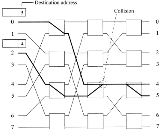
fabric. This field, which has log2N bits for unicast cells or N bits for multicastrbroadcast cells, is used to navigate the cells to their destination output ports. Each bit of the output port address field is examined by each stage of the switch element. If the bit is 0, the cell is routed to the upper output of the switch element. If the bit is 1, it is routed to its lower output.
Ž .
As shown in Figure 1.4, a cell whose output port address is 5 101 is routed Ž .
to input port 2. The first bit of the output port address 1 is examined by the first stage of the switch element. The cell is routed to the lower output and
Ž .
goes to the second stage. The next bit 0 is examined by the second stage, and the cell is routed to the upper output of the switch element. At the last
Ž .
stage of the switch element, the last bit 1 is examined and the cell is routed to its lower output, corresponding to output port 5. Once the cell arrives at the output port, the output port address is removed.
Fig. 1.4 An example of self-routing in a delta network.
1.2 IP ROUTER SYSTEMS
The Internet protocol corresponds to layer 3 as defined in the OSI reference model. The Internet, as originally conceived, offers best-effort data delivery. In contrast to ATM, which is a connection-oriented protocol, IP is a connec-tionless protocol. A user sends IP packets to IP networks without setting up any connection. As soon as a packet arrives at an IP router, the router decides to which output link the packet is to be routed, based on its IP address in the packet overhead, and transmits it to the output link.
To meet the demand for QoS for IP networks, the Internet Engineering
Ž .
Task Force IETF has proposed many service models and mechanisms,
Ž .
including the integrated servicesrresource reservation protocol RSVP Ž .
model, the differentiated services DS model, MPLS, traffic engineering, w x
and constraint-based routing 2 . These models will enhance today’s IP networks to support a variety of service applications.
1.2.1 Functions of IP Routers
IP routers’ functions can be classified into two categories, datapath functions w x
and control functions 1 .
The datapath functions are performed on every datagram that passes through the router. These include the forwarding decision, switching through the backplane, and output link scheduling. When a packet arrives at the forwarding engine, its destination IP address is first masked by the subnet
Ž .
IP ROUTER SYSTEMS 9
Ž .
port numbers source and destination , and type of protocol: total 104 bits. Ž Based on the result of classification, packets may be either discarded
fire-.
wall application or handled at different priority levels. Then, the time-to-live ŽTTL value is decremented and a new header checksum is calculated. Once. the packet header is used to find an output port, the packet is delivered to the output port through a switch fabric. Because of contention by multiple packets destined for the same output port, packets are scheduled to be delivered to the output port in a fair manner or according to their priority levels.
The control functions include the system configuration, management, and exchange of routing table information. These are performed relatively infre-quently. The route controller exchanges the topology information with other
Ž
routers and constructs a routing table based on a routing protocol e.g., RIP .
and OSPF . It can also create a forwarding table for the forwarding engine. Since the control function is not processed for each arriving packet, it does not have a speed constraint and is implemented in software.
1.2.2 Architectures of IP Routers
1.2.2.1 Low-End Routers In the architecture of the earliest routers, the forwarding decision and switching function were implemented in a central CPU with a shared central bus and memory, as shown in Figure 1.5. These functions are performed based on software. Since this software-based struc-ture is cost-effective, it is mainly used by low-end routers. Although CPU performance has improved with time, it is still a bottleneck to handle all the packets transmitted through the router with one CPU.
Fig. 1.6 Medium-size router structure.
1.2.2.2 Middle-Size Routers To overcome the limitation of one central CPU, medium-size routers use router structure where each line card has a CPU and memory for packet forwarding, as shown in Figure 1.6. This structure reduces the central CPU load, because incoming packets are processed in parallel by the CPU associated with each line card, before they are sent through the shared bus to the central CPU and finally to the memory of the destined output line card. However, when the number of ports and the port speed increase, this structure still has a bottleneck at the central CPU and shared bus.
1.2.2.3 High-End Routers In current high-performance routers, the for-warding engine is implemented in each associated ingress line card, and the switching function is implemented by using switch-fabric boards. As shown in Figure 1.7, a high-performance router consists of a route controller, forward-ing engine, switch fabric, and output port scheduler. In this structure, multiple line cards can communicate with each other. Therefore, the router throughput is improved.
Once a packet is switched from an ingress line card to an egress line card, it is usually buffered at the output port that is implemented in the egress line card. This is because multiple packets may be destined for the same output port at the same time. Only one packet can be transmitted to the network at any time, and the rest of them must wait at the output buffer for the next transmission round. In order to provide differentiated service for different flows, it is necessary to schedule packets according to their priority levels or the allocated bandwidth. There may also be some buffer management, such
Ž .
as random early detection RED , to selectively discard packets to achieve
Ž .
IP ROUTER SYSTEMS 11
Fig. 1.7 High-end router structure.
For high-performance routers, datapath functions are most often imple-mented in hardware. If any datapath function cannot be completed in the interval of the minimum packet length, the router will not be able to operate at so-called wire speed, nor accommodate all arriving shortest packets at the same time.
Packets can be transferred across the switch fabric in small fixed-size data units, or as variable-length packets. The fixed-size data units are called cells Žthey do not have to be the same length as in ATM, 53 bytes . For the former. case, each variable-length packet is segmented into cells at the input ports of the switch fabric and reassembled to that packet at the output ports. To design a high-capacity switch fabric, it is highly desirable to transfer packets in cells, for the following reasons. Due to output port contention, there is
Ž
usually an arbiter to resolve contention among the input packets except for output-buffered switches, since all packets can arrive at the same output port simultaneouslyᎏthough, due to the memory speed constraint, the switch
.
capacity is limited . For the case of delivering cells across the switch fabric, scheduling is based on the cell time slot. At the beginning of a time slot, the arbiter will determine which inputs’ cells can be sent to the switch fabric. The
Ž .
have packets destined for it. The second alternative is to transfer the packet in a cell-based fashion with the constraint that cells that belong to the same packet will be transmitted to the output port consecutively, and not inter-leaved with other cells. The differences between these two options have to do with event-driven vs. slot-driven arbitration. In the case of variable-length packets, the throughput is degraded, especially when supporting multicast services. Although the implementations of both alternatives are different, the basic cell transmission mechanisms are the same. Therefore, we describe an example of the variable-length-based operation by considering the first alter-native for simplicity.
The first alternative starts the arbitration cycle as soon as a packet is completely transferred to the output port. It is difficult to have parallelism for arbitration and transmission, due to the lack of knowledge of when the arbitration can start. Furthermore, when a packet is destined for multiple output ports by taking advantage of the replication capability of the switch
Ž .
fabric e.g., crossbar switch , the packet has to wait until all desired output ports become available. Consider a case where a packet is sent to output ports x and y. When output x is busy in accepting a packet from another input and output y is idle, the packet will not be able to send to output y until port x becomes available. As a result, the throughput for port y is degraded. However, if the packet is sent to port y without waiting for port x becomes available, as soon as port x becomes available, the packet will not be able to send to port x, since the remaining part of the packet is being sent to port y. One solution is to enable each input port to send multiple streams, which will increase the implementation complexity. However, if cell switching is used, the throughput degradation is only a cell slot time, as oppose to, when packet switching is used, the whole packet length, which can be a few tens or hundreds of cell slots.
1.2.2.4 Switch Fabric for High-End IP Routers Although most of today’s low-end to medium-size routers do not use switch fabric boards, high-end backbone IP routers will have to use the switch fabric as described in Section 1.2.2.3 in order to achieve the desired capacity and speed as the Internet traffic grows. In addition, since fixed-size cell-switching schemes achieve higher throughput and simpler hardware design, we will focus on the switch architecture using cell switching rather than packet switching.
Therefore, the high-speed switching technologies described in this book are common to both ATM switches and IP routers. The terms of packet switches and ATM switches are interchangeable. All the switch architectures discussed in this book deal with fixed-length data units. Variable-length packets in IP routers, Ethernet switches, and frame relay switches, are
Ž
usually segmented into fixed-length data units not necessarily 53 bytes like .
DESIGN CRITERIA AND PERFORMANCE REQUIREMENTS 13 Differences between ATM switches and IP routers systems lie in their line cards. Therefore, both ATM switch systems and IP routers can be con-structed by using a common switch fabric with appropriate line cards.
1.3 DESIGN CRITERIA AND PERFORMANCE REQUIREMENTS
Several design criteria need to be considered when designing a packet switch architecture. First, the switch should provide bounded delay and small cell loss probability while achieving a maximum throughput close to 100%. Capability of supporting high-speed input lines is also an important criterion for multimedia services, such as video conferencing and videophone. Self-routing and distributed control are essential to implement large-scale switches. Serving packets based on first come, first served provides correct packet sequence at the output ports. Packets from the same connection need to be served in sequence without causing out of order.
Bellcore has recommended performance requirements and objectives for Ž . w x
broadband switching systems BSSs 3 . As shown in Table 1.1, three QoS classes and their associated performance objectives are defined: QoS class1, QoS class 3, and QoS class 4. QoS class 1 is intended for stringent cell loss applications, including the circuit emulation of high-capacity facilities such as DS3. It corresponds to service class A, defined by ITU-T study group XIII. QoS class 3 is intended for low-latency, connection-oriented data transfer applications, corresponding to service class C in ITU-T study group XIII. QoS Class 4 is intended for low-latency, connectionless data transfer applica-tion, corresponding to service class D in ITU-T study group XIII.
The performance parameters used to define QoS classes 1, 3, and 4 are Ž . cell loss ratio, cell transfer delay, and two-point cell delay variation CDV . The values of the performance objectives corresponding to a QoS class
Ž . Ž
depend on the status of the cell loss priority CLP bit CLPs0 for high
TABLE 1.1 Performance Objective across BSS for ATM Connections Delivering Cells to an STS-3c or STS-12c Interface
Performance Parameter CLP QoS 1 QoS 3 QoS 4
y10 y7 y7
Cell loss ratio 0 -10 -10 -10
a
Cell loss ratio 1 NrS NrS NrS
b
Ž .
Cell transfer delay 99th percentile 1r0 150s 150s 150s y10
Ž .
Cell delay variation 10 quantile 1r0 250s NrS NrS
y7
Ž .
Cell delay variation 10 quantile 1r0 NrS 250s 250s
a
NrS not specified. b
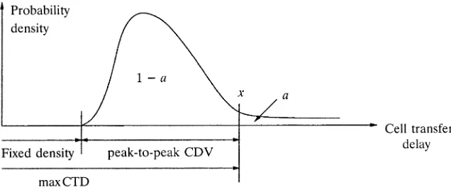
Fig. 1.8 Distribution of cell transfer delay.
.
priority, and CLPs1 for low priority , which is initially set by the user and can be changed by a BSS within the connection’s path.
Figure 1.8 shows a typical distribution of the cell transfer delay through a switch node. The fixed delay is attributed to the delay of table lookup and
Ž . other cell header processing, such as header error control HEC byte examination and generation. For QoS classes 1, 3, and 4, the probability of
Ž .
cell transfer delay CTD greater than 150 s is guaranteed to be less than
w x
1y0.99, that is, Prob CTD)150 s -1y99%. For this requirement, as1% and xs150 s in Figure 1.8. The probability of CDV greater than 250 s is required to be less than 10y10 for QoS class 1, that is,
w x y10
Prob CDV)250 s -10 .
REFERENCES
1. N. McKeown, ‘‘A fast switched backplane for a gigabit switched router,’’Business Commun. Re®., vol. 27, no. 12, Dec. 1997.
2. X. Xiao and L. M. Ni, ‘‘Internet QoS: a big picture,’’ IEEE Network, pp. 8᎐18,
MarchrApril 1999.
Ž .
Broadband Packet Switching Technologies: A Practical Guide to ATM Switches and IP Routers
H. Jonathan Chao, Cheuk H. Lam, Eiji Oki Copyright䊚2001 John Wiley & Sons, Inc.
Ž . Ž .
ISBNs: 0-471-00454-5 Hardback ; 0-471-22440-5 Electronic
CHAPTER 2
BASICS OF PACKET SWITCHING
This chapter discusses the basic concepts in designing an ATM switch. An ATM switch has multiple inputroutput ports, each connecting to another port of an ATM switch or an ATM terminal. An ATM terminal can be a personal computer, a workstation, or any other equipment that has an ATM
Ž .
network interface card NIC . The physical layer of interconnecting ATM Ž
switches or ATM terminals can be SONET such as OC-3c, OC-12c, OC-48,
. Ž .
or OC-192 or others such as T1 or T3 . Physical layer signals are first terminated and cells are extracted for further processing, such as table lookup, buffering, and switching. Cells from different places arrive at the input ports of the ATM switch. They are delivered to different output ports according to their labels, merged with other cell streams, and put into physical transmission frames. Due to the contention of multiple cells from different input ports destined for the same output port simultaneously, some cells must be buffered while the other cells are transmitted to the output ports. Thus, routing cells to the proper output ports and buffering them when they lose contention are the two major functions of an ATM switch.
Traditional telephone networks use circuit switching techniques to estab-lish connections. In the circuit switching scheme, there is usually a central-ized processor that determines all the connections between input and output ports. Each connection lasts on average 3 min. For an N=N switch, the time required to make each connection is 180 seconds divided by N. For instance, suppose N is 1000. The connection time is 180 ms, which is quite relaxed for most of switch fabrics using current technology, such as CMOS crosspoint switch chips. However, for ATM switches, the time needed to
configure the inputroutput connections is much more stringent, because it is based on the cell time slot. For instance, for the OC-12c interface, each cell slot time is about 700 ns. For an ATM switch with 1000 ports, the time to make the connection for each inputroutput is 700 ps, which is very challeng-ing for existchalleng-ing technology. Furthermore, as the line bit rate increases Že.g., with OC-48c and the number of the switch ports increases, the time. needed for each connection is further reduced. As a result, it is too expensive to employ centralized processors for ATM switches.
Thus, for ATM switches we do not use a centralized connection processor to establish connections. Rather, a self-routing scheme is used to establish inputroutput connections in a distributed manner. In other words, the switch fabric has the ability to route cells to proper output ports, based on the physical output port addresses that are attached in the front of each cell. One switch fabric that has self-routing capability is called the banyan switch. It will be discussed in more detail in Chapter 5.
In addition to the routing function to the ATM switch, another important function is to resolve the output port contention when more than one cell is destined for the same output port at the same time. There are several contention-resolution schemes that have been proposed since the first ATM
Ž
switch architecture was proposed in early 1980s the original packet switch was called a high-speed packet switch; the term ATM was not used until late
.
1980 . One way to resolve the contention is to allow all cells that are destined for the same output port to arrive at the output port simultaneously. Since only one cell can be transmitted via the output link at a time, most cells are queued at the output port. A switch with such architecture is called an
output-buffered switch. The price to pay for such scheme is the need for operating the switch fabric and the memory at the output port at a rate N
times the line speed. As the line speed or the switch port number increases, this scheme can have a bottleneck. However, if one does not allow all cells to go to the same output port at the same time, some kind of scheduling scheme, called an arbitration scheme, is required to arbitrate the cells that are destined for the same output port. Cells that lose contention will need to wait at the input buffer. A switch with such architecture is called an input-buffered
switch.
The way of handling output contention will affect the switch performance, complexity, and implementation cost. As a result, most research on ATM switch design is devoted to output port contention resolution. Some schemes are implemented in a centralized manner, and some in a distributed manner. The latter usually allows the switch to be scaled in both line rate and switch size, while the former is for smaller switch sizes and is usually less complex and costly.
SWITCHING CONCEPTS 17
the allocated bandwidth to meet each connection’s delayrthroughput re-quirements. Cells or packets are usually timestamped with values and trans-mitted with an ascending order of the timestamp values. We will not discuss such scheduling in this book, but rather focus on the scheduling to resolve output port contention.
In addition to scheduling cells to meet the delay᎐throughput requirement at the output ports, it is also required to implement buffer management at the input or output ports, depending on where the buffer is. The buffer management discards cells or packets when the buffer is full or exceeds some predetermined thresholds. The objectives of the buffer management are to meet the requirements on cell loss rate or fairness among the connections, which can have different or the same loss requirements. There is much research in this area to determine the discarding policies. Some of them will push out the cells or packets that have been stored in the buffer to meet the loss or fairness objectives, which is usually more complex than the scheme that blocks incoming cells when the buffer occupancy exceeds some thresh-olds. Again this book will focus on the switch fabric design and performance studies and will not discuss the subject of buffer management. However, when designing an ATM switch, we need to take into consideration the potential need for performing packet scheduling and buffer management. The fewer locations of the buffers on the data path, the less such control is required, and thus the smaller the implementation cost.
Section 2.1 presents some basic ATM switching concepts. Section 2.2 classifies ATM switch architectures. Section 2.3 describes performance of typical basic switches.
2.1 SWITCHING CONCEPTS
2.1.1 Internal Link Blocking
Fig. 2.1 Internal blocking in a delta network: two cells destined for output ports 4 and 5 collide.
2.1.2 Output Port Contention
Output port contention occurs when two or more cells arrive from dif-ferent input ports and are destined for the same output port, as shown in Figure 2.2. A single output port can transmit only one cell in a time slot; thus the other cells must be either discarded or buffered. In the output-buffered switches, a buffer is placed at each output to store the multiple cells destined for that output port.
SWITCHING CONCEPTS 19
2.1.3 Head-of-Line Blocking
Another way to resolve output port contention is to place a buffer in each input port, and to select only one cell for each output port among the cells destined for that output port before transmitting the cell. This type of switch is called the input-buffered switch. An arbiter decides which cells should be chosen and which cells should be rejected. This decision can be based on cell priority or timestamp, or be random. A number of arbitration mechanisms have been proposed, such as ring reservation, sort-and-arbitrate, and route-and-arbitrate. In ring reservation, the input ports are interconnected via a ring, which is used to request access to the output ports. For switches that are based on a sorting mechanism in the switch fabric, all cells requesting the same output port will appear adjacent to each other after sorting. In the route-and-arbitrate approach, cells are routed through the switch fabric and arbiters detect contention at the point of conflict.
A well-known problem in a pure input-buffered switch with
first-in-first-Ž . Ž .
out FIFO input buffers is the head-of-line HOL blocking problem. This happens when cells are prevented from reaching a free output because of other cells that are ahead of it in the buffer and cannot be transmitted over the switch fabric. As shown in Figure 2.3, the cell behind the HOL cell at input port 0 is destined for an idle output port 1. But it is blocked by the HOL cell, which failed a transmission due to an output contention. Due to the HOL blocking, the throughput of the input buffered switch is at most
w x
58.6% for random uniform traffic 5, 7 .
2.1.4 Multicasting
To support videoraudio conference and data broadcasting, ATM switches should have multicast and broadcast capability. Some switching fabrics achieve multicast by first replicating multiple copies of the cell and then routing each
copy to their destination output ports. Other switches achieve multicast by utilizing the inherent broadcasting nature of the shared medium without
w x
generating any copies of ATM cells 3 . Details will be discussed later in the book.
2.1.5 Call Splitting
Several call scheduling disciplines have been proposed for the multicast function, such as one-shot scheduling, strict-sense call splitting, and
wide-w x
sense call splitting 1 . One-shot scheduling requires all the copies of the Ž . same cell to be transmitted in the same time slot. Strict-sense SS call
Ž .
splitting and wide-sense WS call splitting permit the transmission of the cell to be split over several time slots. For real-time applications, the delay difference among the receivers caused by call splitting should be bounded. A matrix is introduced to describe the operation of the scheduling algorithm,
Ž .
as shown in Figure 2.4, where each row column corresponds to an input line Žoutput line of the switch. With the multicast feature each row may contain. two or more 1’s rather than a single 1 in the unicast case. At each time slot only one cell can be selected from each column to establish a connection.
SWITCH ARCHITECTURE CLASSIFICATION 21
2.1.5.1 One-Shot Scheduling In a one-shot scheduling policy, all copies of the same cell must be switched successfully in one time slot. If even one copy loses the contention for an output port, the original cell waiting in the input queue must try again in the next time slot. It is obvious that this
Ž .
strategy favors cells with fewer copies i.e., favors calls with fewer recipients , and more often blocks multicast cells with more copies.
2.1.5.2 Strict-Sense Call Splitting In one-shot discipline, if only one
Ž .
copy loses contention, the original cell all its copies must retry in the next time slot, thus degrading the switch’s throughput. This drawback suggests transmitting copies of the multicast cell independently. In SS call splitting, at most one copy from the same cell can be transmitted in a time slot. That is, a multicast cell must wait in the input queue for several time slots until all of its copies have been transmitted. If a multicast cell has K copies to transmit, it needs at least K time slots to transmit them. Statistically this algorithm results in a low throughput when the switch is underloaded during light traffic, since the algorithm does not change dynamically with the traffic pattern.
2.1.5.3 Wide-Sense Call Splitting The case of light traffic should be considered when only one active input line has a multicast cell to be transmitted and all output ports are free. In this case, SS call splitting only allows one cell to be transmitted per time slot, resulting in a low utilization. WS call splitting was proposed to allow more than one copy from the same multicast cell to gain access to output ports simultaneously as long as these output ports are free.
It is clear that one-shot discipline has the lowest throughput performance among all three algorithms; however, it is easiest to implement. SS call splitting performs better than one-shot in the heavy traffic case, but it seems rigid in the light traffic case and results in a low utilization. WS call splitting has the advantage of the full use of output trunks, allowing the multicast cell to use all free output ports, which results in a higher throughput.
2.2 SWITCH ARCHITECTURE CLASSIFICATION
ATM switches can be classified based on their switching techniques into two
Ž . Ž .
Fig. 2.5 Classification of ATM switching architectures.
2.2.1 Time-Division Switching
In TDS, there is a single internal communication structure, which is shared by all cells traveling from input ports to output ports through the switch. The internal communication structure can be a bus, a ring, or a memory. The main disadvantage of this technique is its strict capacity limitation of the internal communication structure. However, this class of switch provides an advantage in that, since every cell flows across the single communica-tion structure, it can easily be extended to support multicastrbroadcast operations.
2.2.1.1 Shared-Medium Switch In a shared-medium switch, cells arriv-ing at input ports are time-division multiplexed into a common high-speed medium, such as a bus or a ring, of bandwidth equal to N times the input line rate. The throughput of this shared medium determines the capacity of the entire switch. As shown in Figure 2.6, each output line is connected to the shared high-speed medium via an interface consisting of an address filter ŽAF and an output FIFO buffer. The AF examines the header part of the. incoming cells, and then accepts only the cells destined for itself. This decentralized approach has an advantage in that each output port can operate independently and can be built separately. However, more hardware logic and more buffers are required to provide the separate interface for each output port.
SWITCH ARCHITECTURE CLASSIFICATION 23
Fig. 2.6 Shared-medium switching architecture.
in the following FIFO. One disadvantage of this structure is that the switch size N is limited by the memory speed. In particular, when all N input cells are destined for the same output port, the FIFO may not be able to store all
Ncells in one time slot if the switch size is too large or the input line rate is too high. Another disadvantage is the lack of memory sharing among the FIFO buffers. When an output port is temporarily congested due to high traffic loading, its FIFO buffer is filled and starts to discard cells. Meanwhile, other FIFO buffers may have plenty of space but cannot be used by the congested port. As a result, a shared-memory switch, as described below, has a better buffer utilization.
Ž
Examples of shared-medium switches are NEC’s ATOM ATM output
. w x Ž
buffer modular switch 13 , IBM’s PARIS packetized automated routing . w x
integrated system switch 2 , and Fore System’s ForeRunner ASX-100 switch
w x3 .
2.2.1.2 Shared-Memory Switch In a shared-memory switch, as shown in Figure 2.7, incoming cells are time-division multiplexed into a single data stream and sequentially written to the shared memory. The routing of cells is accomplished by extracting stored cells to form a single output data stream, which is in turn demultiplexed into several outgoing lines. The memory addresses for both writing incoming cells and reading out stored cells are provided by a control module according to routing information extracted from the cell headers.
Fig. 2.7 Basic architecture of shared-memory switches.
memory among the ports: complete partitioningand full sharing. In complete partitioning, the entire memory is divided into Nequal parts, where N is the number of inputroutput ports, and each part is assigned to a particular output port. In full sharing, the entire memory is shared by all output ports without any reservation. Some mechanisms, such as putting an upper and a lower bound on the memory space, are needed to prevent monopolization of the memory by some output ports.
Like shared-medium switches, shared-memory switches have the disadvan-tage that the memory access speed limits the switch size; furthermore, the control in the shared-memory switches is more complicated. Because of its better buffering utilization, however, the shared-memory type is more popu-lar and has more variants than the shared-medium type. Detailed discussions about those variants and their implementations are given in Chapter 4.
Examples of shared-memory switches are Toshiba’s 8=8 module on a
w x w x
single chip 12 and Hitachi’s 32=32 module 8 .
2.2.2 Space-Division Switching
SWITCH ARCHITECTURE CLASSIFICATION 25
SDS switches are classified based on the number of available paths between any inputroutput pair. In single-path switches, only one path exists for any inputroutput pair, while in multiple-pathswitches there is more than one. The former has simpler routing control than the latter, but the latter has higher fault tolerance.
2.2.2.1 Single-Path Switches Single path switches are classified into
crossbar-based switches, fully interconnected switches, and banyan-based w x
switches 10 .
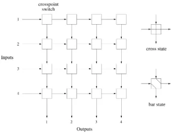
( )a Crossbar Switches A crossbar switch is schematically shown in Figure 2.8 for Ns4, where horizontal lines represent the inputs to the switch, and vertical lines represent the outputs. Basically, an N=N crossbar switch consists of a square array of N2 individually operated crosspoints, one corresponding to each input᎐output pair. Each crosspoint has two possible
Ž .
states: cross default and bar. A connection between input port iand output Ž .
[image:41.612.46.385.312.575.2]port j is established by setting the i, jth crosspoint switch to the bar state while letting other crosspoints along the connection remain the cross state. The bar state of a crosspoint can be triggered individually by each incoming
cell when its destination matches with the output address. No global informa-tion about other cells and their destinainforma-tions is required. This property is called the self-routing property; by it the control complexity is significantly reduced in the switching fabric, as the control function is distributed among all crosspoints.
Crossbar switches have three attractive properties: they are internally nonblocking, simple in architecture, and modular. However, they are complex in terms of the number of the crosspoints, which grows as N2. The arbitra-tion that is to choose a winner for every output in each time slot can also become a system bottleneck as the switch size increases.
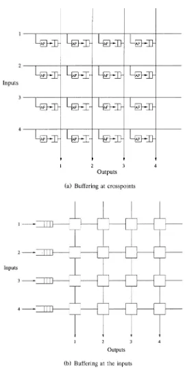
Ž . There are three possible locations for the buffers in a crossbar switch: a
Ž . Ž .
at the crosspoints in the switch fabric, b at the inputs of the switch, and c at the inputs and outputs of the switch. Each one has its advantages and disadvantages.
Ž .
Figure 2.9 a depicts the strategy of buffering cells at the crosspoints. The Ž .
bus matrix switch BMX proposed by Fujitsu is an example of this type of
w x
switch 11 . There is an AF and a buffer at each crosspoint. The AF accepts the cells destined for the corresponding output port and stores them in the buffer. Cells waiting in the buffers on the same column are arbitrated to the output port with one cell per slot. The switch is work-conserving, and does not suffer the throughput limitation incurred with input buffering. In a sense, it is similar to achieving output queuing, with the difference that the queue for each output is distributed over N buffers. As there is no sharing among the N buffers, the total memory required for a given loss rate is greater than
Ž .
that required for output queuing e.g., in the shared-medium case . As the buffer memory typically requires much more real estate in a chip than crosspoint logic, including the crosspoint buffers in the chip would severely limit the number of crosspoints in the chip.
Ž .
Figure 2.9 b depicts the input queuing approach. Separating the buffers from the crosspoints is desirable from the viewpoint of layout and circuit compactness. A cell arriving at an input first enters the buffer, waiting its turn to be switched over the fabric. With distributed contention resolution, conflicts are resolved individually at crosspoints. When a cell reaches a crosspoint that has already been set by an earlier cell, or it loses contention to another contending cell, a blocking signal is generated and sent to the input port. This is to block the transmission of the cell and to keep the cell in the input buffer for later tries. With centralized contention resolution, alternatively, an arbiter is used for each output port to resolve contention, and only one cell destined for an output is allowed to be forwarded to the switch fabric.
The third approach combines the advantages of input buffering and output buffering. The detail is described in Section 2.2.3.
SWITCH ARCHITECTURE CLASSIFICATION 27
Fig. 2.10 A fully interconnected switch.
means of N separate broadcast buses from every input port to all output ports, as shown in Figure 2.10. N separate buffers are required in such a switch, one at each output port. However, if each of these N output buffers in the fully interconnected switch is partitioned and dedicated to each input line, yielding N2 dedicated buffers, it becomes topologically identical with the crosspoint-buffered switch, and thus provides exactly the same perfor-mance and implementation complexity.
The fully interconnected switch operates in a similar manner to the shared-medium switch. A cell from any input port is broadcast to every output port. Thus, cells from several input ports can be simultaneously transmitted to the same output port. Therefore, cell filters and dedicated buffers, one for each output port, are required to filter out the misdelivered cells and to temporarily store the properly destined cells.
However, the fully interconnected switch is different from the shared-medium switch in that the speedup overhead requirement caused by sequen-tial transmission over the shared medium is replaced by the space overhead requirement of the N2 separate broadcast buses. This is considered a disadvantage of the switch type. The advantages of the fully interconnected switch lie in its simple and nonblocking structure, similar to the crossbar-based
w x
switch. The knockout switch is an example of this type of switch 15 .
SWITCH ARCHITECTURE CLASSIFICATION 29
Fig. 2.11 Three different topologies of banyan-based switches.
three isomorphic topologiesᎏdelta, omega, and banyannetworksᎏbelonging to the banyan-based family. All of them offer equivalent performance and are discussed in detail in Chapter 5.
The banyan-based switch provides several advantages: First, it has a complexity of paths and switching elements of order N logN, which makes it much more suitable than the crossbar-based and the fully interconnected switch, whose complexity is of order N2, for the construction of large switches. Self-routing is also an attractive feature in that no control mecha-nism is needed for routing cells. Routing information is contained within each cell, and it is used while the cell is routed along the path. Parallel structure of the switch provides a benefit in that several cells on different paths can be processed simultaneously. Due to their modular and recursive structure, large-scale switches can be built by using elementary switching elements without modifying their structures. This can be appropriately real-ized by VLSI implementation.
The main drawback of the banyan-based switch is that it is an internally blocking switch. Its performance degrades rapidly as the size of the switch
Ž .
increases. The performance may be improved if M=M M)2 switching elements are employed instead of 2=2 switching elements. This leads to the class of delta-basedswitches.
The delta-based switch is a family of self-routing switches constructed from M=M switching elements with a single path between any input and output port. While the performance of the delta-based switch can be signifi-cantly better than that of the banyan-based switch, it is still a blocking switch. The performance of the switch is reduced due to internal contention. This can be improved by increasing the speed of internal links within the switch with respect to that of input and output ports or by introducing buffers into the switching elements.
2.2.2.2 Multiple-Path Switches Multiple-path switches are classified as
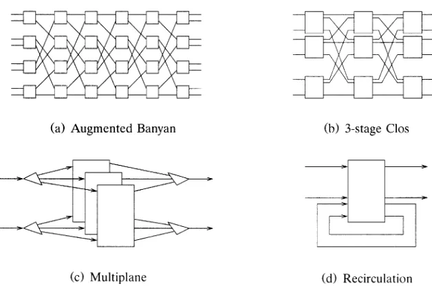
augmented banyanswitches,Clos switches, multiplaneswitches, and recircula
Fig. 2.12 Multiple-path space-division switches.
( )a Augmented Banyan Switches In a re