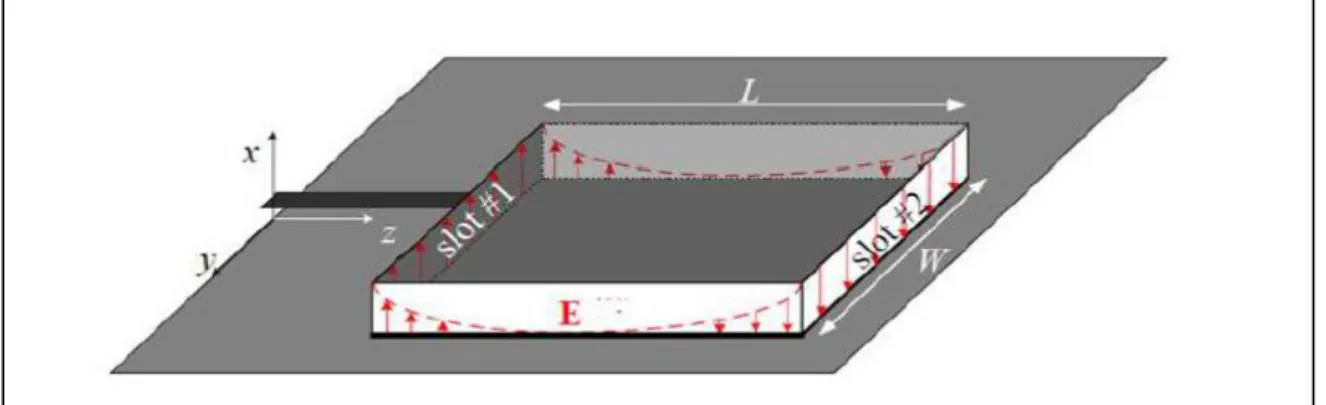
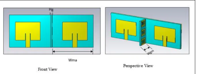
The metasurface superstrate-based antenna designs are formulated by suspending a metasurface superstrate over the 2-port microstrip antenna. In the first metasurface-based antenna design, a single metasurface wall is placed vertically between the two microstrip antenna elements.
Introduction
- Background
- Problem statement
- Literature Review
- Research Aim and Objectives
- Research significance
- Methodological approach
- Thesis Structure
- Chapter Summary
Achieving a maximum mutual coupling reduction of 8 dB. In [36], a dumbbell-like pattern is carved on the ground plane between two parallel planar inverted-F antennas (PIFAs). This research attempts to reduce the intercoupling of a 2-port MIMO microstrip antenna using metasurface technology.
![Figure 1:1 Comparison between SISO and MIMO channel capacity [4].](https://thumb-ap.123doks.com/thumbv2/pubpdfnet/10329483.0/16.893.111.662.661.952/figure-comparison-siso-mimo-channel-capacity.webp)
Microstrip Antenna Design Theory
Introduction
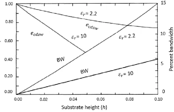
It can be seen from the figure that an increase in the dielectric constant results in a decrease in the bandwidth. From this we can conclude that a dielectric material with a low dielectric constant gives a higher bandwidth and efficiency.
![Table 2.1: Microstrip antenna applications in various systems [57].](https://thumb-ap.123doks.com/thumbv2/pubpdfnet/10329483.0/26.893.110.696.148.456/table-microstrip-antenna-applications-in-various-systems.webp)
Microstrip Antenna Feeding Methods
- Microstrip Line
- Co-axial Feed
- Aperture Coupled Microstrip Feed
- Proximity Coupled Microstrip Feed
The supply line is electromagnetically coupled to the patch via an electrical slot or opening slot cut into the ground plane. The disadvantages that this feeding method offers are that it results in an increase in antenna thickness and its manufacturing process is complex due to the two dielectric substrates that require alignment.
Microstrip Methods of Analysis
- Transmission Line Model
- Cavity Model
The longitudinal expansion (∆𝐿) can be calculated as a function of the height of the substrate (h), the width of the patch (W) and the effective dielectric constant of the substrate (𝜀𝑟𝑒𝑓𝑓), it can be calculated by using equation ( 2.2) below [55, 59]. The width of the microstrip spot that results in large radiation efficiency is given by equation (2.8) [55].
Microstrip Antenna Design Parameters
- Return Loss
- Gain and Directivity
- Radiation Pattern
- Input Impedance and Impedance Matching
- Bandwidth
- Antenna Polarization
- Substrate Properties
- Effect of Finite Ground Plane
The first null beam width (FNBW) can be described as, an angular separation between the first zero points of the radiation pattern. Half power beam width (HPBW) can be described as an angular width at half power of the antenna radiation pattern. Input impedance can be defined as "the resistance presented by an antenna at its terminals or the ratio of voltage to current at a pair of terminals or the ratio of the corresponding electric to magnetic field components at a point" [56].
If we assume that the antenna is connected to a generator with an internal impedance, then the impedance of the generator can be expressed by Eq. Using modal expansion analysis, the input resistance of the inserted feed can be approximated to be given by Eq. The input impedance seen from the start of the quarter-wavelength t-line can be expressed by Eq.
It can be described as "The property of an electromagnetic wave that describes the time-varying direction and relative magnitude of the electric field vector" [56]. The direction of vibration in free space of the electric field component is called the polarization of an antenna.
![Figure 2:12: Antenna radiation pattern showing lobes and beam width [70].](https://thumb-ap.123doks.com/thumbv2/pubpdfnet/10329483.0/42.893.108.566.106.454/figure-antenna-radiation-pattern-showing-lobes-beam-width.webp)
Chapter Summary
The aforementioned microstrip methods of analysis only consider an infinite ground plate, but for practical purposes such as antenna fabrication, the size of the ground plate must be finite. Unfortunately, this increases the simulation time because both the ground plate and the patch need to be analyzed. The obtained results were found to be comparable to those of an infinite ground plate [64] when the dimensions of the ground plate are six times larger than the dimensions of the radiating patch.
Metamaterial and Metasurface Design Theory
- Introduction
- Metamaterial Classification
- Single Negative Metamaterials
- Double Negative Metamaterials
- Metasurfaces
- Metasurfaces Classification and Applications
- Chapter Summary
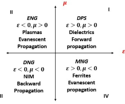
The behavior of any material to applied electromagnetic radiation can be categorized by two electromagnetic parameters, which are magnetic permeability (µ). and electrical permittivity (ε). Double negative (DNG) or left-handed medium (LHM) materials occur when ε < 0 and μ < 0 (permittivity and permeability are both negative), they are not natural materials, i.e. they can be arranged in a quasi-periodic or aperiodic fashion, depending on the wavefronts to be manipulated [86].
The resulting transmission and reflection results are determined by the properties or characteristics of the surface, which can be defined in terms of impedance. Diodes offer capacitance that is voltage dependent, which can be applied at the unit cell gaps to change the capacitance. Like all other materials, they can be categorized according to two electromagnetic parameters, which are magnetic permeability (µ) and electrical permittivity (ε). The most commonly used metamaterials in antenna design and improvement are the single negative metamaterials (SNG) and the double ones. negative metamaterial (DNG).
A metasurface is a two-dimensional structure with properties equivalent to metamaterials and can therefore be used in the same areas as metamaterial structures. They can be classified into three subcategories namely impedance metasurface, Huygens metasurface and dielectric metasurface.
Design of Microstrip Antenna for SISO Systems
- Introduction
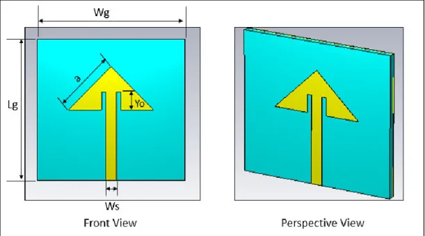
- Triangular Microstrip Antenna
- Antenna Substrate
- Resonant Frequency
- Effective Side Length
- Results
- Conclusion
- Rectangular M-Antenna Design
- Antenna Parameters
- Probe Feed M-Antenna
- Rectangular Inset Feed
- Chapter Summary
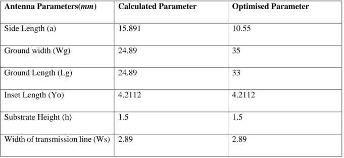
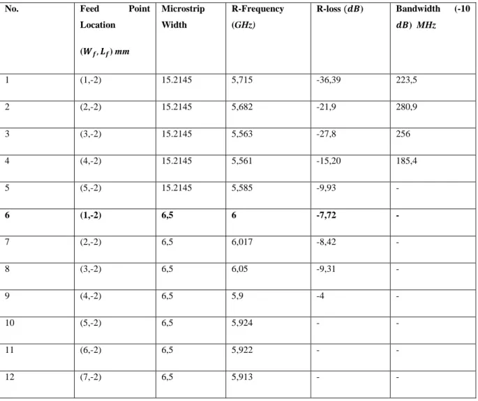
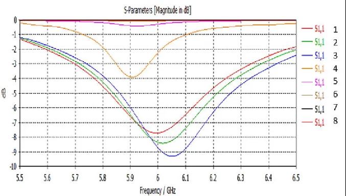
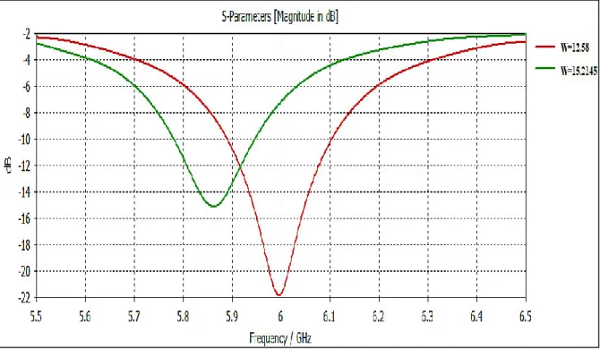
The triangular conductive patch is one of the shapes that has attracted attention recently [61]. The height of the substrate was chosen at 1.5 mm and the thickness of the coating was chosen at 0.035. Comparing No. 1 and No. 6 from the table above, it can be observed that reducing the microstrip width from 15.2145 to 6.5 resulted in a bandwidth of 0 MHz, while also reducing the round-trip loss by up to 5 times.
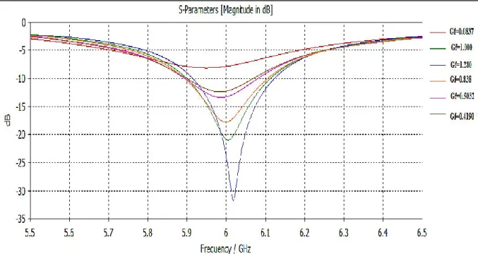
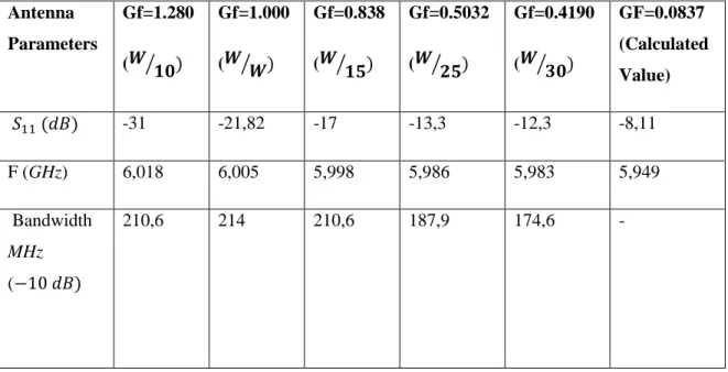
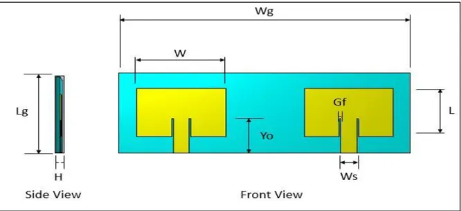
The insertion width and insertion distance can be calculated using the following equations [56]. The characteristic impedance of the microstrip line can be calculated from equation (4.6), for this design the selected impedance is 50 𝑜ℎ𝑚𝑠 . From this equation can be solved for the width of the microstrip line (𝑊𝑂). Where 𝑍𝑐 is the characteristic impedance of the microstrip line and 𝑊𝑂 is the width of the microstrip line. The rest of the values are obtained by taking Gf as the width ratio, i.e.
From the table it can be observed that slit width, insertion point width and transmission line width are the only parameters that are optimized by the paper design. From the above discussion it is evident that the best performing single element antenna is the rectangular insertion microstrip antenna (RIA) because it has the lowest return loss, lowest VSWR, highest bandwidth which is 60% more than that of TIA.
Metasurface based MIMO Microstrip Antennas
Introduction
- Geometry, Results and Discussion
Where port 1 is the port on the left and port 2 is the port on the right. A 2-port microstrip rectangular nested feeder (Antenna 1) is designed in CST microwave studio using the parameters obtained in the single microstrip antenna element designed in Chapter 6. CST microwave studio has a parameter shift function that allows entering the range of the parameter in question and incremental steps for this parameter.
The vector network analyzer was used to measure the reflection coefficients and intercouplings of the fabricated antenna prototype, the results obtained are then compared with the simulated results. The figure shows that the simulated S1.1 parameter is slightly smaller than the measured S1.1 parameter. A slight shift in resonant frequency to the right can also be observed for the measured S2,2 parameter, while the measured S2,1 and S1,2 parameters are slightly less than the simulated S2,1 and S1,2 parameters, respectively.
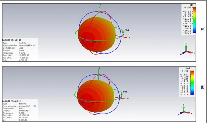
Slight differences can be seen between the simulated S-parameters and the measured S-parameters, these differences can be attributed to solder residue, vector network analyzer calibration, manufacturing and assembly error. It can be observed from the figure that the gain of antenna element 1 was obtained as 4.71 𝑑𝐵 and gain of element 2 was obtained as 4.88 𝑑𝐵.
Metasurface Design
The permittivity and permeability values are derived in the CST microwave studio using the parameters S and shown in Figure 5.8. This engineered metasurface is then used in the unmodified 2-port microstrip antenna, where it introduces a region of positive permittivity and negative permeability.
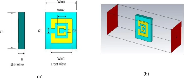
Metasurface based Antenna Design
- Metasurface wall based Antenna Design for M-Coupling Reduction
- Metasurface Superstrate based Antenna for M-Coupling Reduction
- Chapter Summary
This design uses a triple metasurface wall placed vertically between the two radiating antenna elements to reduce coupling between them. Meanwhile, a slight decrease in antenna radiation efficiency of less than 5% can be observed for all three proposed antennas. Single Suspended Metasurface Superstrate for M-Coupling Reduction (Antenna 5) This design uses a single metasurface superstrate suspended on top of the two-element microstrip antenna for mutual coupling reduction.
Dual Suspended Metasurface Superstrate for M-coupling Reduction (Antenna 6) This design uses a dual metasurface superstrate suspended above the two-port microstrip antenna for mutual coupling reduction. It can be observed that both metasurface based antennas drastically reduce the antenna 1 intercoupling across the entire bandwidth. Table 5.6 shows a significant decrease in the overall efficiency of the fifth antenna from 70% to 26%, again emphasizing that antenna 5 is poorly matched.
Table 5.7 shows that the antenna design with a single metasurface wall antenna (Antenna 2) does not reduce mutual coupling. The dual metasurface wall-based design (Antenna 3) and the triple metasurface wall-based design (Antenna 4) shown significant mutual coupling reduction at the center frequency.
Conclusion and Future Work
Conclusion
The second (Antenna 3) and third (Antenna 4) antenna designs on the metasurface wall achieved a mutual coupling reduction of 11 dB and 25 dB, respectively. An antenna design based on a double suspended superstrate metasurface (Antenna 6) achieved a mutual coupling reduction of 22 dB over the entire bandwidth. In addition, it also achieved a 38% increase in bandwidth and a gain increase of 2.09 dB, without the need for additional matching methods.
Therefore, it proved to be the best performing antenna compared to the other four metasurface-based antenna designs. It also shows excellent performance compared to other recent interconnects because it matches well with the highly maintained radiation pattern. This eliminates the need for any additional matching methods, which are undesirable because they increase manufacturing cost and complexity.
Future Works
Yin, "A Meta-Surface Antenna Array Decoupling (MAAD) Method for Mutual Coupling Reduction in a MIMO Antenna System", Sci. Tang et al., "A Metasurface Superstrate for Mutual Coupling Reduction of Large Antenna Arrays", IEEE Access, vol. Alibakhshikenari et al., "Meta-surface wall suppression of mutual coupling between microstrip patch antenna arrays for THz band applications," Prog.
Cui, “Reduction of mutual coupling between densely packed patch antennas using waveguide metamaterials,” IEEE Antennas Wirel. Hartanto, “Mutual coupling reduction using dumbbell defect ground structure for multiband microstrip antenna array,” Prog. Cui, “Reducing the spatial mutual coupling between dual-polarized patch antennas using coupled metamaterial sheets,” Sci.
Ghobadi, "Mutual coupling reduction between very closely spaced patch antennas using low-profile folded split-ring resonators". Quanming, “Reducing mutual coupling between close-packed split-ring resonator (SRR) antenna elements,” 2010 Int.
![Figure 3:4: Incident electromagnetic field (𝐸 ⃗⃗⃗⃗ , 𝐻 1 ⃗⃗⃗⃗ ) 1 being converted to transmitted electromagnetic field (𝐸 ⃗⃗⃗⃗ , 𝐻 2 ⃗⃗⃗⃗ ) [97]](https://thumb-ap.123doks.com/thumbv2/pubpdfnet/10329483.0/58.893.104.493.107.356/figure-incident-electromagnetic-field-𝐸-converted-transmitted-electromagnetic.webp)