Since reliable mmWave access networks are also a prerequisite for the successful roll-out of the next generation (5G) networks, this becomes a technology bottleneck. Spectrum shuffling [8] involves the shuffling of the existing microwave spectrum according to their significance.
Challenges in mmWave Based Systems
Motivation and Research Objectives
-layer-based techniques, which would allow our proposed deadlock mitigation approaches to adapt to low-latency handovers. iii) Network and MAC layer based congestion mitigation solutions available in the literature are not linearly scalable. Therefore, in this thesis, we want to explore some network-centric frameworks that would allow our proposed blocking mitigation solutions to work seamlessly in different network sizes (and configurations) without requiring any additional hardware. iv).
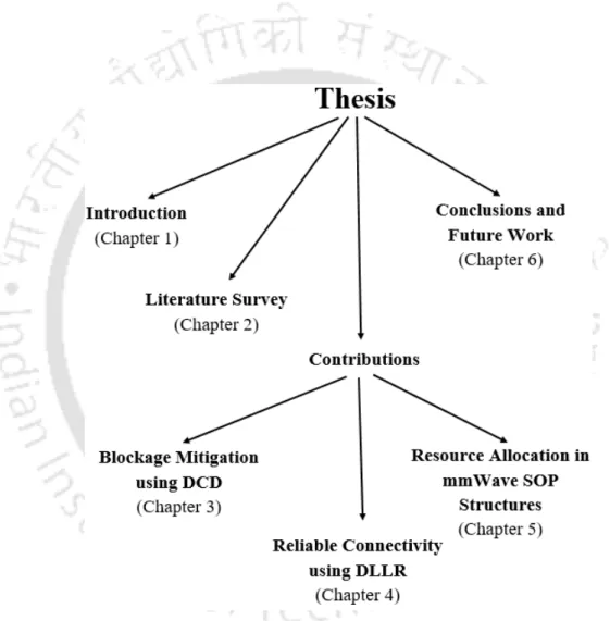
Thesis Contribution
Thesis Organization
It also reviews the literature on various state-of-the-art blockade mitigation techniques, along with their advantages and disadvantages. It also reviews the existing literature and discusses several state-of-the-art congestion mitigation techniques along with their advantages and disadvantages.
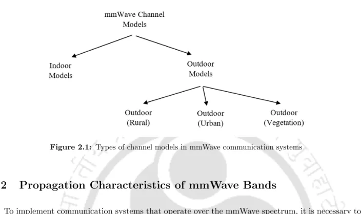
Propagation Characteristics of mmWave Bands
- Path-loss Characteristics in mmWave Bands
- Diffraction Properties in mmWave Bands
- Effect of Human Blockage and Other Factors on mmWave Propagation
- Implication of PHY Layer Characteristics in the MAC Layer
In [38] it was reported that the PLEs for LoS transmissions were identical (i.e. 1.7 and 1.8 respectively) for the 28 GHz and the 73 GHz bands, and for the NLoS transmissions the PLE values were higher than those in the case of LoS scenarios. Due to the high path loss coefficients in the mmWave bands and the limitations on the peak operating power for the wireless devices (according to the Federal Communications Commission (FCC) rules [51]), these systems use antenna arrays and communicate with each other using to make directional rays.
Mitigation of Beam-Blockage in mmWave Systems
Physical Layer Solutions for Blockage Mitigation
These use multiple beams simultaneously between a pair of transceivers to ensure that the link is maintained even when one of the links is blocked. Using a 60 GHz band-based indoor mmWave network scenario, the researchers evaluated the effect of beamwidth matching on beam blocking and observed that optimal beamwidth matching can achieve up to 13 dB gain in received signal strength (RSS). However, in mobile scenarios, the delay in determining the optimal beamwidth can be a bottleneck in terms of maintaining stable connectivity.
Network Layer Solutions for Blockage Mitigation
However, in practical scenarios when a link is blocked, the delay incurred in selecting and re-matching backup NLoS links can often become unacceptably high to maintain continuous communication. As a cost-effective approach, [64] proposed a beam spreading technique and optimization to mitigate beam blockages. Similarly, [68] proposed a Markov Decision Process (MDP)-based framework to model blocking dynamics in mmWave multi-access point architecture and proposed a multi-objective distributed optimization approach to select access point nodes to mitigate beam blocking.
MAC Layer Solutions for Blockage Mitigation
Mitigation of Unreliability and Resource Allocation Issues in mmWave Systems
It then discusses mmWave-based communication systems and discusses their propagation characteristics and limitations in the MAC layer. As discussed in previous sections, beam blocking can also cause reliability and resource allocation problems in mmWave networks. Similarly, in network and MAC-layer solutions, dual link LTE-mmWave is based on a heterogeneous architecture.
DCD Approach for Blockage Mitigation
Static Policy based DCD Approaches
- Maximally Connected Neighbour Approach
- Maximally Stable Neighbour Approach
- Limitations of Static Policy based DCD Approaches
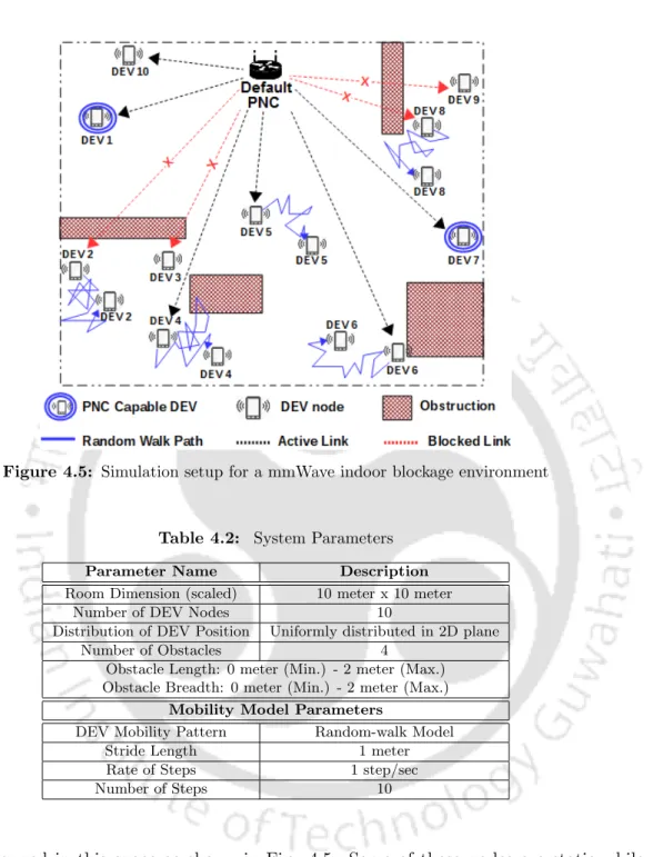
Then, in the second phase of the approach, the default PNC instructs each of the delegable nodes in the set ˜D to perform their own neighbor discovery (according to the provisions of [72]). The standard PNC is aware of the sectors in which the obstacle edges are located. In either case, the visibility of the piconet in relation to the default PNC and the other delegable nodes may be changed (ii) The traffic associated with each of the DEV nodes may vary over time.
DT-MDP Framework for Determination of Optimal Delegation Policy
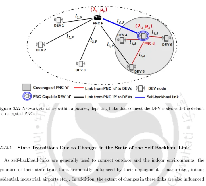
- State Transitions Due to Changes in the State of the Self-Backhaul Link 36
- State Transitions Model for the Combined System
- Determination of State Transition Reward and Optimal Decision Policy 44
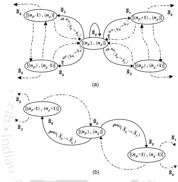
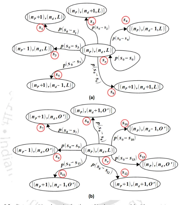
State space (S): During each decision period, the piconet operates in a particular state and the collection of all such system states forms the state space (S) of the network. Here ldi,P indicates the state of the self-recovery link connecting the default and the delegated PNC di. In this case, with respect to the piconet's current load state ¯s0, the system can transition to any of the following states: (a) load state{(nP + 1),(nd)}corresponding to the state transition (¯s0 → s¯1); (b) load state {(nP −1),(nd)} corresponding to the state transition.
Simulation and Results
Simulation Setup
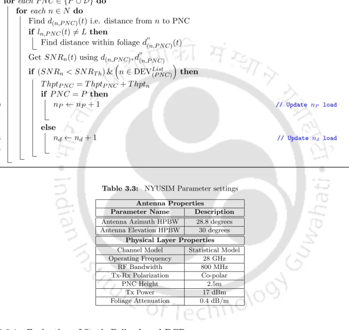
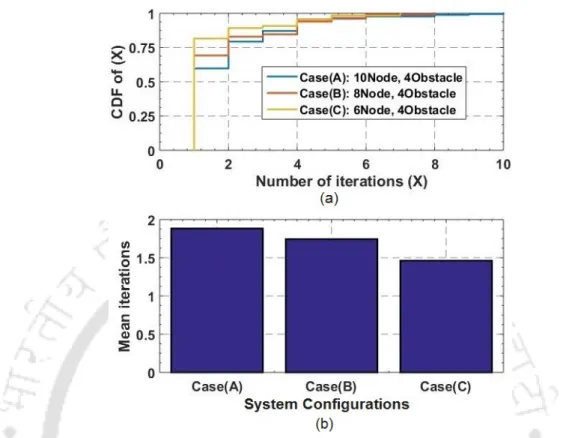
In VIA, the number of iterations needed to reach the optimal value depends on the nature and magnitude of the discount factor (ω). Based on changes in PNC load levels and the state of the self-backhaul link(s), state transition probabilities and their corresponding rewards are then calculated. As a result, all delegation decisions would only be affected by the change in the piconet blocking scenario.
Result Analysis
- Evaluation of Static Policy based DCD
- Evaluation of DT-MDP Framework based DCD
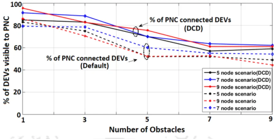
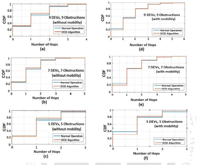
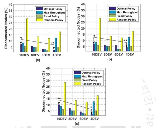
It compares the maximally connected neighbor approach against the default piconet behavior in terms of the percentage of DEVs that are connected to the PNC. 3.8, we plot the node-to-node packet transmission cost distribution (CDF) in terms of the number of hops required to reach a destination node from a given source node, and compare two DCD approaches based on static policies (the maximally connected and the maximally stable neighbor approaches) with respect to default piconet mode. 3.10(a), (b) and (c) show the distribution of the total number of serviced DEVs for different system configurations under residential, urban and micro profiles and industrial profiles, respectively.
Conclusion
The results of extensive simulation testing have shown that the Dynamic Link Level Redundancy (DLLR) approaches can be used to effectively reduce the need for redundant infrastructure in MLC-based block mitigation solutions for efficient use of network resources. In mmWave systems, a wide variety of blockage mitigation solutions use the MLC architectures to address the problem of link dropouts. As discussed in Chapters 2 and 3, most of the prominent network and MAC layer-based approaches to reducing blockages, for example, and some of the physical layer approaches (for example, the beam diversity-based techniques used by MLC architectures to blocking tolerance.
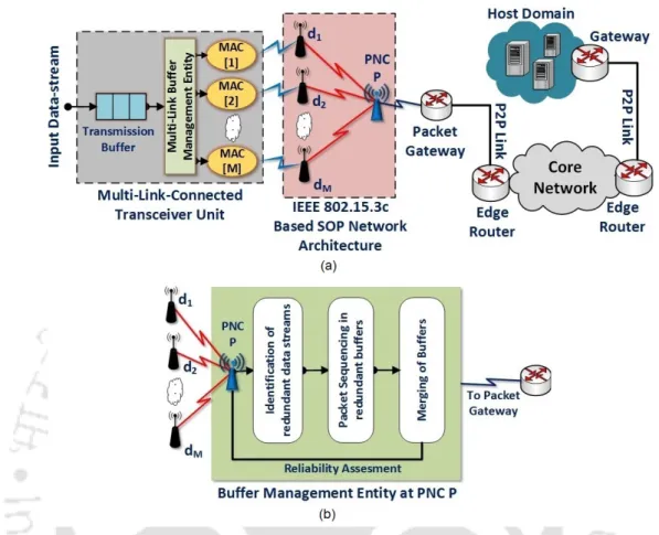
MLC Configuration using IEEE 802.15.3c based SOP Architecture
Frame Structure for Multiple Simultaneous Connectivity
If the PNC accepts the connection request, it generates a DEV ID for the connecting node (with the corresponding group key) and passes it to the connecting device. Upon receiving the response command, the requesting DEV sends another connection request command with the DEV ID shared by the PNC. DEV completes the above process for each of the redundant PNCs using separate MAC addresses to establish the MLC.
Transceiver Design to Support MLC Operation
The main steps in the buffer analysis process at node P are shown in Fig. 4.4(a), it can be observed that, with an increase in redundancy levels, the percentage of successfully transmitted packets increases significantly. 4.4(b) it can be observed that with an increase in the number of redundant links, the equivalent link reliability, which is defined in terms of the average percentage of successfully transferred packets, improves at a linear rate.
DLLR Approaches for Controlling Link Redundancy
System Model
Here, depending on the choice of model parameters (Pr,m and pz(x)), different link states are introduced and denoted using setSL, where SL={sl1, sl2, ., sli}. Similarly, we discretize the traffic associated with each DEV node into K different types and represent each type of traffic using k = 1, ., K different intensities. Then, based on the above mapping and the mapping between SNR threshold and traffic states (TABLE-4.1), a quantitative score is derived for each channel state using (4.4).
Simulation Model
Here, for a given link state li ∈SL, its corresponding SNR threshold is denoted using SN RT h(sli). In this approach, the initial combination of redundant links is the one with the largest number of redundant links. Next, the algorithm evaluates the redundancy combinations of downstream links by removing one link at a time and analyzing the performance against a desired performance threshold. iv) Heuristic-based approach: Here, the combination of redundant links is selected using the heuristic-based approach of Algorithm 5.
Result and Analysis
Furthermore, since the number of feasible redundant options decreases with increasing µT h , it can be observed that the probability of finding an acceptable solution decreases with increasing confidence threshold for all algorithms. 4.8 each of the DC-DLLR approaches achieves the desired reliability threshold by using a different link-level redundancy distribution. It can be observed that the iterative and heuristic approaches achieve the desired redundancy threshold with the maximum number of unused connections.
Conclusion
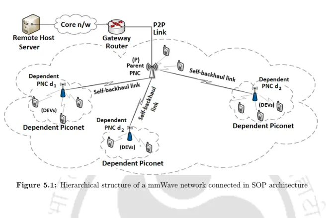
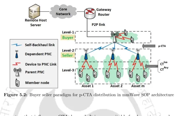
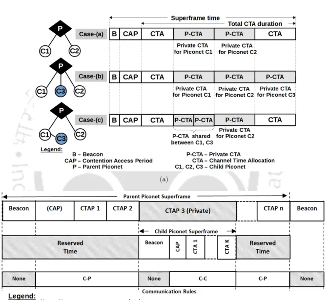
The proposed techniques are based on the concurrently operating piconet (SOP) architecture (operating on IEEE 802.15.3c MAC standard [72]) and use two different methodologies to achieve efficient resource allocation. As discussed in Appendix A.1, the resource allocation mechanism in an SOP structure consists of several dependent PNCs connected to a parent PNC in a hierarchical manner, where the dependent PNCs rely on the parent PNC for a share of its channel time resources. Thus, depending on the requirement of channel time in each of the dependent piconets, the parent PNC distributes its resources using periodically updated pseudo-static-channel-time allocations (p-CTAs).
Description of the p-CTA Assignment Framework
At the dependent PNC's level, all the CTAsy and CTIso requests (as generated by the associated DEVs) are consolidated and the overall channel time request is communicated to the parent PNC as a p-CTA request. Unlike the regular CTAsy and CTIso requests, the pseudo-static/private CTA (p-CTA) allocation requests are communicated occasionally and usually involve reallocation of the network resources (channel time) by the parent PNC. The process followed by the parent PNC to distribute its network resources among multiple dependent PNCs is discussed in Appendix A.1.
Proposed p-CTA Distribution Approaches
Feedback Driven Approach
Accordingly, we define the parameters wP(t) and wd¯i(t) to indicate the fraction of the CTA duration that is reserved for the parent PNC and each of its child PNCs. According to the approach, the parent PNC first evaluates the association status of each of its child PNCs along with their p-CTA assignment. According to this approach (algorithm 7), the parent PNC first evaluates the total CTA requirement of its nodes and that of each of its child PNCs.
PACTA Approach
- p-CTA Distribution for an SOP with Fixed Set of Assets
- p-CTA Distribution During Addition or Removal of Assets
In each of these assets, the total CTA requirement is a combination of the total channel time requirements (CTIso, CTAsy) of the connected nodes. Connecting self-backhaul link state, each PNC in asetmj with parent PNC P f2,mj =nmj Number of connected nodes in asetmj. Considering the factors from TABLE-5.1, f1,mi corresponds to the self-backhaul link state lmj,P.
Performance Evaluation and Results
Evaluation of the Feedback Driven Approach
On the other hand, the complexity of the feedback-driven approach increases linearly with the addition of dependent PNCs in the SOP structure and can therefore be scaled with relative ease. In case of rearrangement of p-CTA between PNCs in an existing SOP structure, the feedback-driven approach uses Algorithm 7 to proportionally allocate channel time based on the values of average CTA demands at the PNCs. 5.4(a) and (b), it can be seen that the fairness of p-CTA allocation is higher in the case of the p-CTA restructuring scenario (Fig.
Evaluation of the PACTA Approach
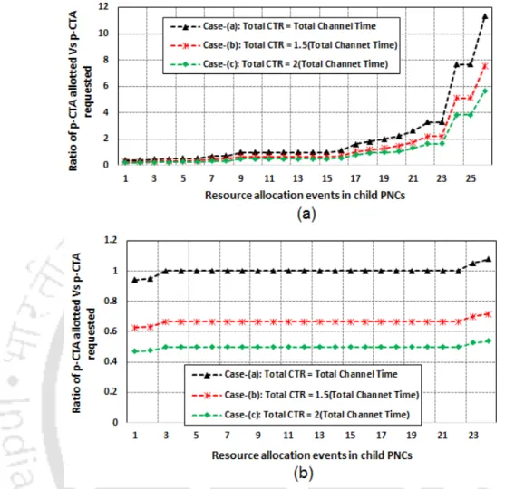
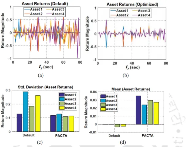
In (5.12), the parameter Xi,m indicates the ratio of the cumulative p-CTA allocated and requested at each slave piconet. 5.8, it can be observed that the CTmIsoi component of funds is positively correlated with CTmU noisedi. Therefore, since CTmU is instead associated with inefficient p-CTA allocation and higher volatility, we conclude that assets with higher CTmIsoi values will worsen the portfolio volatility scenario.
Conclusions
Since the MLC architecture-based blocking mitigation solutions use a fixed amount of redundant infrastructure (for example, in terms of the standby network or backup links) to achieve blocking tolerance, they cannot adapt to changing blocking conditions. Therefore, a large portion of network capacity and other vital network resources usually remain unused and thus wasted. Thus, an efficient channel time distribution mechanism is achieved that allows better utilization of the network resources.
Further Scope of Work
The IEEE 802.15.3c MAC standard for mmWave systems supports both parent-child (p/c) and parent-neighbor (p/n) forms of SOP hierarchies. However, in both these structures a common approach is followed by the parent PNC to distribute its channel time resources. A.2(a), Case-(b) and (c) represent the two different scenarios of adding a new piconet (C3) at different levels in the SOP hierarchy.
Markowitz’s Portfolio Allocation Model
MacCartney et al., "Millimeter Wave Wireless Communications: New Results for Rural Connectivity," in proc. Rappaport, "Omnidirectional path loss models in New York City at 28 GHz and 73 GHz," in proc. Rappaport, "73 GHz millimeter wave propagation measurements for outdoor urban mobile and backhaul communications in New York City," in proc.
![Figure 3.3: Relationship between the state-transition probabilities of the statistical model in [14] and the derived bi-state channel model for the self-backhaul links.](https://thumb-ap.123doks.com/thumbv2/azpdfnet/7616270.201177/70.892.101.765.169.664/figure-relationship-transition-probabilities-statistical-derived-channel-backhaul.webp)