Civil Engineering Forum Volume XX/1 - September 2011
1219 STABILITY OF UNDERWATER STRUCTURE UNDER WAVE ATTACK
C. Paotonan
Engineering Faculty, Hasanuddin University, Makassar, INDONESIA E-mail: [email protected]
D. B. P. Allo
Civil Engineering Department, Cenderawasih University, Jayapura, INDONESIA E-mail: [email protected]
ABSTRACT
Geotube is, among others, a type of coastal structure that is increasingly accepted for coastal protection especially underwater breakwater. Besides its relatively low cost, it has other advantages such as flexibility, ease of construction and the fact that it can be filled with local sand material. Similar to all other coastal structures, it should also be stable under wave attack. A simple theoretical approach based on linear wave was adopted to estimate the stability of such structure. The theoretical solution was then compared with an experimental study. The experimental study was conducted at the Hydraulics and Hydrology Laboratory of Universitas Gadjah Mada. However, instead of a real geotube, PVC pipe was used where the weight of the PVC was varied by adjusting the volume of sand in the pipe. The result indicated that the agreement between the theoretical solution and the experiment was encouraging. The analytical solution may be utilized to predict underwater pipe stability under wave attack with certain degree of accuracy.
Keywords: Geotube, initial movement, submerged structure.
INTRODUCTION
Geotube is a type of coastal structure which can be used as coastal protection. Basically geotube is a geosyntetic type of material which is stitched to form a tube when filled with sand or cement material.
Geotube can be used as groin, jetty, or even breakwater as long as the material is strong enough against debris or sunlight. The advantage of geotube is its flexibility size as normally the size of geotextile is almost unlimited when stitched to one another. It is also lightweight which makes transportation easy. There are other economic advantages that make the structure increasingly acceptable.
When used as a breakwater it has to be strong enough to withstand wave force and current (Pilarczyk, 1998, 2000). For this reason, the paper discusses the stability of geotube underwater breakwater.
Researches related to geotube as a coastal structure have been carried out by many such as Shin E.C, and Oh Y.I. (2007) who studied the stability of Geotube based on two-dimensional physical model. Paotonan et al (2011) analyzed the geotube stability under sinusoidal wave attack.
Civ
il Engineering
otube can a exico to prot
El Dorado R ached break e protected donesia, geo
ations, for rtamaya reso
e cross sect quired, thoug
ed with sand geotube wil
is not full umed to be s nearly roun
HEORETICA e forces act
rtia force, oyancy force
Gravitationa e weight of itten as:
here ρs is ge
r meter len avitational ac are kg/m3, m oss section is weight of g
e buoyancy reduced we
ernatively, fo
e net force o
also be fou tect the erod Royale Reso kwater. The by the st otubes wer example a ort area near tion of geotu gh it is most
d. On the ot ll be close to l. In this pa fully filled w nd.
AL APPROA ting on a ge lift force e that is desc
al force f the structu
eotube speci ngth of geo cceleration. m3/m, and m
s round with geotube is
force (FB)
eight in the w
or cylindrica
on geotube i 2 ded beach. T ort, Mexico e length of tructure is re installed at Lombang
Indramayu, ube may be tly rounded ther hand, th o ellipse wh aper, the ge with sand an
ACH eotube are , gravitatio cribed below
ure in air (W
ific mass, Vs
otube, and The unit of m/s2 respectiv
h diameter D
that is resp water can be
al geotube it
n the water
atan coast, The geotube
is a typical the coastal
4 km. In in many g coast of West Java. e shaped as
when fully he shape of en the sand eotube was nd the shape
drag force, onal force, w.
ponsible for written as:
(3)
The lif equatio
Where m/s, an coeffic and Re linear w
geotub wave propa d be differen m of the geot m of geotube The flow ed to follow ue to such di (lift force) ac
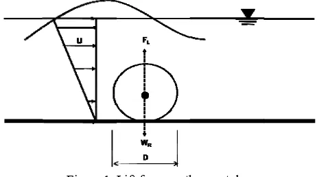
Figure 1. ft force was on
e u is velocit nd CL is a l
cient on cyli eid 1963). In wave is simp
Where
Volume X
agates above nt velocities tube. In fact e may be reg above the w the linear w
ifferential flo cting on the g
Lift force on th given by De
ty at the top lift force co
indrical bod n shallow w ply
e hs is the de
wave amplitu Equation 7
high.
XX/1 - Septem
e the geotub from the top t, the velocit garded as zer geotube m wave theory
ow, there is geotube.
he geo tube ean (1992) a
p of the stru efficient. Li dy is 4.493 ( water, velocit
epth at the to
(Figure vertical
as in this
(6)
Civ
il Engineering
Drag force e drag force
here CD is d m 1 to appr ulegan Carp uation 10, d d geotube dia
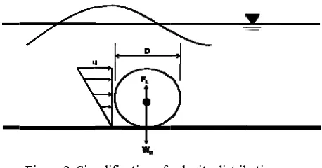
r the case tribution ca gure 2.
Figure 2. Sim
Figure 2, di r simplificati erefore, stru n equation 1
Geotube init hen an obje ter, there a otion. The f
scribed by Eq
2
takes the fo
drag force co roximately 2 penter (Dean drag force i
ameter.
of submerg an be simpli
mplification of v submerged g istribution o ion, average ucture is loc 10 can be wr
tial motion ect (geotube are two pos first is due quation 13.
oefficient, w 2.2 and is a and Dalrym is function
ged geotub ified and dr
velocity distrib geotube of velocity in
e velocity is cated in sha ritten as:
) is submer sible modes e to vertica
s
which varies function of mple, 1986).
of velocity
e, velocity rawn as in
bution on
n triangular. considered. allow water
(11)
In this total fo than th is due horizon Equati
The co the fri bottom little a sand). the bo corrod of f w betwee result.
or
Since t the sec wave h
ntal forces on 14.
oefficient f i ction factor m. The fricti
s 0.0002 (on In this exper ottom of th ded steel. Th will be varie
en the exper Equation 14
the drag for cond mode height requi e written as:
n-dimensiona written as:
Volume X
geotube is n buoyancy an the structure mbined forc (drag for
is introduced r between th ion coefficie n steel) to as riment, the m he flume, w
erefore, in th ed to find
imental data 4, can be sim
ce coincides is more lik ired to dest
al parameter
L
XX/1 - Septem
not stable w nd lift force i e. The secon ces of verti rce) as giv
d in Equatio he geotube ent f ranges s high as 0.4 model was p which was his matter th out the cor a and the the mplified as:
s with the lif kely to occ abilize the
r form, Equa
s slightly he value rrelation eoretical
(15)
(16)
ft force, ur. The geotube
(17)
ation 15
Civil Engineering Forum Volume XX/1 - September 2011
1222
Therefore, the non-dimensional parameters relevant to the initial motion of the geotube are H/D, 1
s and
D hs
Equation 16 will be used to
calculate minimum wave height needed for the structure to start moving.
E.Physical Model Simulation
The experimental study was conducted in a regular wave flume of 30 cm wide. PVC pipes of different sizes that were closed at both ends were used as geotube models. In order to vary the weight of the model and hence its overall density, the pipes were filled with water and sand of different volumes. The diameter of the pipes was 13.02 cm (model I), 11.02 cm (model II) and 8.374 cm (Model III). The models are shown in Figure 3.
Figure 3. Model of geotubes
Each model was tested under sinusoidal waves attack. The test was initiated using small wave amplitudes and was increased at small increment to observe the initial motion of the geotube models that indicate instability. The wave heights were measured using wave probes. The geotube model during the test is shown in Figure 4.
Figure 4. Testing models in the wave flume
The models were run for all (three geotubes) models. The results, together with the analytical approach, were given in the next section.
RESULTS AND DISCUSSION
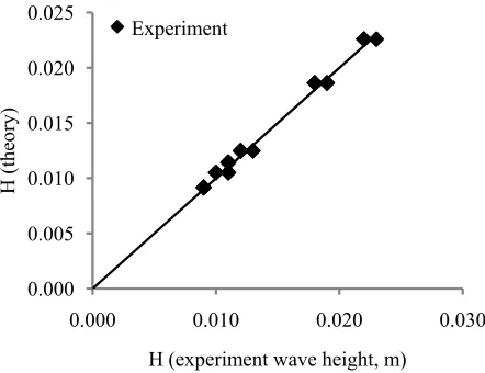
The results of the experimental work are given in Table 1 and Figure 5. It can be seen that the agreement between the theoretical and the experimental data is encouraging. However, the real friction coefficient has to be determined for better comparison. In this study, the friction coefficients was tried and the best fit was chosen. Hence, with such value of f (the best fit) only a trend comparison between the experiment and the theoretical solution can be made. The final trial indicated that f = 0.00546 produced the best fit.
Figure 5. Theoretical vs Experimental wave height required for geotube models initial motion
( f = 0.00546; CD = 2.200 and CL = 4.489)
Model
Model I Model II Model III
Model III Model II
Model I
0.000 0.005 0.010 0.015 0.020 0.025
0.000 0.010 0.020 0.030
H (t
he
o
ry
)
H (experiment wave height, m) Data
Civil Engineering Forum Volume XX/1 - September 2011
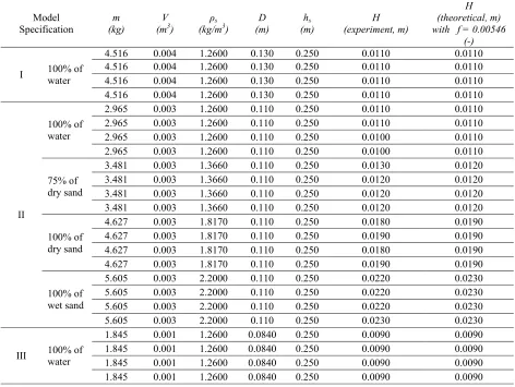
1223 Table 1. Experimental and theoretical minimum wave height for geotubes model stabilization
Model Specification
m (kg)
V (m3)
ρs
(kg/m3)
D (m)
hs
(m)
H (experiment, m)
H (theoretical, m) with f = 0.00546
(-)
I 100% of water
4.516 0.004 1.2600 0.130 0.250 0.0110 0.0110
4.516 0.004 1.2600 0.130 0.250 0.0110 0.0110
4.516 0.004 1.2600 0.130 0.250 0.0110 0.0110
4.516 0.004 1.2600 0.130 0.250 0.0110 0.0110
II
100% of water
2.965 0.003 1.2600 0.110 0.250 0.0110 0.0110
2.965 0.003 1.2600 0.110 0.250 0.0110 0.0110
2.965 0.003 1.2600 0.110 0.250 0.0100 0.0110
2.965 0.003 1.2600 0.110 0.250 0.0100 0.0110
75% of dry sand
3.481 0.003 1.3660 0.110 0.250 0.0130 0.0120
3.481 0.003 1.3660 0.110 0.250 0.0120 0.0120
3.481 0.003 1.3660 0.110 0.250 0.0120 0.0120
3.481 0.003 1.3660 0.110 0.250 0.0120 0.0120
100% of dry sand
4.627 0.003 1.8170 0.110 0.250 0.0180 0.0190
4.627 0.003 1.8170 0.110 0.250 0.0190 0.0190
4.627 0.003 1.8170 0.110 0.250 0.0180 0.0190
4.627 0.003 1.8170 0.110 0.250 0.0190 0.0190
100% of wet sand
5.605 0.003 2.2000 0.110 0.250 0.0220 0.0230
5.605 0.003 2.2000 0.110 0.250 0.0220 0.0230
5.605 0.003 2.2000 0.110 0.250 0.0220 0.0230
5.605 0.003 2.2000 0.110 0.250 0.0230 0.0230
III 100% of water
1.845 0.001 1.2600 0.0840 0.250 0.0090 0.0090 1.845 0.001 1.2600 0.0840 0.250 0.0090 0.0090 1.845 0.001 1.2600 0.0840 0.250 0.0090 0.0090 1.845 0.001 1.2600 0.0840 0.250 0.0090 0.0090
Figure 5 shows that the trend of the experimental wave heights that agree with the theoretical solution. Using regression technique a fitting curve as in Figure 5 indicates a slope of unity, showing the best fit of the f value and indicates the agreement of the experimental and theoretical data trend. The parameter for the best agreement was 0.00546; 2.200, and 4.493 for f, CD, and CL
respectively at the initial movement of a submerged coastal structure. In terms of non dimensional parameter, the results of the experiment may be compared with the theoretical solution in Figure 6 and Figure 7.
Figure 6 shows that increasing value of (ρs/ρ-1)
causes the increasing value of H/D, which means that when the value of specific gravity of structure increases, the wave height required to stir the structure is greater. If the geotube specific gravity and the water depth are constant, the
effect of water depth and geotube diameter ratio on H/D can be obtained. The influence of hs/D on
H/D for a constant ρs/ρ can be seen in Figure 7.
Figure 6. Relationship between ρs/ρ-1 and H/D
0.05 0.08 0.11 0.14 0.17 0.20 0.23
0.200 0.700 1.200
H/D
ρs/ρ-1
Civil Engineering Forum Volume XX/1 - September 2011
1224
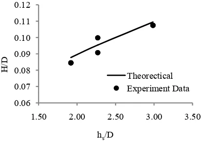
Figure 7. Relationship between hs/D and H/D
Again, Figure 7 shows that the trend between the measurements in the laboratory and the theoretical calculation is similar. The increasing value of hs/D causes the increasing H/D value.
Using Equation16 the combination of non dimensional parameter that affects H/D is
D hs
s
1
where the correlation is indicated in
Figure 8. The line and scatter point in the Figure are theoretical line and data experiment, respectively.
Figure 8. The combinative effects of ρs/ρ-1 and hs/D
on H/D
Figure 8 shows the increasing value of (ρs/ρ
-1)(hs/D) causes the increasing values of H/D.
Theoretical value of H/D on Figures 5 to 8, were calculated by assuming that f, CD, and CL values
were 0.00546; 2.200 and 4.498 respectively. Using Equation 17, H/D values as a function of geotube specific gravity and ratio of depth water to geotube diameter can be calculated where the result is presented in Figure 9.
Figure 9. Geotube Initial movement graph
Using Figure 9, the initial movement of submerged structure can be predicted. A situation that is represented by a point located above of the curve of Figure 9 is unstable and vice versa. Suppose a geotube under wave attack of (ρs/ρ
-1)(hs/D) = 5.0 and H/D = 0.4 it indicates that the
structure is theoretically unstable while a geotube of (ρs/ρ-1)(hs/D) = 5.0 and H/D = 0.1 is
theoretically settled.
CONCLUSIONS
Based on the explanation above, it can be concluded into some points below. Firstly, the stability of a submerged structure is influenced by wave parameters (height and water depth) and structure parameters; those are the specific gravity and the diameter of structure, D. Secondly, the wave height trend which is able to move the structure obtained from experimental data and calculation with Equation 15 are equal. Thirdly, as the value of structure specific gravity increases, the wave height which is needed to move the structure is increasing too. Or in other words as the specific gravity of structure increases, the structure is more stable as well. Fourthly, if the value of water depth and structure diameter is getting greater, the effect on wave height and structure diameter ratio is getting greater and follows the logarithmic trend. Combination of non-dimensional parameter which influences the ratio of wave height value and structure diameter is (ρs/ρ-1)(hs/D). As the
value of (ρs/ρ-1)(hs/D) increases, the value of H/D
increases too. The initial movement of geotube can be predicted by using Equation 17 or Figure 9.
moving
unmoving
0.06 0.07 0.08 0.09 0.10 0.11 0.12
1.50 2.00 2.50 3.00 3.50
H/
D
hs/D
Theorectical Experiment Data
0.00 0.05 0.10 0.15 0.20 0.25
0.00 1.00 2.00 3.00
H/
D
(ρs/ρ-1)(hs/D) Theoretical Experiment Data
0.00 0.10 0.20 0.30 0.40 0.50 0.60
0.00 5.00 10.00 15.00 20.00
H/
D
Civil Engineering Forum Volume XX/1 - September 2011
1225 ACKNOWLEDGMENTS
The authors would like to thank Directorate General of Higher Education (DIKTI) and Hasanuddin University for financial support to do the research. Invaluable comments, suggestions and corrections by Prof. R. Triatmadja especially with respect to the stability of geotube of the original paper is highly appreciated. The authors also express their sincere gratitude to the Head of the Centre of Engineering Science Studies and the Head of Hydraulics and Hydrology Laboratory, Universitas Gadjah Mada, for the facilities to support this research.
REFERENCES
Dean, R.G. and Dalrymple, R.A. (1993). Water Wave Mechanic for Engineer and Scientist. World Scientific Publishing. Singapore. Koerner, G.R., Koerner, R.M. (2006). Geotextile
tube assessment using a hanging bag test. Geotextiles and Geomembranes 24 (2), 129–137.
Muthukumaran, A.E., Ilamparuthi, K. (2006). Laboratory studies on geotextile filters as used in geotextile tube dewatering. Geotextiles and Geomembranes 24 (4), 210–219.
Oh, Y.I., and Shin, E,C. (2006). Using submerged geotextile tubes in the protection of the E. Korean shore. Coastal Engineering 53 (2006) 879–895, accepted 1 June 2006, www.Sciencedirect.com.
Paotonan. C, Nur Yuwono, Radianta Triatmadja, and Bambang Triatmodjo (2011). Theoretical Approach of Geotextile Tube Stability as a Submerged Coastal Structure. Proceeding of International Seminar on Water Related Risk Management, Jakarta. Pilarczyk, K. W. (1995). Novel systems in coastal
engineering: Geotextile systems and other methods, an overview. HYDRO pil Report, Road and Hydraulic Engineering Division of the Rijkswaterstaat, Delft, The Netherlands.
Pilarczyk, K.W. (1999). Geosynhtetics and Geosystem in Hydraulic and Coastal engineering, A. A Balkema, Rotterdam ([email protected]; www.balkema.nl). Pilarczyk, K.W. (1998). Stability criteria for
geosystems—an overview. Proceedings of the Sixth International Conference on Geosynthetics, Atlanta, USA, vol. 2. pp. 1165–1172.
Pilarczyk, K.W. (2000). Geosynthetics and Geosystems in Hydraulic and Coastal Engineering. A.A. Balkema, Rotterdam.
Shin E.C. and Oh Y.I. (2007). Coastal erosion prevention by geotextile tube technology. Geotextiles and Geomembranes 25 (2007) 264-277.
Civil Engineering Forum Volume XX/1 - September 2011
1226