DENSE MULTIPLE STEREO MATCHING OF HIGHLY OVERLAPPING UAV
IMAGERY
Norbert Haala*, Mathias Rothermel
Institute for Photogrammetry, University of Stuttgart [firstname.lastname]@ifp.uni-stuttgart.de
Commission I, WG I/V
KEY WORDS: Platforms, Point Cloud, Matching, DEM/DTM, Surface, High resolution, Three-dimensional, Performance
ABSTRACT:
UAVs are becoming standard platforms for applications aiming at photogrammetric data capture. Since these systems can be completely built-up at very reasonable prices, their use can be very cost effective. This is especially true while aiming at large scale aerial mapping of areas at limited extent. In principle, the photogrammetric evaluation of UAV-based imagery is feasible by of-the-shelf commercial software products. Thus, standard steps like aerial triangulation, the generation of Digital Surface Models and ortho image computation can be performed effectively. However, this processing pipeline can be hindered due to the limited quality of UAV data. This is especially true if low-cost sensor components are applied. To overcome potential problems in AAT, UAV imagery is frequently captured at considerable overlaps. As it will be discussed in the paper, such highly overlapping image blocks are not only beneficial during georeferencing, but are especially advantageous while aiming at a dense and accurate image based 3D surface reconstruction.
* Corresponding author.
1. INTRODUCTION
UAVs are establishing as serious alternative for traditional photogrammetric data capture. Since these systems can be completely built-up at very reasonable prices, photogrammetric data collection can be very cost effective. This is especially true while aiming at large scale aerial mapping of areas at limited extent. In principle, the photogrammetric evaluation of UAV-based imagery is feasible by of-the-shelf commercial software products. Thus, standard steps like aerial triangulation, the generation of Digital Surface Models and ortho image computation can be performed effectively. However, this processing pipeline can be hindered due to the limited quality of UAV data. This is especially true if low-cost sensor components are applied.
Standard aerial image collection is usually combined with differential GNSS measurement to provide the camera stations at centimeter accuracies. Furthermore, digital airborne cameras are frequently mounted to stabilized platforms, which guarantees camera views close to nadir. Finally, integrated GNSS/inertial systems can be used for direct georeferencing. These sensor components are beneficial for automatic block configuration and allow an aerial triangulation at considerable accuracies. In contrast, the evaluation of UAV imagery frequently rests on low-cost navigation grade GNSS measurements, which substantially limits the accuracy of the measured camera station. Automatic aerial triangulation (AAT) is additionally hindered by the high flight dynamics of UAV platforms. These can easily result in significant deviations of the respective images from nadir view. Furthermore, the use of consumer cameras for UAV image collection results in small footprints if compared to digital airborne cameras. In combination with the high flight dynamics this causes considerable deviations in mutual image overlaps. As a
consequence, standard assumptions and implications used during standard AAT do not hold true anymore.
Due to these reasons, alternative structure-and-motion algorithms are additionally integrated to guarantee successful block configuration of UAV imagery. Within this context, an increased redundancy of image measurements is used to overcome potential problems in AAT. Thus, UAV imagery is frequently captured at considerable overlaps. As it will be discussed in the paper, such highly overlapping image blocks are not only beneficial during georeferencing, but are especially advantageous while aiming at a dense and accurate image based 3D surface reconstruction. Within our investigations dense 3D point clouds are generated using the Semi-Global Matching (SGM) stereo method. The potential of the SGM algorithm was already demonstrated for different applications and data sets, including aerial images, satellite data or video sequences. This was our motivation to implement and use SGM for dense image matching from multiple overlapping UAV imagery. Since this approach aims at a pixel-wise matching, geometric surface reconstruction is feasible at a resolution similar to the available ground sapling distance of the captured imagery. For our investigations, data from flight campaigns with a low-cost fixed-wing UAV, equipped with a consumer grade digital camera and a low-cost GPS are used. The low cruising speed of the UAV easily allows an image acquisition at large overlaps in flight direction. Additionally, rather short distances between the respective flight lines were selected. This results in overlaps, which allow for a typical visibility of each object point in more than 20 images. This is a considerable increase in redundancy if compared to standard stereo capture by two image rays as available from traditional photogrammetric blocks.
Within our implementation, this redundancy is utilized for image based surface reconstruction by linking corresponding pixels from multiple images. For this purpose, a base image is matched against the surrounding images. This provides International Archives of the Photogrammetry, Remote Sensing and Spatial Information Sciences, Volume XXXIX-B1, 2012
corresponding measurements, which consist of pixel coordinates of the base image and the multiple pixel coordinates in the respective match images. As demonstrated within the paper, the following point determination from multiple image rays can efficiently eliminate potential mismatches by suitable filter processes. Thus, the accuracy and reliability of image based 3D point cloud generation is increased considerably. By these means high quality surface reconstruction is feasible even from imagery of limited quality as available from UAV-borne consumer grade digital cameras. Our investigations will be verified by for data sets captured at a test site already used for evaluation of digital photogrammetric camera systems. Thus, a comparison of our dense multiple stereo matching of highly overlapping UAV imagery to standard photogrammetric data collection by digital airborne cameras is feasible.
2. UAV-PLATFORM
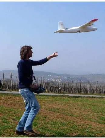
Our airborne platform was provided by a low-cost fixed-wing UAV developed by the Institute of Flight Mechanics and Control, University of Stuttgart. The Elapor foam construction has a wingspan of 1.4 meters and a take-off weight around 1.3 kg. The airframe, motors, actuators and power supply are commercial of the shelf components whereas the on-board computing system is a custom design, based on a field-programmable-gate-array (FPGA) (Weimer et al., 2010). A custom IP core on the FPGA is serving as a flexible I/O link to collect and pre-filter sensor data, drive servo actuators and motor controllers, link to the communications controller and trigger the camera. The UAV has a cruising speed of about 20 m/s and is able to fly up to 20 minutes on low wind conditions. Therefore it can cover a flight distance of roughly 20 km after subtracting some reserves for climbing and landing.
Figure 1: Used fixed-wing UAV platform in flight.
The UAV system enables fully automatic flights along commanded waypoints including automatic take-off and landing. During flights it can be monitored and commanded by a PC based ground station which is connected via RF link. The self-developed ground station software manages waypoint lists and monitors the airplane during flight, although the autonomous operation is not affected by signal loss. The autopilot can be overruled by a common RC link which allows a backup pilot taking over in emergency situations or e.g. for
difficult landings. Sensors on board are 3-axis gyros, accelerometers, 3-axis magnetometer, barometer and a single channel GPS receiver. During the flight, the information of the sensor readings is used to estimate flight path angles, velocity and position of the airplane. In order to improve the accuracy of GPS-aided aerial triangulation, a u-blox LEA 6T GPS receiver was used. The hardware is still small size and low weight, but additionally includes carrier phase with half-cycle ambiguity resolved in the UBX-RXM-RAW message. By these means, the horizontal position precision of 2.5m for the navigation solution from GPS L1 frequency C/A code can be improved to decimeter level during post-processing.
Figure 2: Used consumer camera mounted on UAV belly (left) and fixed lens element (right).
As shown in Figure 2 (left), the camera for the aerial image collection is mounted to the belly of the UAV. The camera is triggered from the on-board computer via the camera USB interface in combination with a CHDK firmware. The used Canon IXUS 100 IS is a consumer camera at a nominal focal length of 5.90mm. It features a 1/2.3” CCD which corresponds to a CCD sensor size of 4.62x6.16mm with 1.54x1.54m² pixel size each, which provides images of 3kx4k pixel.
The accuracy achieved during photogrammetric processing of UAV imagery is frequently limited by the geometric stability of the respective cameras. Of course, the applied consumer grade cameras can be calibrated before the photogrammetric flight. However, due the camera instability this a priori lab calibration only may serve as a first approximation of the real camera geometry during the evaluation of the flight. Even more important, the stability of camera calibration can be considerably limited due to image stabilization (IS) techniques. Image stabilization, which is frequently integrated in consumer grade cameras automatically detects and corrects camera movement during image acquisition. Within the Canon IXUS the camera shake is measured by two piezoelectric gyroscopic sensors. This information is then used to compute drive signals for the electromagnets, which move the IS floating lens element parallel to the image plane. For standard consumer grade applications, the movement of the IS lens group counteracts image shake and maintains a stable picture. However, in an UAV environment the stability of camera calibration as a prerequisite for precise photogrammetric data capture is lost. To avoid movement of the IS lens group due the flight dynamics the moving lens was fixed. As depicted in Figure 2 (right) the lens system was demounted and fixed with adhesive.
3. IMAGE ORIENTATION
For a considerable number of applications, data collection by fixed-wing UAVs is still based on classical image strips. Usually, the resulting image configuration allows standard assumptions and implications, which can be used for block generation during automated aerial triangulation (AAT). However, these assumptions do not hold true anymore if UAV platforms are used. In such scenarios, deviations of 5-10° from International Archives of the Photogrammetry, Remote Sensing and Spatial Information Sciences, Volume XXXIX-B1, 2012
nadir view can easily occur due the higher flight dynamics in UAV environments. In contrast to conventional airborne camera systems, these movements are not eliminated by a stabilization of the camera platform. In combination with the relatively small image footprint this results in considerable deviations in mutual image overlaps. This will frequently aggravate the successful block configuration and thus hinder processing of UAV imagery by commercial software tools. However, since UAV image blocks are frequently captured with high overlap potential problems during photogrammetric evaluation can be overcome from this increased redundancy.
3.1 Flight configurations
The flight configuration used in our investigations is depicted in Figure 3. The area was covered with five flight lines with a length of 1.1 km. At the assumed cruising speed of 20m/s, the selected image rate of one shot each 1.5 seconds provided base-length of 30m and an overlap of 75% in flight direction. The distance between neighbouring flight lines of 50m resulted in a nominal overlap of 70% across flight direction. In order to provide a stable block configuration, two flight lines cross block were additionally captured, which resulted in an overall number of 202 images. In Figure 3 the planned flight lines are depicted in yellow, the captured camera stations are represented by red circles and the 32 signalized GCPs are represented by blue crosses.
Figure 3: Test-site Vaihingen/Enz, with planned flight lines, camera stations from GPS measurement, and signalized points. As it will be also discussed in section 4, this configuration provides a considerable image overlap, which can efficiently support both automated aerial triangulation and dense surface reconstruction.
3.2 Automated Aerial Triangulation
Automatic aerial triangulation (AAT) requires suitable tools on image matching for the generation of tie points. This task is solved for standard aerial image blocks by commercial software systems for more than a decade (Tang et.al., 1997). A priori information is usually integrated during point transfer to define suitable search areas between neighboring images. The required information on mutual image overlap is available from the so-called block configuration. Frequently, this is generated from GPS measurements of the camera stations while assuming nadir views. While this is sufficient for photogrammetric flights with large format cameras, block configuration is much more complex for UAV imagery. There high flight dynamics in combination with the relatively small image footprint considerable aggravate the a priori determination of mutual image overlaps. Thus, we use a so-called Structure and Motion (SaM) approach to alternatively reconstruct image connectivity.
Originally, these tools were developed for the reconstruction of large, unordered, highly redundant, and irregularly sampled photo collections. An example, is the software system “Bundler” developed during the Photo Tourism Project of the University of Washington (Snavely et. al. 2007), which was successfully used for bundle block adjustment of UAV imagery (Kichgäßner et al., 2010). Meanwhile, our processing of large UAV image datasets is based on a SaM implementation presented in (Abdel-Wahab et.al. 2011), which uses an approach similar to (Farenzena et al., 09).
The basic idea is to reduce the reconstruction problem by separating the complete image block to smaller and better conditioned sub-groups of images which can be optimized effectively. For this purpose, the dataset is split into patches of a few stable images which are then merged within a global bundle adjustment after an accurate and robust reconstruction for each patch. First, feature matching is realized using the SIFT operator (Lowe, 2004). After the extracted keypoints are tracked over all images, the results are stored in a visibility matrix, which represents the appearance of points in the images. To increase the reliability of the remaining tie points, all a points visible in less than 3 images are eliminated in a first filter step. In order keep only points with the highest connectivity, for each image the keypoints are sorted in descending order according to their number of projections in other images. Then, the point with the greatest number of projections is visited, followed by identification and rejection of all nearest neighbor points with a distance less than a certain threshold. After an incremental patchwise reconstruction, a global bundle adjustment is performed which provides orientations and 3D feature point coordinates of the entire model.
Figure 4: Tie points and cameras station as reconstructed from implemented SaM approach.
Figure 4 depicts the results of the pipeline including the oriented camera stations and the used tie points. As it is visible, the tie points are distributed very well over the complete test area, which provides stable block geometry. Since the orientation parameters from the implemented SaM approach refer to a local model coordinate system, they are transformed into the reference coordinate system using the GPS measurements of the camera stations. Based on these results an evaluation with the standard AAT software package MATCH-AT (Sigle & Heuchel, 2001) is initialized. This software is then used for manual measurement of signalized points which are then used during a refined AAT. For the image block depicted in Figure 3 this resulted in a σ0 of 1.4m or 0.9pixel. The mean standard deviation at the signalized check points was 4.4cm for International Archives of the Photogrammetry, Remote Sensing and Spatial Information Sciences, Volume XXXIX-B1, 2012
the horizontal and 18.1cm for the vertical component. This is a considerable increase in accuracy performance compared to earlier investigations presented in (Haala et.al., 2011). There, remaining problems in absolute accuracy were documented, which for example resulted in systematic deviations between the elevations of tie points to a reference DSM. These problems were traced back to geometric instability of the camera geometry. However, these problems were eliminated by fixing the IS lens group of the IXUS camera as discussed in section 2. Of course the increased accuracy and reliability of AAT is advantageous for dense surface reconstruction as described in the following section.
4. DENSE SURFACE RECONSTRUCTION
Tools for DSM generation by automatic stereo image matching are available for more than two decades. However, the revival of image based 3D data collection was triggered only recently due to important hardware and software developments. One example is the success of algorithms like the Semi-Global Matching (SGM) stereo method as proposed by (Hirschmüller, 2008). This approach, used for our investigations on dense multiple stereo matching of highly overlapping UAV imagery approximates a global approach by minimizing matching costs, which are aggregated along a certain number of 1D path directions through the image. By these means, the pixel-wise SGM approach provides a dense point distribution, while the global approximation on paths enables a reasonable runtime on large imagery. The potential of the SGM algorithm was already demonstrated for different applications and data sets. This was our motivation to implement and use SGM for dense image matching, which already provided a considerable improvement compared to standard commercial tools while using standard aerial imagery (Haala, 2011). These investigations also showed the benefits of combining multiple image information during surface reconstruction and 3D point cloud generation.
Figure 5: Image overlap as captured from UAV-flight.
The required large image overlap can be provided without any problems from UAV flights due to the low cruising speed. For our test data set this is clearly demonstrated in Figure 5. As it is visible from the colour coded mutual image overlap, a single object point is depicted in up to 34 images. This is a considerable increase of redundancy compared to two image rays as available for image-based surface reconstruction from traditional photogrammetric blocks. As it will be demonstrated this increase in redundancy allows for a reliable and dense matching of the UAV imagery as collected from low-cost consumer camera.
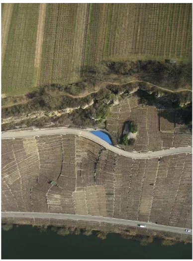
Figure 6: Exemplary UAV image.
An exemplary image of the investigated flight is depicted in Figure 6. The captured area features a terrain undulation of about 100m, thus the flying height varies between 219m above ground for the valley floor and 125m above ground for the summit area. The flying height with respect to the area marked in blue is 166m, which results in a GSD of 4.3cm. The image footprint is approximately is 128mx170m.
4.1 Stereo matching
Figure 7: Stereo and corresponding parallax image for Figure 6. The corresponding result of our SGM-based stereo matching is given in Figure 7. While the base image is depicted in Figure 6, the search image used during stereo matching partner is shown in Figure 7 (left). The stereo pair, i.e. base and search image are normalized into epipolar geometry before a so-called disparity image is computed by pixel-wise matching (Figure 7 (right)). For each pixel of the base image this disparity image defines the parallax with respect to the search image, which can then be used to compute a 3D point cloud by spatial intersection. Since the implemented SGM aims on a per-pixel disparity measurements, the resulting point density will correspond to the resolution of the available stereo image pair. However, within International Archives of the Photogrammetry, Remote Sensing and Spatial Information Sciences, Volume XXXIX-B1, 2012
the disparity image in Figure 7 (right) white areas are visible. These result from apparently wrong parallaxes of the core SGM process, which were eliminated by a simple consistency check with changed roles of base and match images during matching. Only disparity estimations consistent to this forward-backward matching are then considered as valid. As it is visible in Figure 7 (right) erroneous matches mainly occur at regions, which are potentially problematic for image matching. These are areas of low texture e.g. at streets or reflecting surfaces like the river. Furthermore, problems result from larger differences in image content of the stereo pair. Such differences e.g. occur at complex 3D shapes like vegetation or steep object surfaces at the walls and rocks.
4.2 Multiple image matching
Despite the fact that differences between forward-backward matching provide a first estimate of matching quality, an evaluation of point accuracy in 3D object space based on multiple matches is much more reliable. These multiple matches are realized by defining the central image for an area of interest as the base image, which is then matched against the surrounding images. Thus, corresponding measurements across multiple match images are related by a pixel coordinate in the base image and the corresponding pixel coordinates in the respective match images. Thus, a link between pixels in multiple images representing the same object point is established by defining a central image as the base image, which is then matched with the surrounding images
Figure 8: Amount of overlap for single image.
Depending on the respective flight and camera parameters, different configurations are feasible. For the stereo image pair in Figure 6 and Figure 7, the base-length in flight direction is 30m, which results in a nominal in-flight overlap of approximately 75% for the image footprint of 128m in flying direction. The distance between the image strips is 50m. This results in a side lap of 70%, allowing for addition matching against images from the adjacent strips.
Figure 8 shows the footprint of the exemplary image depicted in Figure 6 represented in light blue. This image is then matched against all surrounding images, where the footprints are represented in dark blue. Due to the large overlap multiple matches are feasible for each pixel in the base image. As represented by the color coded overlap up to 22 matches are feasible for the given example. As described in more detail in Haala, N. (2011), this redundancy can be used efficiently to eliminate mismatches by suitable filter processes. Furthermore,
the accuracy of image-based 3D point cloud generation is increased from these multiple measures. Matching n search images to one common base image results in 2(n+1) pixel coordinates x, which can then be used to determine the respective object point X. The corresponding measurements consist of pixel coordinates xb in the base image and the respective pixel coordinates xmiin the multiple match images. Each additional stereo model generated by mapping an additional match image against the base image will increase the number of image rays to be intersected for object point determination by one. In our implementation, the spatial intersection method described by (Hartley & Zisserman 2004) is used for a computationally efficient solution. There point triangulation is realized by solving a linear system which provides the least-squares solution for the point Xi in object space. The object point Xi is then re-projected into each image to compute the respective residual for each match. If this error exceeds a certain threshold, the corresponding observation is identified as mismatch and eliminated from further processing. After this elimination of erroneous matches the spatial intersection is repeated from the remaining matches. By these an accurate and reliable 3D point clouds can be generated.
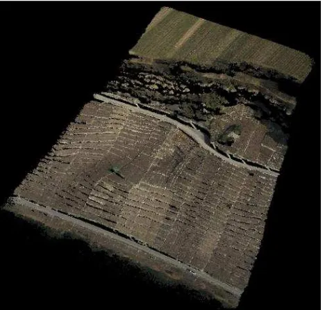
Figure 9: Point cloud generated for single match image. The 3D point cloud resulting from this spatial intersection and filtering is given in Figure 9. In principle, our matching generates a corresponding 3D point for each pixel of 3kx4k the base image in Figure 6. However, in our pipeline, a valid 3D point requires at least two successful matches. Thus areas with no valid point measurements occur as black regions in Figure 6. Approximately 8 million points are finally computed, which corresponds to a success rate of 66%. However, most mismatches occur at the river area, while for the other regions a higher success rate is reached. A rough estimate of the resulting 3D point accuracy can be realized using a planar area, which is marked by the blue polygon in Figure 6. All 3D points within that polygon were extracted and used for a least-squares estimation of an approximating plane. The residuals of the original 3D points to that plane were then used to compute their corresponding RMS error. For the marked planar area this resulted in a value of 10.2cm. This corresponds to matching accuracies of the implemented SGM algorithms of better than 0.2 pixels.
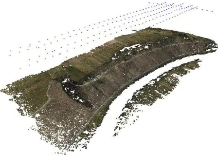
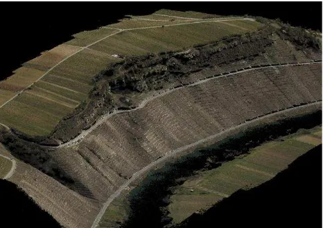
Figure 10: Point cloud for complete test area.
The point cloud depicted in Figure 9 just covers a small part of the test area as available from a single base image. Thus, similar data sets can be generated for each of the 200 images, which cover the complete test area. This result is depicted in Figure 10. In order to combine the matching results from all captured images, a simple gridding was additionally realized. There the median values of all points within a raster cell of 8cm grid width were used to compute the respective elevation of the resulting DSM. For this grid, the RMSE of the planar area marked in Figure 6 was 3.0cm.
5. OUTLOOK AND CONCLUSION
In our investigations, SGM proved to be a robust and easy-to-parameterize matching algorithm. Matching accuracies better than 0.2 pixels at high point densities were feasible even for areas with very little texture. The combination of multiple measurements in triangulation increases the accuracy of the generated 3D point clouds. Even more important, the redundancy available from the combination of stereo matches from different image pairs allows a very efficient elimination of erroneous matches and results in a considerable reliability of the 3D points at vertical accuracies in the centimetre level. Thus, even for aerial imagery of comparatively limited quality a high quality surface reconstruction is feasible. This is especially beneficial for UAV imagery, which is frequently captured using consumer grade digital camera, but can be collected at high resolutions and large overlaps.
6. REFERENCES
Abdel-Wahab, M., Wenzel, K. & Fritsch D. (2011) Reconstruction of Orientation and Geometry from large Unordered Datasets for Low Cost Applications. Proceedings LC3D Workshop, Berlin, December 2011
Farenzena, M., Fusiello, A. & Gherardi, R. (2009). Structure and motion pipeline on a hierarchical cluster tree. ICCV Workshop on 3-D Digital Imaging and Modeling, pp. 1489– 1496.
Haala, N. (2011): Multiray Photogrammetry and Dense Image Matching. Photogrammetric Week '11, Ed. D. Fritsch, Wichmann, Berlin/Offenbach, pp. 185-195.
Haala, N., Cramer, M., Weimer, F. & Trittler, M. (2011) Performance Test on UAV-based data collection Proceedings of the International Conference on Unmanned Aerial Vehicle in Geomatics (UAV-g). IAPRS, Volume XXXVIII-1/C22, Zurich, Switzerland, 2011, 6p.
Hartley, R.I. & Zisserman, A., (2004), Multiple View Geometry in Computer Vision, Cambridge University Press, Cambridge, Chap.12.
Kirchgäßner, U., Putze, U., von Schönermark, M. & Haala, N. (2010) Anforderungen an die Auswertung UAV-gestützter Fernerkundungsdaten DGPF Tagungsband 19/2010 – Dreiländertagung OVG, DGPF und SGPF pp. 597 – 605 Lowe, D. 2004: Distinctive Image Features from Scale-Invariant Keypoints In: International Journal of Computer Vision. Vol. 60, No. 2, pp. 91-110.
Sigle, M. & Heuchel, T. 2001: MATCH-AT: Recent Developments and performance, Photogrammetric Week 01, pp. 189-194.
Snavely, N., Seitz, S. & Szeliski. R. (2007) Modeling the World from Internet Photo Collections. International Journal of Computer Vision, 2007.
Tang, L., Braun, J. & Debitsch, R. (1997). Automatic Aerotriangulation - concept, realization and results. ISPRS Journal of Photogrammetry & Remote Sensing 52(1997), 122-131.