CAMERA CALIBRATION ACCURACY AT
DIFFERENT UAV FLYING HEIGHTS
Ahmad Razali Yusoff a, Mohd Farid Mohd Ariff a, Khairulnizam M. Idris a, Zulkepli Majid a, Albert K. Chong b
a
Geospatial Imaging and Information Research Group, Universiti Teknologi Malaysia, Malaysia
b Faculty of Engineering & Surveying, University of Southern Queensland, Australia
Commission II
KEYWORDS: Camera calibration, accuracy assessment, object distances, UAV flying heights
ABSTRACT:
Unmanned Aerial Vehicles (UAVs) can be used to acquire highly accurate data in deformation survey, whereby low-cost digital cameras are commonly used in the UAV mapping. Thus, camera calibration is considered important in obtaining high-accuracy UAV mapping using low-cost digital cameras. The main focus of this study was to calibrate the UAV camera at different camera distances and check the measurement accuracy. The scope of this study included camera calibration in the laboratory and on the field, and the UAV image mapping accuracy assessment used calibration parameters of different camera distances. The camera distances used for the image calibration acquisition and mapping accuracy assessment were 1.5 metres in the laboratory, and 15 and 25 metres on the field using a Sony NEX6 digital camera. A large calibration field and a portable calibration frame were used as the tools for the camera calibration and for checking the accuracy of the measurement at different camera distances. Bundle adjustment concept was applied in Australis software to perform the camera calibration and accuracy assessment. The results showed that the camera distance at 25 metres is the optimum object distance as this is the best accuracy obtained from the laboratory as well as outdoor mapping. In conclusion, the camera calibration at several camera distances should be applied to acquire better accuracy in mapping and the best camera parameter for the UAV image mapping should be selected for highly accurate mapping measurement.
1. INTRODUCTION
Unmanned Aerial Vehicle (UAV) photogrammetry is different from close-range photogrammetry in their distance to the object (Kerle et al., 2008). According to Eisenbei (2009), UAVs can be used as a new photogrammetric measurement tool.
The UAV photogrammetry growth depends very much on the general development of science and technology. In the last decade, research on UAVs has increased a lot in terms of the system, sensor integration, and data processing. Moreover, UAVs are gradually being applied in different scientific disciplines such as robotics, computer vision, and geomatics (Sauerbier et al., 2011).
Camera calibration is an important process in photogrammetry. It is the initial step in many machine visions and photogrammetric applications (Weng et al., 1992). Accurate camera calibration and orientation procedures are necessary for the extraction of precise and reliable three-dimensional (3D) metric information from images (Romandino & Fraser, 2006), with lens distortion being one of the major factors in camera calibration (Pan & Zhu, 2010).
A camera mounted on a UAV is able to acquire high-accuracy mapping measurement such as in deformation surveys and, in most cases, low-cost digital cameras are used for UAV mapping. Hence, camera calibration is considered important and needs to be studied to obtain highly accurate UAV mapping measurement using low-cost cameras. Lichti and Qi (2012) states that the accuracy of the calibration parameters for long camera distances can be improved in UAV mapping. There are many camera calibration techniques that have been developed in the last several years but only a few involve images that are acquired using UAVs (Pérez et al., 2011).
The camera calibration process often uses close-range calibration in laboratory condition to acquire the camera parameters as the prerequisite for the mapping process in an image mapping software. There are many recent studies on calibration techniques that have been done for short object distance such as by Sauerbier et al. (2011), Chiang et al. (2012), Tahar (2012), Deng and Li (2015), Jimenez and Agudelo (2015), and Zhou and Liu (2015). On the other hand, research on camera calibration for long object distance has also been done by Mohamed and Klaus-Peter (1999), Liu et al. (2011), Pérez et al. (2011), Rehak et al. (2013), and Skaloud et al. (2014). These researches focused on long object distance calibration only and compared it to the laboratory condition. Moreover, the accuracy of the UAV mapping measurement using different camera calibration parameters was assessed to compare a single camera parameter from the laboratory camera calibration.
Thus, this study explores and extends the calibration of non- metric cameras to several distances and the focus is more on the accuracy of the measurement between calibration parameters at three different UAV flying heights.
1.1 UAV Camera Error Sources
There are three types of errors that can be distinguished and used to characterize the behaviour of instruments such as UAV cameras, namely random errors, systematic errors, and gross errors (Pfeifer et al., 2013).
Object
minimized. The method of averaging the measurements instead of using the original measurement values performed by Pfeifer et al. (2013) can be applied in the scene model to obtain better precision results. The precision is improved by increasing the number of measurements either spatially or temporally in the averaging process. However, the averaging step does not necessarily lead to more accurate values, especially because of the existence of systematic errors.
A systematic error may stay constant during the repetition of an experiment, or it may vary slowly, for instance, because of the temperature of the chip. However, those errors can also be modelled. Systematic errors can either be calibrated or reduced by following special data capturing procedures (Chow & Lichti, 2013). The systematic errors described below are camera internal errors, errors related to the operation of the camera, or errors related to the scene structure.
i. Lens distortion: camera internal error modelled with physical parameters.
ii.Range finder offset, range periodic error, and signal propagation delay: camera internal errors modelled with physical parameters.
iii.Range error due to the coordinate position in the sensor and range errors related to the recorded amplitude: camera internal errors modelled empirically.
iv.Internal scatters: camera internal error modelled empirically and physically.
v.Fixed pattern noise: camera internal error, not modelled. vi.Camera warm-up errors and temperature that could affect the measurement: related to the operation of the camera and is quantified.
vii.Scene multi-path errors: related to the scene structure, quantified by some experiments.
Lastly, gross error, or also called blunder error, is defined as errors which do not fit into the measurement process at all.
2. METHODOLOGY
The methodology of this study involved a lot of research work. Therefore, the methodology needs to be clearly laid out to ensure the research objectives were being fulfilled. The methodology is divided into six phases to facilitate the research work.
The phases are as follows:
Phase I : Development of the calibration and accuracy assessment platform
Phase II : Setup of the calibration and accuracy assessment platform
Phase III : Implementation of camera calibration and accuracy assessment
Phase IV : Data processing Phase VI : Data analysis
2.1 Development of The Calibration and Accuracy Assessment Platform
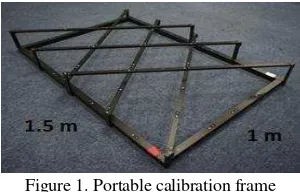
The calibration platform developed for this experiment was a portable camera calibration frame used at 1.5-metre object distance and has the dimension of 1.5 metre × 1 metre as shown in Figure 1. The target markers used in the calibration frame were retro-target points of different heights, with the diameter of the target point being 5 millimetres.
Figure 1. Portable calibration frame
Meanwhile, the camera calibration for 15 and 25 metres of object distance was done using a special black-and-white plain wooden target. The plain wood was stable to use on the ground and its position could be maintained by using long nails. The white circular target was placed on the centre of the black plain wooden target where the size of the circular target was made based on calculation.
The calculation was needed because the detection of the targets by Australis software used the automatic detection mode for this research. This automatic detection mode will detect the centre of the targets accurately and is suitable for minimizing errors in the calibration process. The size of the white circular target must be 10 pixels on the ground as recommended by Shortis et al. (1994), Ahn et al. (1999), and Fraser and Shortis (1995).
The calculation to obtain the size of 10 pixels for the white circles on the ground is presented below based on the size of one pixel of the Sony NEX6 camera.
Pixel size = camera format size / number of pixels through Photomodeler software’s pixel calculation. Once the size of one pixel was known, the calibration target sizes needed to be identified according to the object distances of 1.5, 15, and 25 metres. The formula and calculation for the target size has been included in calculation (2) and Table 1, respectively. The target size calculation is just an approximation of the minimum target size with respect to the object distance.
f/h = focal length/flying height = length : flying height (2)
Table 1. White circular target calculation
Camera distance Lines Distance (mm)
1.5 m
A31-A32 1513.2291 A17-A32 957.4346 A31-A49 960.266 15 m
25 m
BD 8973.7290
DF 8511.2331
OF 21254.865
Table 2. Final size of the white circular targets Table 3. Control measurement Camera distance White circular target size (mm)
1.5 m 5
15 m 35
25 m 60
After the diameter of all the white circular targets were known through the calculation, the black-and-white plain wooden target was made. The dimension of the plain wood was 40 cm × 40 cm to fit all the white circular targets. From the target test using Australis software, all white circular targets were set according to their particular camera distance for 15 and 25 metres; therefore, the target could be detected using the automated mode. Figure 2 shows the design of the black-and- white plain wooden calibration target used for the long-range camera calibration and accuracy assessment platform.
For this study, 36 calibration targets were used at each camera distance and the amount was enough to spread out on one calibration field. Three camera calibration fields (making it 72 targets) were made and used to calibrate the Sony NEX 6 camera at 15 and 25 metres of camera distance. A football field in Universiti Teknologi Malaysia (UTM) with the size of 2,500 square metres of flat area was chosen for the calibration data collection.
A flat distribution of target plates with the same height was made since Fazli (2006) suggested in his analysis that flat calibration plates and calibration plates with different heights have quite the same camera calibration values, and that the difference can be ignored.
Figure 2. Black-and-white plain wooden calibration target
2.2 Setup of The Calibration and Accuracy Platform
In order to minimize error in the mapping accuracy assessment, eight images were used to be processed in Australis software by applying the bundle adjustment concept. The image configuration was set the same as the calibration images. The three check lines or control measurements for 1.5, 15, and 25 metres of object distances are shown in Table 3. This accuracy assessment refers to a work by Liu et al. (2011) where several calibration targets on the ground were used to be the check lines in the mapping accuracy assessment.
The control line distribution is shown in Figure 3. In order to acquire accurate measurements of the control targets, the check line distances were observed using Topcon Total Station ES- 105 four times.
Figure 3. Control line distribution
2.3 Implementation of Camera Calibration and Accuracy Assessment
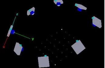
The UAV captured the images from eight positions that are aimed towards the calibration field (see Figure 4), similar to the study done by Pérez et al. (2011). The UAV was set to manual mode when being flown at the fixed height of 15 and 25 metres using GPS and an altimeter on the UAV platform. Figure 5 shows the camera positions as displayed in Australis software from a 45-degree angle.
Figure 4. Eight camera positions and directions
Type of the parameter used (object distance)
1.5 m 15m 25m
Mean of error percentage 0.0282% 0.0134% 0.0068% Minimum error value
(mm)
0.0061 0.1517 0.0654
Maximum error value (mm)
0.5692 0.9477 0.6142
Type of the parameter used (object distance)
1.5 m 15 m 25 m
Mean of error percentage
0.0112% 0.0208% 0.0157%
Minimum error value (mm)
0.0262 0.4265 0.8312
Maximum error value (mm)
3.1141 4.9752 3.7771 3. RESULTS AND ANALYSIS
There were three camera distances for the camera calibration and five observations were set up at each camera distance. The final results of the parameter values obtained from the camera calibrations are tabulated in Table 4 for 1.5 metres, Table 5 for 15 metres, and Table 6 for 25 metres.
Table 4. Parameter values (mm) for 1.5 metres C 2.06E+01
XP -1.41E-01 YP 7.02E-02 K1 4.14E-04 K2 -7.21E-07 K3 -7.20E-10 P1 3.81E-05 P2 3.88E-05 B1 -1.16E-03 B2 7.63E-05
Table 5. Parameter values (mm) for 15 metres C 2.06E+01
XP -1.43E-01 YP 8.31E-02 K1 3.52E-04 K2 8.28E-09 K3 -3.38E-09 P1 4.84E-05 P2 -1.84E-06 B1 1.94E-03 B2 -1.75E-04
Table 6. Parameter values (mm) for 25 metres C 2.06E+01
XP -1.74E-01 YP 2.32E-03 K1 3.51E-04 K2 2.86E-08 K3 -3.63E-09 P1 3.95E-05 P2 3.23E-05 B1 -3.92E-04 B2 -8.44E-05
Table 7. 3 sets of 1.5-metre accuracy assessment
Figure 5. Mean of error percentage for 1.5 metres
Figure 5 shows the bar graph of the mean of error percentage for the 1.5-metre image mapping process using 1.5, 15, and 25 meters of object distance parameters. The 25-metre object distance parameter used for the image mapping was the most accurate, followed by 15-metre object distance, and lastly 1.5- metre object distance.
Table 8 shows the accuracy assessment for 15-metre image mapping using different camera calibration parameters and the ensuing bar graph in Figure 6 reflects the accuracy assessment in Table 8.
Table 8. 3 sets of 15-metre accuracy assessment
Eight convergent images at 1.5, 15, and 25 metres of object distances or UAV flying heights were used to check the image mapping measurement accuracy of three of object distances. In Australis software, each calibration parameter was used at different object distances according to the UAV flying height to process the image mapping and check the measurement accuracy. The accuracy was assessed using the error percentage calculation in equation (1).
(1)
All the results of the accuracy assessment for 1.5-metre, 15- metre, and 25-metre image mapping are displayed in Table 7, 8, and 9, respectively. Table 7 shows the accuracy assessment for 1.5-metre image mapping using different camera calibration parameters and Figure 5 exhibits the accuracy assessment in the form of a bar graph.
Figure 6. Mean of error percentage for 15 metres
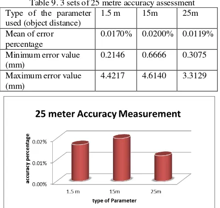
Type of the parameter mapping using different camera calibration parameters and Figure 7 depicts the accuracy assessment from Table 9.
Table 9. 3 sets of 25 metre accuracy assessment
Figure 7. Mean of error percentage for 25 metre
Figure 7 shows the bar graph for the mean of measurement error percentage for the 25-metre image mapping process using 1.5 and 25 meters of object distance parameters. The 25-metre object distance parameter used for image mapping was the most accurate, followed by the 1.5-metre object distance, and lastly the 15-metre object distance.
4. CONCLUSION AND RECOMMENDATION
The results showed the relationship between image mapping accuracy and the camera parameters used. The camera parameter at 25-metre object distance was the optimum distance for the best mean accuracy for 1.5-metre and 25-metre image mapping. The camera parameter at 1.5-metre object distance parameter resulted in the best mean accuracy for 15-metre image mapping only. In conclusion, the camera calibration at several camera distances should be applied to acquire better accuracy in mapping, and the best camera parameter for UAV mapping should selected for highly accurate mapping measurement
From this research, there are some limitations in camera calibration and mapping, in which both processes require a very large calibration platform on a wide area. The tools and area in this study were not fully equipped for longer and large interval object distances. The UAV flying heights proposed for acquiring images for calibration and mapping in future studies are 15 metres, 30 metres, 45 metres, 60 metres, 75 metres, 90, metres, 120 metres, and 180 metres. These camera distance intervals could be compared with the findings of this study. Furthermore, the data of the current study were processed using Australis software only; thus other software can be used in future studies to compare the camera parameters and mapping accuracy. Lastly, in order to minimize error during the map conversion process such as from exterior orientation to absolute orientation, the conversion process could be further examined for a more significant research.
ACKNOWLEDGEMENT
The authors acknowledge the support and contribution received from the Ministry of Higher Education (MOHE) and Faculty of Geoinformation and Real Estate, Universiti Teknologi Malaysia (UTM). The authors would also like to thank Innovative Engineering Alliance, Universiti Teknologi Malaysia, for providing the fund from vote number 4L149 to enable this study to be carried out.
REFERENCES
Kerle, N., Heuel, S., & Pfeifer, N. 2008. Real-Time Data Collection and Information Generation Using Airborne Sensors (pp. 43-74). Taylor & Francis/Balkema: Leiden, The Netherlands.
Eisenbei, H. 2009. UAV Photogrammetry. Inst. für Geodäsie und Photogrammetrie.
Sauerbier, M., Siegrist, E., Eisenbeiss, H., Demir, N., & Cloud, P. 2011. The Practical Application of UAV- Based Photogrammetry Under Economic Aspects. International Archives of the Photogrammetry, Remote Sensing and Spatial Information Sciences, Volume XXXVIII-1/C22, 2011 ISPRS Zurich 2011 Workshop, 14- 16 September 2011, Zurich, witzerland, XXXVIII (September), 14–16.
Weng, J., Cohen, P., and M. H. 1992. Camera calibration with distortion models and accuracy evaluation. IEEE Trans, Pattern Anal, Mach, Intell, vol.14,no.10, October 1992, pp.965-980.
Remondino, F., and Fraser, C. 2006. Digital Camera Calibration Methods, 266–272.
Pan, M., and Zhu, G. 2010. A Novel Method for the Distortion Modification of Camera Lens. 2010 International Conference on Optoelectronics and Image Processing, 2, 92–95.
Lichti, D. D., & Qi, X. 2012. Range camera self-calibration with independent object space scale observations. Journal of Spatial Science, 57(2), 247–257.
Pérez, M., Agüera, F., C. F. 2011. Digital Camera Calibration Using Images Taken From An Unmanned Aerial Vehicle. International Archives of the Photogrammetry, Remote Sensing and Spatial Information Sciences, Conference on Unmanned Aerial Vehicle in Geomatics, Zurich, Switzerland, XXXVIII, 1–5.
Chiang, K.-W., Tsai, M.-L., & Chu, C.-H. 2012. The development of an UAV borne direct georeferenced photogrammetric platform for Ground Control Point free applications. Sensors (Basel, Switzerland),12(7), 9161–80.
Tahar, K. N. 2012. Aerial terrain mapping using unmanned aerial vehicle approach. ISPRS Congress, Volume XXXIX-B7, 2012., 25 August – 01September 2012, Melbourne, Australia, (September), 493–498.
Jimenez, P. L., & Agudelo, D. 2015. Validation and Calibration of a High Resolution Sensor in Unmanned Aerial Vehicles for Producing Images in the IR Range Utilizable in Precision Agriculture. American Institute of Aeronautics and Astronautics (AIAA) SciTech, Kissimmee, Florida.
Zhou, Q., & Liu, J. 2015. Automatic orthorectification and mosaicking of oblique images from a zoom lens aerial camera. Optical Engineering, 54(1), 013104-013104.
Mohamed M.R. Mostafa and Klaus-Peter Schwarz. 1999. An Autonomous System for Aerial Image Acquisition and Georeferencing. American Society of Photogrammetry and Remote Sensing Annual Meeting, Portland, Oregon, May (pp. 17-21).
Liu, Ping, Xi Chen, and L. Y. 2011. An Approach of System Calibration for UAV Photogrammetry. Society of Photo-Optical Instrumentation Engineers (SPIE) Conference Series. Vol. 8200.
Pérez, M., Agüera, F., C. F. 2011. Digital Camera Calibration Using Images Taken From An Unmanned Aerial Vehicle. International Archives of the Photogrammetry, Remote Sensing and Spatial Information Sciences, Conference on Unmanned Aerial Vehicle in Geomatics, Zurich, Switzerland, XXXVIII, 1– 5.
Rehak, M., Mabillard, R., & Skaloud, J. 2013. A micro-UAV with the capability of direct georeferencing. ISPRS- International Archives of the Photogrammetry, Remote Sensing and Spatial Information Sciences, 1(2), 317-323.
Skaloud, J., Rehak, M., & Lichti, D. 2014. Mapping with MAV: Experimental Study on the Contribution of Absolute and Relative Aerial Position Control. ISPRS-International Archives of the Photogrammetry, Remote Sensing and Spatial Information Sciences, 1(1), 123-129.
Pfeifer, N., Lichti, D., Böhm, J., & Karel, W. 2013. TOF Range-Imaging Cameras. In Fabio Remondino & D. Stoppa (Eds.), Springer Berlin Heidelberg. 2013. 117. Berlin, Heidelberg.
Chow, J. C. K., & Lichti, D. D. 2013. A Study of Systematic Errors in The PMD CamBoard Nano. (Fabio Remondino, M. R. Shortis, J. Beyerer, & F. Puente León, Eds.), 8791, 87910X– 87910X–10.
Shortis, M. R, Clarke, T. A. & Short, T. 1994. A Comparison of Some Techniques for The Subpixel Location of Discrete Target Images. SPIE 2350, Videometrics III: 239-250.
Ahn, S. J., Warnecke, H. J. & Kotowskis, R. 1999. Systematic Geometric image Measurement Errors of Circular Object Targets: Mathematical Formulation and Correction. Photogrammetric Record. 16(93): 485-502.
Fraser, C. S. & Shortis, M. R. 1995. Metric Exploitation Of Still Video Imagery. Photogrammetric Record. 15(85): 107-122.