METHOD FOR MEASURING LENS DISTORTION BY USING PINHOLE LENS
J. Reznicek
CTU in Prague, Civil Engineering Faculty, Dept. of Geomatics, Thakurova 7, 166 29 Prague 6, Czech Republic [email protected]
KEY WORDS: Metrology, Vision, Camera, Calibration, Correlation, Distortion, Pinhole
ABSTRACT:
In photogrammetric applications, the measurements are conducted on images given by optical imaging systems (cameras). In order to ensure the demanded accuracy, those cameras have to be well calibrated geometrically. A new method for measuring glass lens distortion based on using distortion-free pinhole lens is proposed, where the measure of the distortion progress is derived by comparing two images of the calibration field, given by pinhole lens and glass lens. Presented approach to measuring the lens distortion provides directly the deviations of corresponding target images given by the pinhole lens and the glass lens, therefore the method is not limited by pre-defined functional model describing the distortion progress. The modelling of the distortion can be done a posteriori, by using tabulated distortion values. The proposed method for measuring lens distortion is applied in an experimental investigation leading to the confirmation of the validity of the theoretical development. The result of the investigation derives a promising new possibility for accurate lens calibration.
1. INTRODUCTION
1.1 Motivation
Camera calibration has been one of the most extensively researched topics in the field of photogrammetry and computer vision in last decades. There exists a plethora of prior work on each of the sub-topic concerning camera calibration methods. It seems that there is no other approach to the problem of camera calibration that would not have been already discovered and investigated. While doing some other research with the distortion-free pinhole lens, we conceived the thought of using this component for measuring of the (glass) lens distortion. After reviewing both the photogrammetric and the optical literature we did not find any mention about using pinhole lens for that kind of measurement. Thus, we decided to investigate the possibilities and limitations of this approach and to propose a new method for measuring lens distortion.
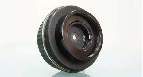
Figure 1. The pinhole lens with Canon bayonet mount
1.2 Interior Orientation
The interior orientation (IO) elements can be defined as “All characteristics that affect the geometry of the photograph” (Slama et al., 1980). The most important elements of IO include the following: sensor dimensions, principal distance, principal
point position and lens distortion characteristics. The list of all characteristics varies with different types of cameras. For example, airborne cameras are usually assembled from much more components then standard metric cameras for close-range photogrammetry and therefore needs much more parameters for the characterization of the interior geometry. Thus, depending on the camera type and demanding accuracy, additional characteristics could be needed: fiducials, axis scale, reseau coordinates, point spread function (PSF), sensor unflatness characteristics, sensor noise characteristics, forward motion compensation characteristics, etc.
This paper is focused primarily on measuring lens distortion. Under certain circumstances, which will be clarified later, the proposed method could be also used for measuring principal distance and principal point position. All other elements of the IO will not be considered in the paper in order to clarify the basic relations.
1.3 Lens Distortion
Lens distortion is a natural property of the optical system (OS) consisting of a glass elements, inducing displacement of the centroid of the PSF given by the object point projection, from the position given by an ideal OS. This definition can be described functionally as:
(1)
where are the image coordinates of the PSF centroid corresponding to ideal OS, are the image coordinates of the PSF centroid corresponding to glass OS and function with parameters is the mapping of the image space given by ideal OS, to the image space given by glass OS. The ideal OS is in this context a best approximation of glass OS. The word “best” implies that various approaches to that approximation exist. Our approach will be presented in Section 3.2.1. The lens calibration is therefore a process of finding the function and parameters . Even if the function and parameters are theoretically known from the lens design project, which is rarely the case, in The International Archives of the Photogrammetry, Remote Sensing and Spatial Information Sciences, Volume XL-5, 2014
practice, the manufacturing errors (e.g. centering error in lens elements assembly) in producing the lens prevent their use for highly accurate applications. The demand for a priori known lens distortion description in an analytical form is usually driven by the use of an analytical approach to the camera calibration (e.g. in-situ calibration, self-calibration), firstly presented by well-known photogrammetrist Duane C. Brown in his work from 1956.
Our approach to measuring the lens distortion directly provides the deviations of the corresponding target images given by glass OS and ideal OS. Having the dataset of deviations a priori, it is possible to choose an arbitrary mathematical model that best approximates the distortion progress, without worrying about correlations between the IO and EO (exterior orientation) elements and the physical nature of the lens.
1.4 Related Work
The overview of most common techniques for camera calibration will be given here. We divide those methods into a two groups. The first group are methods that enable to measure the lens distortion directly. The second group contains a methods based on computing parameters of an a priori given mathematical calibration model.
First group:
Goniometer and multi-collimator based method Stellar method
Second group:
Projective invariant based methods (plumb-line, cross-ratio, vanishing points)
Targets resection (In situ, self-calibration)
1.4.1 Goniometer Method: There are basically two approaches. First is based on the visual inspection of the nodes of the plane parallel grid plate clamped at the focal plane of the camera, while the second is based on projecting targets on the image plane. The first approach (historic) is limited only to analog cameras, because it is not possible to remount the digital sensor. instrument and the photographic plate is interchanged with the plane parallel grid plate measured with a high accuracy. The system is then autocollimated. Each node of the grid of the plane parallel plate is then observed by the telescope and the corresponding angle is recorded. Then, those data are used for solving the parameters of the interior geometry of the camera.
In the second case, the cross-hair of the theodolite or other pattern is projected on the image plane and measured on comparator (analog) or automatically (digital) with a subpixel precision. The measurements are usually conducted in a four different planes – horizontal, vertical and two diagonals. Since the autocollimation of the digital camera is problematic, the measurements are usually performed twice with 180° rotated camera head and the following adjustment of the interior orientation elements is expanded by including three rotation angles as unknowns.
1.4.2 Multi-collimator Method: Multi-collimator consists of an array of collimators (simulating infinity targets) accurately aligned in such a way that all collimator axes intersect in a single center. The autocollimating telescope is used to position the camera in such a way that the focal plane is perpendicular to the center collimator. The calibration procedure consists of a several steps. The camera is placed on the calibrator instrument and aligned in such a way, that the entrance pupil of the lens is located at the point of intersection of the array of collimators and the focal plane is perpendicular to the axis of the central collimator. Then, the photographic plate is exposed. The image coordinates of the targets given by the collimators are then used for solving the parameters of the interior geometry of the camera. The image of the central collimator is the principal point of autocollimation (PPA).
More information about methods employing goniometer or multi-collimator device can be found in (Cramer, 2004), (Slama et al., 1980), (Clarke et al., 1998) or (Sandau et al., 2010).
1.4.3 Stellar Method: The Stellar method of camera calibration was frequently used during 1950’s by Hellmut Schmid and Duane C. Brown, for calibrating the ballistic cameras used for tracking test rockets. This method takes advantage of the stars, which can be considered as ideal targets at the infinity distance, with the position given in the astronomical tables. If the camera is placed in the known location (longitude and latitude) and directed to the zenith, then the image of the sky gives several hundreds of the star images, which, after atmospheric corrections, can be used for solving the parameters describing the interior camera geometry deviations from the projective geometry model. The detailed description of this method can be found in (Fritz et al., 1974).
1.4.4 Plumb-line Method: The Plumb-line method for camera calibration was introduced by Duane C. Brown in his most cited article "Close-Range Camera Calibration" (Brown, 1971). This method is based on using the straightness invariant of the projective geometry. The calibration field, consisting of a set of plumb-lines, is imaged by the camera being calibrated. The images of the plumb-lines are due to the lens distortion distorted, which is used for the analytical estimation (by using adjustment with constrains) of the parameters describing the lens distortion. The principal point position can be also computed, but with a lower precision (the precision of the estimate depends primarily on the magnitude of the distortion. Higher distortion leads to a higher precision). The principal distance cannot be recovered here. The method is well suited for calibrating cameras used for close-range photogrammetric applications.
1.4.5 Cross-ratio Invariant Method: In 2003, Zhang et al. published an article in which they proposed a method for camera calibration based on a cross-ratio invariant. They propose to capture the image of a chessboard-pattern calibration field, chose any collinear four points (corners of the squares) and compute two cross-ratios. One corresponds to the object space (real chessboard) and the second to the image space. The differences between those two values are attributed to the lens distortion, which is analytically estimated by using constrained adjustment. Ricolfe-Viala et al. (2010) improved the estimation by incorporating all possible combinations of cross-ratio that can be found on a chessboard-pattern calibration field. Unlike Zhang et al., who derived the cross-ratio formulation separately for each coordinate x and y, Ricolfe-Viala et al. derived only one cross-ratio formulation using absolute value of distances (e.g. ̅̅̅̅ instead of ̅̅̅̅̅ and ̅̅̅̅̅̅).
1.4.6 Vanishing Points Method: This method is based on the relations between the perspective projection and vanishing points. Among many approaches, we will describe the method proposed in (Tan et al., 1995), which is based on recovery of the IO elements by using perspective views of a rectangle. The method requires only a very simple calibration field which consists of a four targets composed in the shape of the rectangle and lying in a common plane. In projective geometry, the view of the rectangle constitutes two vanishing points. Each of them defines the vector, having the origin in the projection center. Those vectors are perpendicular in Euclidean geometry, which means that the dot product of those two vectors has to be zero. This can be written as a conditional equation, where each of the two vectors is composed from measured coordinates of the rectangle corners and IO elements. Each view of the rectangle constitutes such condition which leads to the system of equations. This system of equations is then solved for example by least square adjustment. Different approach can be found in (Pajdla et al., 1999).
1.4.7 Methods based on Target Resection: The methods based on targets resection are based on solving the well-known projective equations expanded by the set of additional parameters of a certain polynomial, which characterize the deviation of the real interior geometry of the camera from the ideal central projection. The projective equations expresses the relation between the 3D Cartesian coordinates of the targets in object space and the 2D coordinates of the corresponding targets in image space. The procedure of the calibration process is usually based on acquiring a set of images of the targets, taken from the different views.
If the targets are surveyed with demanding accuracy and spread around the measured object, than those targets are known as “control points” or “ground control points” and such arrangement is known as “In situ” calibration method. The calibration procedure is here performed simultaneously with the object reconstruction. In case of an aerial photogrammetry, the ground control points are set up on the ground and measured with GPS or surveyed with theodolite. In case of a close range photogrammetric applications, the control points are usually given by a proprietary made highly accurate instruments in the shape of crosses or cages and bars.
Calibration method known as “self-calibration” is able to do the simultaneous reconstruction and calibration even without known 3D Cartesian coordinates of the targets, if the geometry of the configuration (Fraser, 1984) and additional calibration polynomial is designed properly. This is now extensively used in the field of “computer vision” for “structure from motion” method. Both above mentioned methods can be of course used for the purposes of the camera calibration only.
The most important investigations in the field of the simultaneous camera calibration and object reconstruction were made several decades ago by famous photogrammetrist Duane C. Brown within his company DBA Systems, Inc. (now Geodetic Systems, Inc.) and his findings, e.g. (Brown, 1956, 1971) are considered today as a standard. More information about the method of self-calibration can be found in (Fraser, 1997) or (Pollefeys et al., 1999). Great source of information is provided in books (Gruen, 2001) and (Luhmann, 2007).
2. DESCRIPTION OF PROPOSED METHOD
2.1 Main Idea
The best OS for the use in photogrammetry, would be an ideal OS having both principle planes coincident. In reality, this can be realized by an OS with pinhole lens (see Figure 2, left). However, the numerical aperture of a pinhole lens is very low, which brings a high amount of noise on sensor during long exposures. Additionally, the resolution performance given by pinhole lens is, due to the diffraction phenomenon, very poor comparing to the glass lens performance. These are the main drawbacks of the pinhole OS, preventing its wider use in practice. On the other hand, if the imaging process is limited only to small dots surrounded by a uniform background, then the resolution performance is not needed. Moreover, the long exposures can be shortened by introducing the active light targets providing direct light. These two enhancements enable us to use the pinhole OS for lens calibration. Imaging with the pinhole lens provides two significant advantages: The mapping of the 3D object space to a 2D image space is the outright realization of the projective geometry and is free of any distortion.
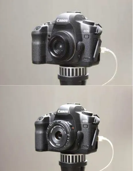
Figure 2. Pinhole optical system (top) and glass optical system (bottom)
The main idea of the proposed method is based on comparing two images of the calibration field targets acquired by stable OS being calibrated, where the first image is acquired with a small change – the glass lens is replaced with the distortion-free pinhole lens.
2.2 Calibration Procedure and Arrangement
The list of all instruments used for the proposed lens calibration procedure is as follows: The OS being calibrated, consisting of The International Archives of the Photogrammetry, Remote Sensing and Spatial Information Sciences, Volume XL-5, 2014
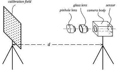
a sensor mounted in a camera body and the glass lens. The camera body needs to be equipped with such a lens mount (usually screw-threaded or bayonet type), that provides interchangeability of the lens. Pinhole lens must have the same type of lens mount and with a similar focal length (“focal length” of pinhole lens is given as a flange focal distance of the camera body + flange-to-pinhole center distance). The planar calibration field consisting of tens of uniformly distributed small (e.g. 2 mm) active light targets on a black background. The calibration field is situated in front of the camera in the working distance given by demanded magnification and is parallel to camera sensor (see Figure 3). The number and spacing of targets is selected in such a way, that target images are uniformly distributed all over the sensor area.
The procedure of the proposed method comprises several simple steps. The calibration field is captured from the single tightly fixed pose two times. The first image is acquired with the pinhole lens attached to the camera body. Then, the pinhole lens is carefully interchanged with the glass lens and the second image is acquired (from the same fixed pose). The tight fixture of the camera body is necessary in order to prevent any movement within the lens change. In the next step, the image coordinates of target images are detected on both images. Therefore, two different sets of image coordinates for same targets are given. The differences in image coordinates for corresponding targets between both sets are function of the differences of the IO elements (e.g. principal distance, principal point, lens distortion) between pinhole OS and glass OS. By proper treatment, it is possible to get those differences of the IO elements. If the first set of image coordinates is transformed (using scale and translation) to the second in such a way, that the Euclidean norm (also known as a L2-norm, or least squares) of the residuals is minimal, we get the differences of the principal distance and principal point. Then, the vector differences between corresponding target images after the transformation process can be attributed directly to the lens distortion, because the pinhole OS has no distortion. More details about the transformation process will be given in Section 3.
Figure 3. Arrangement of the proposed calibration method
If the repeatability of the lens mount is precise enough, then the differences of the principal distance and principal point can be added to the corresponding values of the pinhole OS, which give us, in addition to lens distortion, an estimate of the principal distance and principal point of the glass OS. However, those elements of IO of the pinhole OS have to be known.
3. THEORETICAL DEVELOPMENT
In this section, we describe the relations between image coordinates given by pinhole OS and glass OS. Those relations are important for understanding of the proposed calibration procedure.
3.1 Ideal Optical System
Besides pinhole and glass OS, there is also an ideal OS, which is intended as a best approximation of the glass OS. The ideal OS is only virtual and does not exist in reality. The introduction of an ideal OS has the advantage, that the transformation process between the pinhole OS and the glass OS can be divided into a two parts:
(2)
(3)
where the first part (eq. 2) is a simple linear transformation (in case of planar calibration field), denoted , between the pinhole OS ( ) and the ideal OS ( ).
The second part of the transformation process is realized by the function with parameters . Function represents the non-linear part of the distortion of the glass OS induced by the optical and mechanical aberrations.
3.2 Transformation Between Pinhole and Ideal Optical System
For in equation 2, we can write (Reznicek, 2013):
[
]
(4)
The solution of the system of 2×N equations 2 (2 stands for x and y while N is the number of targets) with a three unknown parameters and cannot be solved directly by using image coordinates , because those coordinates do not actually exist as was stated previously.
3.2.1 Position of an Ideal Optical System: Inasmuch as the ideal OS is only an approximation of the glass OS, there has to be chosen some criterion, which defines the exact position of the ideal OS in relation to the glass OS. For example, following criterion can be chosen: the Euclidean norm (also known as a L2-norm, or least squares) of the difference of the coordinates corresponding to glass OS and coordinates corresponding to the ideal OS is minimal. This can be written as:
∑‖ ‖
(5)
After a substitution of from eq. 2 we get:
∑‖ ‖
(6)
Finally it is possible to estimate the unknown parameters and by using relation 6.
Our approach to defining the position of the ideal OS in relation to the glass OS is actually a more general form of defining "principal point of best symmetry" (PPS) and "calibrated focal length" (CFL) – well-known terms in photogrammetry.
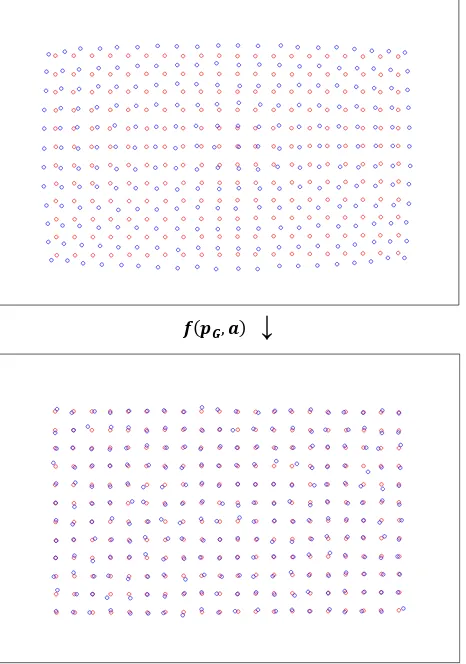
↓
Figure 4. Illustration of the transformation (eq. 2) of the target images given by the pinhole OS (Red circles on the top image) to target images (Red circles on the bottom image. Those target images do not exist in reality) given by the ideal OS. Blue circles denote the target images given by the glass OS
3.3 Transformation Between Glass and Ideal Optical System
Transformation between the glass and ideal OS is described by the formula 3. Having function it is possible to estimate the unknown parameters . Same criterion (Euclidean norm) as was used in previous section can be used here. Therefore:
∑‖ ( )‖
(7)
The following condition has to be fulfilled, if demanding accuracy δ shall be reached:
∑‖ ( )‖
(8)
where is given by eq. 2 and where δ depends on demanding accuracy. If using certain function does not satisfy the
condition 8, a different one has to be chosen. The lower value of δ leads to a more complicated functions.
Our approach to measuring the lens distortion directly provides the deviations of the corresponding target images given by glass OS and ideal OS, hence the function approximating the distortion progress with respect to local deformations can be arbitrary chosen. Moreover, no function is needed, if we tabulate the distortion values by proper interpolation method.
↓
Figure 5. Illustration of the transformation (eq. 3) of the target images given by the glass OS (Blue circles on the top image) to the position given by the ideal OS (Red circles). The amount of residual vectors after the transformation depends on the applicability of the function . Blue circles on the bottom image denotes the corrected position after transformation
4. EXPERIMENT
We have conducted an experiment in order to prove the theoretical development of our proposal. All computations were performed by using self-written program in Matlab language. Each acquired image was separated from raw Bayer scheme into a four individual R-G1-G2-B channels and only the Green1 channel was used (such approach is necessary due to chromatic aberration).
4.1 Equipment
Calibration Field: The calibration field is a planar wooden desk (800×1200 mm) with 1 440 regularly spaced targets. The targets are represented by a black dot (5 mm in diameter) printed on a white sheet of paper of same dimensions as the wooden desk. (Originaly, we have constructed a different calibration field, consisting of 240 small (2 mm in diameter) active light targets driven by led diodes. However, this field produces some undiscovered small systematic error and cannot be used yet.)
Digital Camera Body: Canon EOS 5D Mark II; pixel size: 6.4 µm; sensor size: 5792×3804 pixels; sensor format: full-frame (approximately 36×24 mm).
Glass Lens: Canon EF 40 mm F2.8 STM; the lens focusing mechanism was fixed with a tape to focused distance of 1 800 mm (target-to-sensor). Aperture was set to 8.
Pinhole Lens: The pinhole lens was assembled from components ordered from co. Edmund Optics. The steel bayonet mount was taken from an old broken Canon lens. The pinhole diameter is 300 µm; f-number is approx. 183. Principal distance is approx. 55 mm (see Figure 1).
4.2 Procedure
The calibration field was captured from the single tightly fixed pose (heavy tripod with fixing screw) two times. The first image was acquired with the pinhole lens attached to the camera body. Then, the pinhole lens was carefully interchanged with the Canon 40 mm glass lens and the second image was acquired (from the same fixed pose). The distance of the calibration field from camera sensor was set to 1 800 mm, which defines magnification m = 0.023.
In the next step, the image coordinates of all target images were detected on both images. Therefore, two different sets of image coordinates for same targets are given ( and ). Now, by using relation 6 and proper estimator, we have computed the unknown parameters and , which constitutes transformation matrix . This gives us image coordinates in the system of ideal OS (eq. 2). The differences given by
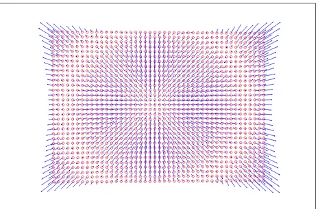
are directly the distortion values of Canon 40 mm lens for magnification m. The visualisation of the distortion values is shown in Figure 6.
We have also computed the radial distortion parameters ( and ) of a well-known polynomial by using the relation 8, where (Brown, 1956, 1971):
(9)
where:
(10)
where is a x-component of and is a x-component of the principal point of the glass OS (similarly for y-component). The results are given in Table 1. The visualisation of the residual vectors after correcting the image coordinates from distortion by using radial distortion polynomial is shown in Figure 7.
Table 1. Estimated radial components of the distortion polynomial
Proposed method Photomodeler
[mm–2] 4.389e–005 4.884e–005 [mm–4] –5.187e–008 –5.639e–008
4.3 Validation
Validation of the results given by proposed method was perfomed by calibrating the same camera (glass OS) with unchanged configuration in software Photomodeler v6, which uses self-calibration method (see Section 1.4.7). For this purpose, a total amount of 12 images of a planar field, consisting of a 144 targets (printed black dots), were captured from the distance approximately equal to 1500–2500 mm. In the software options, only coefficients and were selected for estimation (besides principal distance and principal point). The results are given in Table 1. The computation resulted in an overall RMS of 0.8 µm.
Figure 6. Illustration of the distortion values. The scale of the vectors is 1:50. The calibration field do not cover the whole format of the sensor due to difference in principal distance of the pinhole and glass OS (approx. 55/40)
Figure 7. Illustration of the residual vectors after correcting the image coordinates from distortion by using radial distortion polynomial. The scale of the vectors is 1:100
5. CONCLUSION
A new method for measuring lens distortion has been proposed and validated. The validation method, which uses target resectioning, has a certain limitations: Due to the nature of the resectioning, the magnification m varies target to target. Therefore, it is not possible to set the proper validation criteria, because each magnification requires different values of distortion characteristics. However, we can conclude (based on the results given in Table 1), that the proposed method is valid. The magnitude of the similarity in the results is obvious. The analysis of the error propagation in the proposed method is beyond the scope of this paper and will be presented next time.
The Figure 7 clearly shows the systematic effect in the bottom-right and upper-left corners, which is caused by the decentering distortion. We did not compute the decentering distortion because the glass lens with bayonet mount is not stable enough. Therefore, those characteristics can vary quite much. It is a limitation of the used equipment and not the method.
The principal distance of the pinhole OS should be close to the principal distance of the glass OS. The detailed description of the error given by the difference is given in (Reznicek, 2013).
It should be also mentioned, that the principal point of the glass OS (precisely: principal point of the best symmetry) is always advantageous as no additional parameters, that could influence the reliability of the estimation, have to be considered. Those additional parameters are usually the elements of EO which in certain camera component configuration highly correlates with the lens distortion characteristics. Furthermore, our approach based on measuring relative values given by comparison of two images do not require absolute position of the calibration field targets which reduces additional sources of error given by target surveying. Particularly the lens distortion variation induced by change in magnification or aperture can be easily measured.
Our approach to measuring the lens distortion provides directly the deviations of corresponding target images given by the glass OS and the ideal OS, therefore the method is not limited by pre-defined functional model describing the distortion progress. The modeling of the distortion can be done a posteriori, by using tabulated distortion values.
The main drawback of the proposed method is the requirement of changing the lens, which leads in most cases to the significant change of the principal distance and principal point. The issue of mechanical stability and repeatability of the OS components is described in more detail in (Reznicek, 2013). Another significant limitation of the method lies in the fact, that wider field of view (FOV) cannot be calibrated. The pinhole OS is not able to refract the light, therefore the smallest possible principal distance of such OS (or more intuitively: the largest FOV) is limited by the flange focal distance of the camera body.
ACKNOWLEDGEMENT
This research was supported by the Czech Ministry of Culture, under grant NAKI, no. DF13P01OVV002 (New Modern Non-invasive Methods of Cultural Heritage Objects Exploration).
REFERENCES
Brown, D. C., 1956. The Simultaneous Determination of Lens Distortion of a Photogrammetric Camera. AF Missile Test Center Technical Report No. 56-20, Patric AFB, Florida, USA.
Brown, D. C., 1971. Close-Range Camera Calibration. In: Photogrammetric Engineering 37 (8), pp. 855–866.
Clarke, T. A. and J. F. Fryer., 1998. The development of camera calibration methods and models. In: Photogrammetric Record, 16 (91), pp. 51–66.
Fritz, L. W. and H. H. Schmid., 1974. Stellar Calibration of the Orbigon Lens. In: Photogrammetric Engineering 40 (1), pp. 101–115.
Gruen, A., 2001. Calibration and Orientation of Cameras in Computer Vision. Springer Series in Information Sciences (Book 34), Published by Springer.
Luhmann, S., 2007. Close Range Photogrammetry: Principles, Techniques and Applications. Published by Wiley.
Magill, A. A., 1954. Variation in Distortion with Magnification. Journal of Research of the National Bureau of Standards, Vol. 54, No. 3, March 1955, Research Paper 2574, pp. 135–142.
Pajdla, T. and M. Urban., 1999. Camera Calibration from Bundles of Parallel Lines, CMP Technical Report, Center for Machine Perception, Department of Cybernetics, Czech Technical University in Prague.
Pollefeys, M., R. Koch and L. Van Gool., 1999. Self-Calibration and Metric Reconstruction Inspite of Varying and Unknown Intrinsic Camera Parameters, In: International Journal of Computer Vision. 32 (1), pp. 7–25.
Reznicek, J., 2013. Method for Measuring Lens Distortion. Doctoral Thesis. Czech Technical University in Prague.
Ricolfe-Viala, C. and A. J. Sánchez-Salmerón, 2010. Correcting non-linear lens distortion in cameras without using a model. In: Optics & Laser Technology. 42, pp. 628–639.
Sandau, R., 2010. Digital Airborne Camera, Introduction and Technology. Published by Springer.
Slama, CH. C., CH. Theurer and S. W. Henriksen, 1980. Manual of Photogrammetry. Published by American Society of Photogrammetry, Falls Church, Virginia, USA, p. 244.
Tan, T. N., G. D. Sullivan and K. D. Baker, 1995. Recovery of Intrinsic and Extrinsic Camera Parameters Using Perspective Views of Rectangles. In: Proceedings of the British conference on Machine vision, Vol. 1, pp. 177–186.
Zhang, G., J. He and X. Yang, 2003. Calibrating camera radial distortion with cross-ratio invariability. In: Optics & Laser Technology, Volume 35, Issue 6, pp. 457–461.