Low cost 3D-modelling of a complex archaeological site using aerial photography in the
hinterland of Petra, Jordan
R. Emaus a, b *, R. Goossens b
a Udhruh Archaeological Project, Faculty of Archaeology, Leiden University, Netherlands – [email protected] b Deptartment of Geography, Ghent University, Krijgslaan 281 S8, 9000 Ghent, Belgium – [email protected]
Commission V, WG V/4
KEY WORDS: Udhruh, Roman Archaeology, Quarries, Photogrammetry, Aerial Photography, Kite
ABSTRACT:
Individual archaeological sites can sometimes show a complex morphology. One such site is the Roman quarries located one kilometre northwest of the Roman fortress at Udhruh, in the hinterland of Petra. In archaeology there are various platforms such as balloons, kites and unmanned aerial vehicles (uav's) from which low altitude aerial photographs can be taken that have been proven to work. All with their specific advantages above others in different circumstances. By designing a very distinct setup for the kite and optimizing the workflow accordingly, an effective and steady platform for the camera was created. The Quarries were photographed from the air and the images then provided enough material to accurately create a 3D model of the site.
* Corresponding author.
1. INTRODUCTION
Using photogrammetrical software a high resolution DEM or other surface model of a single archaeological site can be recorded accurately. One only needs photographs of the site with ample ground resolution, which in general means that the photographs have to be taken from a low altitude above the ground. In archaeology there are various platforms in use such as balloons, kites and unmanned aerial vehicles (uav's) from which low altitude aerial photographs can be taken that have been proven to work (Verhoeven, 2009). All have their specific advantages above others in different circumstances, mainly dependent on wind conditions and the platforms' logistical needs.
This paper presents a research effort into designing and optimizing a low-cost, effective and accurate way to record archaeological sites in the hinterland of Petra. In particular we will look into the choice of platform and materials that are best suited for this environment whilst still not too expensive and optimize the workflow in the field. Further, we will examine the processing of the data and eventually the accuracy of the model.
Individual archaeological sites can sometimes show a complex morphology that cannot be recorded easily with classical topometric instruments (Verhoeven et al, 2012). One such site is the Roman quarries located one kilometre northwest of the Roman fortress at Udhruh, Jordan. The quarries provide an excellent example of a site that has a very distinct morphology that needs to be recorded with great precision. A high resolution DEM of the site can provide a richer documentation than any total station survey can, and with similar accuracy.
2. BACKGROUND
The ancient city of Petra is located just west of the Jabal ash-Shara ridge, running in a north to south direction east of Wadi
'Araba (Figure 1). As part of the Jordan Rift Valley, Wadi Figure 1. Map showing the topography of Southern Jordan with
the locations of Petra and Udhruh.
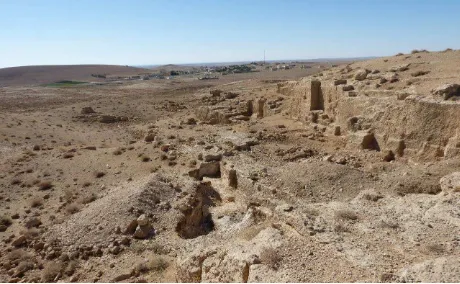
Figure 2. Part of the large Roman quarries northwest of Udhruh. Photograph by A. Gazenbeek.
'Araba is part of the 6000 km long fault system that runs from Northern Syria to East Africa. The main geological sequence in the Petra region is made up of Cretaceous limestone with impermeable sandstone under it. Because the geology is tilted towards the east, the eastern part of the region is largely made up of limestone while the sandstone is surfacing west of the ash-Shara ridge (Kherfan, 1998). Petra lies within one of the many valleys that have cut deep in the surfacing sandstone stretching west from the ridge. The soils are mostly made up of bare bedrock or stony soils. The landscape east of the ridge consists mainly of rolling hills and highlands that continue into the pre-desert plateau. Wide valleys extend eastward from the ridge into the pre-desert area where they create floodplain environments towards the al-Jafr Basin. The bedrock is mainly made up of limestone and marl. Soils mainly consist of alluvial sand and gravel deposits.
Based on the 6th century Petra Papyri, the hinterland of Petra can at least in easterly direction be estimated to have reached to about 20 kilometres from the city. Both Udhruh and Sadaqa by then still fell under the jurisdiction of Petra, suggesting a political and economic coherent region dominated by the antique city (Kouki, 2012). The transition from a highland environment to the pre-desert plateau can be roughly situated at the town of Udhruh, some 15 km east of Petra. Udhruh, identified as Augustopolis in the Petra Papyri, is mainly known for its second century Roman fortress (Kennedy, 2004). Already in Nabataean times the site probably acted as an important satellite station along the trade route into Petra, providing the desert caravans with water from the local spring and food from the local both dryland and irrigated fieldsystems (Abudanah, 2006; Driessen & Abudanah, 2013). Later, in the Byzantine and Islamic periods, Udhruh was still an important site as the many rural settlements in the hinterland of Petra became more concentrated into larger villages and towns such as
Augustopolis since the Byzantine period (Kouki, 2012). The area directly around Udhruh can therefore be seen as an important sub-region in the hinterland of Petra.
While there have been some small excavations within and around the fortress (Kilick, 1983 & 1986), Abudanah has investigated a wider region around Udhruh (Abudanah, 2006) and since 2011 an archaeological survey project has been set up to prospect the region more directly around and in relation to the fortress (Driessen & Abudanah, 2013). Next to the Roman fortress the area has shown to contain various archaeological sites such as water management and field systems, fortlets, watchtowers and the large quarries. The large quarries have yet to be investigated thoroughly but have probably supplied building material mainly for the building of the fortress itself. These quarries therefore have to be examined and documented precisely as part of the research into the large Roman fortress of Udhruh. Modelling the quarries is a first step in this process
3. CHOICE AND DESIGN OF KITE AND CAMERA
3.1 Choice of platform
3.1.1 Balloon: The variety of the wind-conditions can render
a helium balloon very unstable (Verhoeven et al, 2009). Next, balloons are easily damaged or punctuated on the ground by the local vegetation. Also, balloons need a supply of helium, which can be a logistical challenge to acquire locally and handle in the field.
3.1.2 UAV: The sometimes unpredictable winds also create
challenges for smaller uav's as they can be suddenly blown a distance away. In the event of a rough landing, the relatively delicate parts of a uav may easily be damaged by the sharp rocks and stones on the surface. Also, a uav can be very costly compared with the other platforms. Though, uav’s have been proven to work very well in other parts of the world (Verhoeven, 2009; Hendrickx et al, 2011).
3.1.3 Kite: In combination with the following advantages
and considerations the kite was selected as the platform to be used. First, the kite is naturally able to handle various wind conditions while maintaining the needed stability (Aber et al, 2002). Second, all parts of a kite are very easily repaired in the field with only some basic spare parts and a leatherman in case of a rough landing. Third, a kite is very low-cost and maintenance free when compared to other platforms as its parts are easily available all over the world and a kite doesn't need a supply of helium to fly. Fourth, there are no legal constraints on using kites whatsoever. In an increasing number of countries a permit is needed to fly a uav or there can be constraints on importing one into the country.
All of these disadvantages can of course be mitigated but for this region the kite is the best option. Perhaps uav's are feasible in longer running projects in the area or later on in the local Udhruh Archaeological Project.
3.2 Design of the Kite
In order to improve the functionality of the platform, a kite was chosen that can be manoeuvred very well by the use of two steering lines. The operator is therefore able to precisely manoeuvre the kite in virtually every location above the site to get the best coverage from just a few operating positions. This has the advantage that the operator doesn't have to walk across a site in order to cover it from the air as is normally the case with single-line operated kites. This is especially advantageous with sites that have limited accessibility or a difficult terrain such as the Roman quarries with steep cliffs and numerous holes in the ground (Figure 2). From a single operating position, a site can be covered from the whole wind-window of the kite (Figure 6). The wind-window of the kite can further by enlarged by using
longer steering lines. But this, of course, also effects the ground resolution of the imagery (see section 5.1).
Kites generally can provide the needed lift from a wind speed of 2 bft. and upwards. The only consideration that has to be made is the size of the kite in function of the average wind speed and the weight of the camera it has to lift; larger kites with lower wind speeds or heavier cameras and smaller kites with larger wind speeds or lighter cameras. Obviously, the kite mustn’t be too small or it simply won’t fly. But adversely, for safety reasons it better not be too large as well or one will be unable to handle the kite which pulls too hard on the person operating it, leading to disaster. Although a backup kite of 1.6 m2 was available during fieldwork, a kite of 2.1 m2 was used to take all the necessary imagery. This kite generally provided just enough lift in the mildest of wind conditions whilst still being controllable in some of the rougher wind conditions we experienced.
The length of the steering lines, and thus the maximum camera height, can be chosen in function of the wanted ground resolution and coverage. Both long (>50 meters) and short (<30 meters) steering lines have their advantages and disadvantages. When using relatively short steering lines the wind-window is of course also relatively small and the operator will have to use multiple operating points when a large area has to be covered. The advantage of shorter steering lines is that there is less of a delay in the steering of the kite, resulting in being able to manoeuver with greater precision. When the exactness of the flight plan is not so much of an issue but the terrain poses some difficulties, longer steering lines will be more advantageous. The operator will be able to cover a larger area not only because the actual wind-window is larger, but also because the kite can take imagery from higher altitudes. The latter advantage will have its detrimental effect on the ground resolution of course.
3.3 Design of the cradle
The camera has to be mounted to the kite in a way that it is stable and pointing in the right direction i.c. down to the earth. The cradle is made of simple iron strips that are bolted together in such a way that a small frame comes into being. The camera can then be mounted inside this frame using a single bolt or thumbscrew that fits in most cameras’ tripod screw threads. All space between camera and frame is then filled up with foam (usually an ordinary sponge that has been manually ‘customized’ to make a perfect fit). The foam provides some extra stability and protection for the camera. The weight of the cradle and camera now amounts to circa 1 kg.
Figure 3. The kite with cradle (side). Photograph by A.K. Helming.
Figure 4. The kite with cradle (front). Photograph by A.K. Helming.
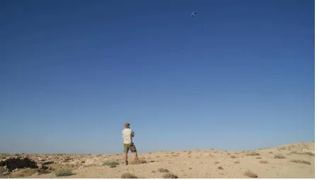
Figure 5. Operation of the kite. Photograph by M.H. Sepers.
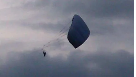
The cradle is then attached between the two steering lines of the kite with a rod so the kite won't collapse under the weight of cradle and camera that would otherwise pull the lines together. In case the wind drops completely the rod also makes sure the kite stays open and gently comes down like a parachute (Figure 4).
This construction also provides stability to the camera and prevents it from some unwanted movement. With the camera up in the air, the biggest problem is holding it as motionless as possible not to create any motion-blur in the imagery. With the cradle and camera attached to the two steering lines of the kite, the camera is automatically unable to swing in at least one direction; from left to right in the operators’ perspective, or the φ-pivot in classical aerial photography. Because this movement is firmly controlled by the two steering lines.
The movement of the cradle around the carbon rod to which it is attached, creating a swing to and from the operator (or the ω-pivot) now is the only unwanted movement within the whole system. Unfortunately, we have found no structural answer to this problem that doesn’t also create any difficulties in e.g. steering the kite. One partial solution however comes from the weight of the cradle; because it is relatively heavy, it automatically dampens all movement, especially sharp movements.
3.4 Choice of the Camera
The camera used was a Panasonic dmc-ft4. This is a standard off the shelf compact camera with zoom lens. Since this research was conducted to establish a workflow and acted as a feasibility study, the choice of camera was mainly driven by its ruggedness and cost. Especially because of the sometimes unpredictable winds we didn’t want to put an expensive
camera on the line before testing the whole workflow and outcome.
4. OPERATION OF KITE AND CAMERA
4.1 Operation of the Kite
The kite can then be operated by a single person (Figure 5) although a second person is required at the end and start of the flight. Contrary to single line kites, the double or even four lined kites have to be put airborne with their lines completely out; the length of the lines cannot be changed during flight. In order to put the kite airborne, the operator has to hold the steering lines, attached to a bar or other handles, while a second person holds the kite in such a position that it can catch the airflow and already generates some pull on the steering lines. This is important because the kite’s intrinsic stability and shape are created by the pull from the steering lines. Obviously, it is also important that the kite is instantly under control of the operator once it is airborne. Naturally, the kite then has to be at a distance from the operator to make sure the steering lines are already generating some pull towards the kite even before it is fully airborne.
Figure 6. The wind window: grey arrow indicating the wind direction and white arrows all possible kite movement.
area beneath that semi-circle. Of course these flight characteristics may or may not be problematic and have to be considered on a site to site basis.
During fieldwork, relatively long steering lines of 60 meter were used which enabled occupying less operating points and better overall coverage of the site. The disadvantage of these longer steering lines is the increase in drag on these lines, pulling the lines with the wind. Drag is caused by the wind blowing on the surface of the lines and although special lines were used, the sheer length of the used lines still created a significant amount of surface for the wind to create a drag. One of the more obvious signs of the drag is the curve the steering lines show between the operator and the kite. Whereas shorter steering lines (without drag) will show a much more straight line. The actual disadvantage of this drag is that the steering lines follow a longer path between kite and operator, and thus enable the kite to fly lower than theoretically possible. But the biggest drawback of the drag is the dampened and delayed response of the kite to the actions of the operator, leading to somewhat less control over the kite.
4.2 Operation of the camera
In order to take pictures from the kite, one has to remotely operate it or set it to take pictures at a predetermined interval. Although the latter is the easiest and cheapest we found it has some serious disadvantages. The main disadvantage is that the operator can’t see which part of the site is photographed exactly. Judging the position of the kite from the ground, the operator only has an approximate idea of the area the camera captures. Also, the exact instance the camera takes a image sensitivity, aperture and exposure time could not be set by the operator but where chosen by the camera computer anew for every picture. This of course produced imagery with
slightly varying characteristics regarding to aperture and exposure time which the camera computer thought was best for the imagery at the time. In general, though, the variation in the imagery characteristics turned out to be hardly problematic. Only some motion-blur in a few images could have been prevented by setting a better exposure time. The pictures with the motion-blur were excluded from further processing and again more imagery had to be taken with the kite to overcome the problem.
4.3 Flight Plan
The flight plan was designed to fly at the same altitude as much as possible. Thus describing an arc, from left to right in the operators’ perspective with the kite. Due to some variety in the wind conditions during flight, the kite had to be flown higher or lower as wind conditions were sometimes more favourable at those altitudes. This brought some variety in the ground resolution of the imagery, but, as unstable winds could be largely omitted, the camera could to some degree be held free of unwanted motion in those stable wind resolution of the imagery cannot be determined precisely. On the basis of the length of the steering lines the theoretical maximum flying altitude of the kite was 60 meters above the ground. In this case the imagery was taken with a 28mm focal length (35mm frame equivalent) which implies that the area
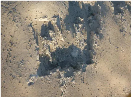
Figure 7. Typical aerial photograph of one part of the quarries.
contained within the image was 0.035m x 60m / 0.028m = 75 meters wide. With an image resolution of 4000 x 3000 pixels, the minimum ground resolution of one pixel can be estimated to be 75m / 4000 = 0.019 meters. Most images however will not have been taken at that altitude but somewhere between 30 to 50 meters. At that altitude the ground resolution will have almost doubled to approximately 1 cm. per pixel.
5.2 Ground Control Points and Accuracy
With the estimated ground resolution of the imagery between 1 and 2 cm. the accuracy of the ground control points (gcp’s) optimally will have to be half of that. The topometric instrument available to us at the time of fieldwork was a total station of the type Topcon GTS-601C, with kind permission of the Centre for Nabataean Archaeology at the Al-Hussein bin Talal University of Ma’an. Through a local calibration of the instrument1 it was found that the used total station setup was able to deliver an accuracy of 1 to 2 cm. depending mainly on wind conditions.
Ideally, the uncertainty of the measurements should be in the range of 0.5 to 1 cm. but this would require either a different setup of the topometric measurements or extensive post-processing of the measurements. Since the main focus of this research was the suitability of the platform and establishing a workflow according to it, it was decided that the current accuracy of the measurements would suffice for the time
1 A calibration following the ISO 17123-5:2005 procedures
for Electronic Tacheometers, executed by R. Emaus.
being. Improving the quality of the gcp’s in a later stage of the research.
5.3 Image Processing
All imagery was processed with the Agisoft PhotoScan software to produce a point cloud and surface model of the site. The software utilises a Structure from Motion algorithm and the individual steps of the processing are already described elsewhere (e.g. Verhoeven, 2011). Although, some of the imagery from the kite did need some specific processing steps. Because of the camera shooting in automatic mode and the obliqueness (ω-pivot) of some of the imagery due to the wind, some images could not be used fully. A rather large aperture sometimes caused parts of some images to be out of focus while the main object in the picture was still in focus. The out of focus part of the picture could easily be omitted by the algorithm by using the mask-function within the PhotoScan software. The object in focus will then still be used to render the 3D point cloud and surface while the out of focus part of the image doesn’t disturb the processing at all. By using the masking function of PhotoScan, more imagery could be used more easily to eventually create a realistic point cloud and surface model of the quarries.
5.4 Model Accuracy Estimation
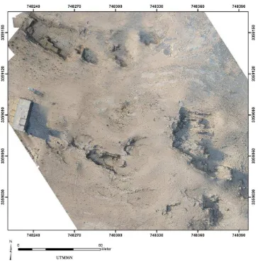
Figure 8. Georeferenced orthophoto of a part of the quarries as created with the surface model and imagery from the kite.
Figure 9. A rendering of the created DEM of a part of the quarries.
reliability will improve with more gcp’s used. When using 4 gcp’s with an equal distribution over the model, a model accuracy of 1.1 cm. is calculated. This means that according to the software a high resolution surface model of the Roman quarries can now be created with a more than satisfactory accuracy.
6. CONCLUSIONS AND FUTURE WORK
The equipment and workflow as described above have proven to be able to deliver a good quality and high resolution surface model of an archaeological site showing a complex morphology (Figure 8 & 9). Since this was a feasibility study of the equipment and workflow, there is some room for improvement.
First, the workflow can be improved through the various wi-fi technologies that enable a direct link with the camera from the ground. As stated, this will reduce the time in the air because of the greater efficiency with which the imagery is taken but also because of not having to shoot in automatic mode. A direct link between the camera and the operator is therefore recommendable. Recent advances in radio but certainly low-cost and mobile wi-fi technology that are already integrated in most camera's these days will help create these optimal working conditions and workflow. When operating the camera through a direct link, a second person is probably required to operate the camera.
Second, although it was possible to create good results using the simple Panasonic camera, the results will improve significantly by using a better camera. With a full-frame camera and standard lens the image quality will improve significantly; improving the resulting DEM accordingly. Third, the accompanying total station survey that provided the gcp’s will have to be improved. Certainly when having a ground resolution of less than 2 cm. a standard total station survey will no longer suffice in most cases. The accuracy of measurement will have to be improved a good deal by using reflectors on fixed mounts instead of human hold reflectors. Also, numerical post-processing of the measurements can reduce the uncertainty to millimetre levels.
Using low-cost equipment, a complex archaeological site was recorded in 3D with an accuracy of almost 1 cm. The final product couldn't have been created with only a total station survey in the same amount of time and with the same amount of detail that the above described setup has made possible. With some further recommendations made on the camera and workflow not only the eventual surface model of the site will be improved significantly, also the amount of time spent in the air will be reduced as well.
ACKNOWLEDGEMENTS
The research would not have been possible without the support of the Udhruh Archaeological Project and the support of the Faculty of Archaeology and Tourism of the Al-Hussein bin Talal University of Ma’an. We would like to thank the directors of the Udhruh Archaeological Project, Mark Driessen and Fawzi Abudanah and its members for their support in the field.
REFERENCES
Aber, J.S., Aber, S.W., Pavri, F., 2002. Unmanned small-format aerial photography from kites for acquiring large-scale, high-resolution, multiview-angle imagery. In: Morain, S., Budge, A. (ed.) Proceedings of the XXIVth ISPRS congress: Commission I. Denver: ISPRS.
Abudanah, F., 2006. Settlement Patterns and Military Organisation in the Region of Udhruh (southern Jordan) in the Roman and Byzantine Periods. Newcastle: University of Newcastle.
Driessen, M.J., Abudanah, F., 2013. The Udhruh Lines of Sight: Connectivity in the Hinterland of Petra. Tijdschrift Mediterrane Archeologie, 50, 45-52.
Hendrickx, M., Gheyle, W., Bonne, J., Bourgeois, J., De Wulf, A., Goossens, R., 2011. The use of stereoscopic images taken from a microdrone for the documentation of heritage: an example from the Tuekta burial mounds in the Russian Altay. Journal of Archaeological Science, 38 (11), 2968-2978.
Kennedy, D.L., 2004. The Roman army in Jordan. London: Council for British Research in the Levant.
Kherfan, A.M., 1998. Geological Map of Bir Khidad 3150 IV. Hashemite Kingdom of Jordan Natural Resources Authority, Geology Directorate, Geological Mapping Division. Amman: The Royal Jordanian Geographical Centre.
Killick, A.C., 1983. Udhruh. The Frontier of an Empire: the 1980 and 1981 seasons, a preliminary report. Levant, 15, 110 – 131.
Verhoeven, G.J.J., 2009. Providing an archaeological bird's-eye view: an overall picture of groundbased means to execute low-altitude aerial photography (laap) in archaeology. Archaeological Prospection, 16, 233 – 249.
Verhoeven, G.J.J., 2011. Taking Computer Vision Aloft – Archaeological Three-dimensional Reconstructions from Aerial Photographs with PhotoScan. Archaeological Prospection, 18, 67-73.
Verhoeven, G.J.J., Loenders, J., Vermeulen, F., Docter, R., 2009. Helikite aerial photography: a versatile means of unmanned, radio controlled, low-altitude aerial archaeology. Archaeological Prospection, 16, 125 – 138.