Adaptive Cars Headlamps System
with Image Processing and Lighting
Angle Control
William Tandy Prasetyo, Petrus Santoso and Resmana Lim
Abstract The project proposed a prototype of an adaptive car headlamps control using image processing. The adaptive headlamps system focuses on the lighting angle control of low beam in the headlamps which its light tracks moved hori-zontally. The controller in headlamps is based on image processing from a camera mounted on the car. Adaptive headlamps system consists of portable tiny computer of Raspberry Pi, Arduino microcontroller, and two stepper motors for the left and the right headlamps. The system was implemented on the headlamps of a Toyota Avanza car. The adaptive headlamps system could detect most types of cars ahead. It could decrease a‘glare’effect and increase the driver sight based on survey taken
from the driver and the driver of opposite car. The system still couldn’t detect the
opposite car with high intensity of light from braking lamps, as well as the light from the opposite front lamps.
Keywords Adaptive cars headlamps
ArduinoImage processingRaspberry pi45.1
Introduction
Night is the time when vehicle accidents often occurred [1]. The causes can be various such as the headlamps light in the car aren’t focused or the lights intensity
are too low or the lights make glared (dazzled) effect for other car drivers [2]. On the other side, technology for controlling headlamps light were rarely found these years. Nowadays, most of researches often focus on car speed controller research (cruise control), and automatic car parking system. The need of headlamps tech-nology is important based on the facts above.
Several companies have produced and sold their headlamps technology products to the market. Hella, one of the automotive company sold their headlamps
W.T. Prasetyo (&)P. SantosoR. Lim
Electrical Engineering Department, Petra Christian University, Surabaya, Indonesia e-mail: [email protected]
©Springer Science+Business Media Singapore 2016
F. Pasila et al. (eds.),Proceedings of Second International Conference on Electrical Systems, Technology and Information 2015 (ICESTI 2015), Lecture Notes in Electrical Engineering 365, DOI 10.1007/978-981-287-988-2_45
technology product called“Adaptive Front-light System (AFS)”that can control the
headlamps light based on car steering [3]. The AFS technology also proposed in [4]. Valeo company also provided their product“Light/on&off”that can switch the
headlamps light on and off automatically based on light intensity around the car [5]. The headlamp technology that used by Valeo, also similar with Stein’s project [6].
Those two above still can’t reduce the dazzled (glared) effect for other cars.
This paper offers headlamps technology that can overcome the problems above. Headlamps technology in this paper can control headlamps light’s track adaptively
based on object detection (car’s back side) data. The headlamps light’s track can
move horizontally based on position of the object.
45.2
Adaptive Headlamps System Set-up
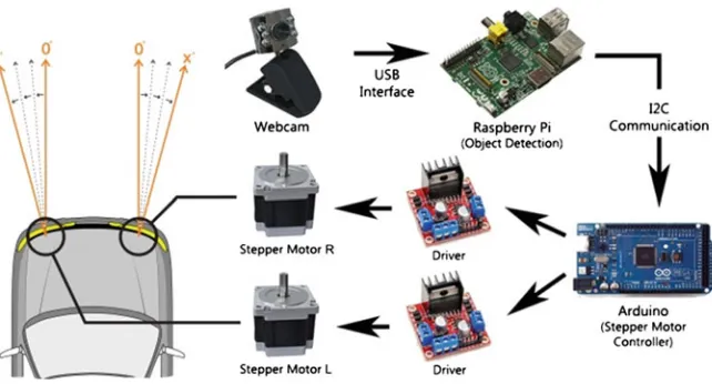
This section provides the outline of the adaptive headlamps controller system. The block diagram of the system displayed on Fig.45.1.
There are two primary processes in the Fig.45.1such as object detection process on raspberry pi and stepper motor controller on arduino. Raspberry pi communi-cates with webcam through USB (Universal Serial Bus) interface. It also does I2C communication through GPIO pins (GPIO 03, GPIO 05) which SDA, and SCL port located on raspberry pi. Arduino as stepper motor controller also do I2C commu-nication through I/O pins (digital pins 20, 21) which SDA, and SCL port located on Arduino. Arduino controls two stepper motors through L298N motor drivers which can drive them with higher current.
45.3
Design of Adaptive Headlamps
Design of adaptive headlamps is divided into two parts, which are hardware and software. Hardware part consists of the design of headlamp itself, and installation of the controller, including installation of the webcam. The software design consists of Raspberry Pi’s software design and Arduino’s software design.
45.3.1
Hardware Design
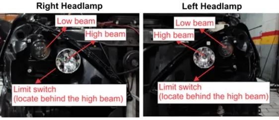
Headlamps that used in this paper are Toyota Avanza 2009 car’s headlamps with
projector lens. The headlamps were modified by adding limit switch behind the high beam lamp. It is used to limit the movement of the lamp and set the position of the stepper motor into zero position (Fig.45.2).
Adaptive headlamps controller consists of one Raspberry Pi B tiny portable computer, one driverless webcam, one arduino mega R3 2560 microcontroller, two pieces of L298N motor driver, 12 V regulator to stabilize the voltage from car battery, and toggle switch for auto-manual control. There are also keyboard and mouse attached on Raspberry Pi for user interface. All of the components mounted on a board, then placed below left-front dashboard of the car. The webcam is installed inside of the car, and the position is on the middle of the car, and the height about half of car height, so its position in line with the detected object. The position of the adaptive headlamps controller board and webcam displayed in Fig.45.3.
45.3.2
Raspberry Pi
’
s Software Design
Raspberry Pi’s software design is divided into four points which are object
detection, headlamps light track movement calculation, I2C communication, and manual control program. Raspberry Pi uses Raspbian operating system based on Linux kernel. Python is used to create the program and OpenCV library is used as compiler for image processing in the Raspberry Pi.
The program code starts with object detection by the webcam. Webcam captured the object by creating a ROI (Region of Interest) in window screen marked by blue rectangle when the object is correct and in range of detection. Webcam used 320 × 240 pixel resolution due to low specification of the Raspberry Pi. Low
resolution of webcam makes the Raspberry Pi works faster but as the compensation the image quality become lower. Object detection in Raspberry Pi used OpenCV library by importing“cv2”library in the program and used“cascade.xml”file that
contain the trained data. Trained data were obtained by doing haar training on hundred images of cars.Haartraining that used in this paper based on Viola-Jones paper which provides faster face detection usinghaartrained data [7].
Headlamps light track movement calculation starts from the distance calculation then calculate the position where the stepper motors will stop. Triangle similarity is used to calculate the distance from webcam to the object [8]. Triangle similarity equation shown as below:
F¼ðPxDÞ=W ð45:1Þ
where F is focal length of webcam, P is object length in webcam (pixel), D is the distance (cm), and W is object length in real (cm). This equation used tofind the focal length of the camera, so all of the parameters except F should be knownfirst
by manual measuring. Then triangle similarity equation used again in different way in program. The equation shown as below:
D0¼WxF=P0 ð45:2Þ
where W is object length in real (cm) same as before, F is focal length obtained from Eq. (45.1), P’is object length in webcam (pixel) and D’is the distance (cm).
P’ obtained by measuring the length of ROI rectangle that represents the object
length in webcam and D’is the distance that used to determine the position where
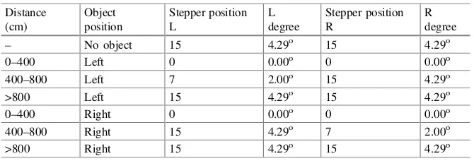
the stepper motor stopped. List of positions based on distance between webcam and detected object are shown at Table45.1.
Numbers in stepper position L/R columns mean the position of rotation of stepper motor at that time, for example, number 7 means the stepper motor rotates 360° 7 times and stops at that position. Position number of stepper motors that
determined from the list are sent to the Arduino through I2C port.
The manual control program designed for users so the users can move the headlamps light track movement manually. Users can give input“1, 2, 3 and 4”to
the Raspberry Pi using keyboard to rotate stepper motors 180° clockwise or
counter-clockwise. Left stepper motor is controlled by“1 and 2”input and the right
side is controlled by“3 and 4”input, then the input sent to Arduino.
45.3.3
Arduino
’
s Software Design
Arduino’s software design is divided into three points such as automatic control
(adaptive) of headlamps light track movement, manual control and I2C commu-nication. Arduino IDE is used to design the program.
Automatic and manual control of headlamps light track movement program receive stepper motors position data from Raspberry Pi through I2C port. Automatic control’s program in Arduino converts the position data so it can rotate
the stepper motors precisely. Before automatic control program executed, the calibration program is run and rotates the stepper motors to move at zero position. Manual control of headlamps light track movement program also converts the position data from Raspberry Pi to rotate the stepper motors based on users input. Program for automatic and manual control switch also configured in this software design.
45.4
Results and Discussions
The system test has been done at night on the road which has been‘conditioned’for
avoiding undesired incidents and safety. This system test consists of pictures which show webcam pictures results, and driver sights whether from the car with adaptive headlamps attached or the opposite car. Conditions on this system test was divided into three conditions based on the object condition. The first condition was the driver in opposite car didn’t push the brake pad, the second condition was the driver
in opposite car pushed the brake pad, and the third, the position of opposite car was face to face with the car. Distance between car and the opposite car was approxi-mately 4–8 m and the position of opposite car was at the left side of the car. The
opposite car that used in this system test was Honda Brio 2014.
Table45.2shows the pictures results of webcam detection that can only detect object when the condition of the opposite car’s driver didn’t push the brake pad. It
happened because the light intensity was too high for the webcam so webcam couldn’t detect the object properly.
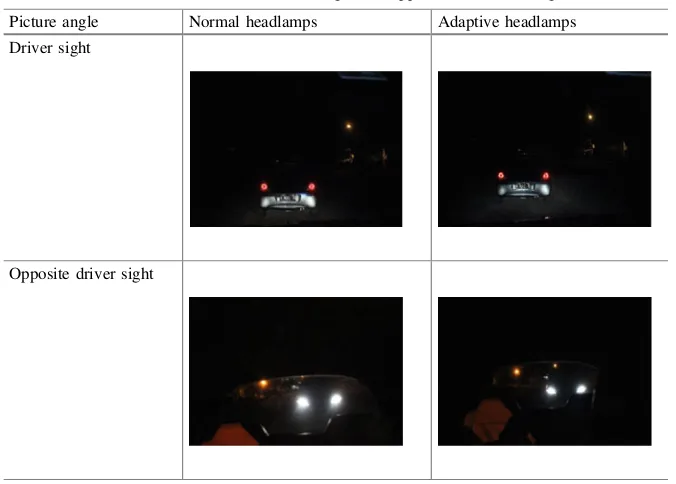
System test on the driver sight has been done by taking pictures using DSLR camera with the same settings. The pictures consist of four pictures with different angles. Thefirst and second took from the car driver sight with normal headlamps and adaptive headlamps. The third and fourth took from the opposite car driver
Table 45.2 Pictures results of webcam detection based on object conditions Object car was face to face with the car
Detection results in webcam
sight with normal headlamps and adaptive headlamps. The condition of the opposite car was the same condition as thefirst condition in the system test before. The light track of normal and adaptive headlamps on driver sight look different on Table45.3. The light track on adaptive headlamps seems wider than the normal. The dazzled (glared) effect from opposite car also reduced at the adaptive head-lamps pictures (the light intensity was lower than the normal).
45.5
Conclusion
The system test result shown that adaptive headlamps can increase the driver sight and decrease the dazzled (glared) effect on the opposite car side. The object detection also could run properly on the condition when the light intensity from the opposite lamps weren’t too high for the webcam. In the future, there will be several
improvements that can be applied with this paper for example improvement on webcam which can detect lights with higher intensity.
Table 45.3 Pictures results from car’s driver sight and opposite car’s driver sight
Picture angle Normal headlamps Adaptive headlamps
Driver sight
References
1. Apriliananda, D.: Ini Waktu Rawan Kecelakaan Lalu Lintas! 11 September 2014. http:// otomotif.kompas.com/read/2013/12/24/1935538/Ini.Waktu.Rawan.Kecelakaan.Lalu.Lintas 2. Kompasiana, 85% Kecelakaan Lalu-lintas Karena Human Error. 28 December 2011
(10 November 2014). http://lifestyle.kompasiana.com/catatan/2011/12/28/85-kecelakaan-lalu-lintas-karena-human-error-422758.html
3. Hella, Adaptive Frontlight System (AFS). 14 June 2012. 10 September 2014. http://www. youtube.com/watch?v=Cu_0G9QtAMo
4. light/on&off™, Automatic Car Headlight, Lights, Automatic Car Lighting System. t.thn. 11 September 2014. http://www.smileyouaredriving.com/uk_en-products.driving-assistance. video-7.html
5. Antony, B., Manoj, M.: Control algorithm for adaptive front light systems. Int. J. Comput. Trends Technol.9(7), 339–343 (2014)
6. Stein, G.P., et al: Headlight, Taillight and Streetlight Detection. United States Patent (2009) 7. Open CV-Python Tutorials. Face Detection using Haar Cascades (2015)