WELCOME MESSAGE
CONFERENCE ORGANIZATION
LIST OF PAPERS
KEYNOTE
Impact of Electromagnetic Fields on Current Ratings
and Cable Systems
H. Orton (Convener) (Canada); P. Maioli (Secretary) (Italy),
H. Brakelmann (Germany); J. Bremnes (Norway); F. Lesur (France);
J. Orella Saenz (Spain); J. Smit (The Netherlands)
ID 12
Design of Snubber Circuit and PI Control to Achieve Load Independent Output
Voltage in Micro Smart Home System
Didi Istardi, Andy Triwinarko
ID 13
Economic Cost Study of Photovoltaic Solar System for Hotel in Nusa
Lembongan
I.A.D. Giriantari, I.N.S. Kumara, D.A. Santiari
ID 14
Elimination of Sympathetic Inrush Currents in Transformers Connected in
Parallel
Kartik P Basu, Naeem M Hanoon
ID 18
Investigation and Modelling of Sympathetic Inrush Due to Transformer
Energization
LIST OF PAPERS
ID 19
Load Fl
ow and Supply Security Analysis of Power System in Tiga Nusa;
Before and After the Application of 20kV Submarine Cable
Dayu Giriantari, I W. Sukerayasa, Y.M.A. Prawira
ID 20
The Design of Web Based Academic Information System in Universitas Sains
dan Teknologi Jayapura
Marla S.S. Pieter, Evanita V. Manullang
ID 21
Implementation Dedicated Sensing Receiver (DSR) in 3G - WiFi Offload
Setiyo Budiyanto, Muhammad Asvial, Dadang Gunawan
ID 22
Website Content Management Analysis of eGovernment in Bali Province
According to the Ministry of Communications and Information Guide (KOMINFO)
Gerson Feoh, Linawati, Ni Made Ary Esta Dewi Wirastuti
ID 23
Server Log Monitoring Based On Running Services
ID 31
Performance Analysis of Packet Scheduling Algorithm for Video Service in
Downlink LTE
Ida Nurcahyani, I Wayan Mustika, and Selo
ID 35
Study on Feasible Solution of Power Control in Cognitive Radio Networks
Norma Amalia, I Wayan Mustika, and Selo
ID 42
Visualization of Indonesian Translation of Quran Index
Suwanto Raharjo, Khabib Mustofa
ID 43
A Review : Identification of Avian Influenza Environmental Risk Factor using
Remote Sensing Image and GIS
M. A. Padmasari, Linawati, N.M.A.E.D. Wirastuti
ID 44
Modelling and Numerical Simulation of Multiple One Way Gears Wave Energy
Converter to Generate Electricity
LIST OF PAPERS
ID 61
Comparison between RC Detector and High Frequency Current Transformer in
Measuring Partial Discharge in Liquid Insulation
Suwarno, Aulia
ID 62
Unidirectional Motion Estimation Technique With Full Search Algorithm For Frame
Rate Up-Conversion Video
Widya Yuniari, Oka Widyantara, Linawati
ID 63
Modeling and Detection of High Impedance Faults
Huwei Wu, B.T. Phung, Daming Zhang, Jichao Chen
ID 75
Effect of the Distance of Partial Discharge Sensor to Partial Discharge Source on
the Attenuation of Partial Discharge induced Electromagnetic Wave in Gas Insulated
Switchgear
Umar Khayam, Zahrina Hafizhah
ID 77
New Designed Bowtie Antenna with Middle Sliced Modification as UHF Sensor for
Partial Discharge Measurement
ID 78
Demand and Thermal Aware Approach for Greener IaaS-Cloud Data-Centers
Nazi Tabatabaei Yazdi, Chan Huah Yong
ID 85
DC Motor Speed Control with Pulse Width Modulation (PWM) Method of Infrared
Remote Control Base on Microcontroller ATmega16
Putu Raka Agung, Syamsul Huda, I Wayan Arta Wijaya
ID 86
Microhydro Powerplant for Rural Area in Bali to Generate Green and Sustainable
Electricity
DC Motor Speed Control with Pulse Width
Modulation (PWM) Method of Infrared Remote
Control Base on ATmega16 Microcontroller
I Gst. Ag. Putu Raka Agung1), Syamsul Huda2), I Wyn Arta Wijaya3)
1,2,3)
Department of Electrical Engineering, University of Udayana Bukit Jimbaran, Bali, Indonesia
E-mail: 1)[email protected]
Abstract— It is very important task to control the speed of direct
current (DC) motor for various applications. In particular requirement, setting a speed DC motor as the driving equipment must be performed remotely. Under that condition, conducted a research on a DC motor speed control with pulse width modulation (PWM) method of the infrared remote control. PWM is method that may be used as a efficient DC motor speed control. Controller used TV remote control to send data to ATmega16 microcontroller through the IR receiver. This command controls the IC driver L293D to control the direction and speed of a DC motor. To calculate the speed of a DC motor, used perforated disk attached to the motor shaft is placed between the photodiode and the LED as a sensor. Research results obtained are the direction and speed of a DC motor can be set from the infrared remote control with PWM method using ATmega16 microcontroller. Furthermore, the results of these settings can be displayed on the LCD repeated every 7 seconds.
Keywords—dc motor; remote control; PWM; microcontroller
I. INTRODUCTION
Advances in technology led to the role of humans being replaced by machines or automatic control devices to do some job. One another device in automatic control is motor. Motor is device that converts electrical energy into mechanical energy. The motor that utilizes a DC supply to produce mechanical output is direct current (DC ) motor. Direct current (DC) motors have been widely used in many industrial applications such as electric vehicles, steel rolling mills, electric cranes, and robotic manipulators due to precise, wide, simple, and continuous control characteristics [1].
The motor speed can be controlled by controlling armature voltage and armature current. These method have some demerit because some power is wasted in control resistance. PWM method also can be used to control dc motor speed. PWM circuit work by making a square wave with a variable on to off ratio. The ratio can vary between 0 % - 100%. In this manner variable power is transferred to load. Main advantage PWM circuit over a resistive power control is the efficiency[2]. On PWM 50% amount off pulse and on pulse is equal.
Remote control can be used to control devices in long distance through infrared (IR) medium. Each keys on remote control have different code. The different code can be convert to be hexa digital data with IR receiver (TSOP1736)[3].
and processed in microcontroller. Output data of microcontroller are on off pulsed to rotate DC motor.
II. DESIGN 2.1 Hardware Design
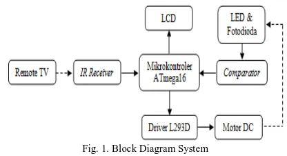
The block diagram of a DC motor speed control system in this research can be seen in Figure. 1.
Fig. 1. Block Diagram System
TV remote control function sends data at infrared wavelengths to the infrared receiver . Data received in the form of pulses were delivered to the INT1 pin ( PD3 ) microcontroller to read bit by bit data, in order to obtain different data on each key is pressed.
The results of the data translation remote control key are used by the microcontroller to control the speed of a DC motor via the IC driver L293D. Where the - key to set the motor rotates to the left , the + key to set the motor rotates to the right , keys 1 , 2 , 3 , 4 , 5 , 6 , 7 , 8 , 9 , and 0 to set the motor speed according to the duty cycle program has been set in the PWM, and the SLEEP key to stop the motor rotation .
The output of the photodiode still analog form so that the analog comparator is added to convert it to digital form. Logic 1 (High) pulse output when the light from the LED passes through the hole in the disc , and logic 0 (Low) pulse output when the light from the LED is blocked by the disc. The digital data is then sent to the INT0 pin microcontroller to be processed in order to obtain a DC motor speed in rpm units. The result of setting a DC motor direction and speed will be displayed on the LCD on port C ( PC2 - PC7 ) repeated every 7 seconds .
2.1.1 Power Supply Circuit
The power supply is needed in this research is to supply +12 V and +5 V on DC motor, microcontroller ATmega16, IC TSOP1736, IC L293D, LCD, and speed sensor. Power supply circuit can be seen in Figure. 2.
Fig. 2. Power supply circuit
2.1.2 Minimum System ATmega16 Microcontroller Circuit[4] Minimum system using 11.0592 MHz crystal oscillator. Port D is used as data input infrared signal through pin INT1 and speed sensor DC motor rotation through INT0 pin. Port B is used as a microcontroller to adjust the output IC driver L293D, and port C is used as input and output data to the LCD. Minimum system circuits ATmega16 can be seen in Figure 3.
Fig. 3. System minimum ATmega 16 microcontroller circuit
2.1.3 LCD Circuit[5]
LCD pins are connected to the ATmega16 microconroller ports are DB4 - DB7 with PC4 - PC7, enable pin with PC3, RS pin with PC2 and R/W pin is connected to GND. Contrast LCD pin is connected on 1 KOhm resistor that used as a light background LCD brightness control. Figure. 3 shows the LCD circuit.
Fig. 3. LCD circuit
2.1.4 Infrared Receiver Circuit[3]
Infrared receivers are used in this research is TSOP1736 which consists of 3 pins , the VCC , GND , and outputs. LED
on the VCC is used to detect that data can be received by the
infrared sensor, and LED will flash according to the pulses received . Figure 4 shows infrared receivers circuit.
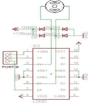
Fig. 4 Infrared receivers circuit 2.1.5 L293D IC circuit[6]
The pins of L293D IC are connected to ATmega16 port are Enable1-2 (1-2EN) to PB2 , IN1 (1A) to PB1, and IN2 (2A) to PB0 , while OUT1 (1Y) and OUT2 (2Y) pins is connected to DC motor terminals. Figure. 5 shows the L293D IC circuit.
Fig. 5. L293D IC circuit
-109-2.1.6 DC Motor Speed Sensors Circuit
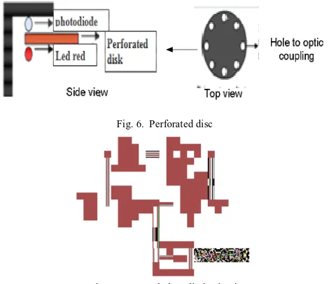
To be able to read the speed of DC motor, added a perforated disc mounted to the shaft of the DC motor as shown in Fig. 6. Disc around a hole as much as 8 so light LED can pass through the hole on the photodiode. The disc is placed between the LED and the photodiode . If photodiode get light from the LED, photodiode output to be logic 1 (high ) . If the LED light does not hit the photodiode thus output to be logic 0 (low ). LED and photodiode circuits shown in Figure 6. How times photodiode logic 1 within a period of minute , the result is divided by 8 ( number of holes ) would be associated with a DC motor speed in rpm units. LED and photodioda circuit can be seen on figure 7.
Fig. 6. Perforated disc
Fig. 7. LED and photodiode circuit
2.1.7 Sony SIRC Protocol
The remote control is used to provide data to an infrared receiver as motor controllers in this research is the Sony TV remote control. Sony remote control protocol uses pulse width encoding of bits. Pulse width representing a logic 1 has a length of 1.2 ms with a carrier of 40 kHz, while the width of the pulse to a logic 0 is 0.6 ms. All high spikes separated by intervals of space with a pulse length of 0.6 ms. [7]
2.2 Software Design
Microcontroller ATmega16 programing in this research using basic language, namely the Bascom. Flow diagram program DC motor speed control in this research can be seen in Figure 8.
Fig. 8. Flow diagram DC motor speed control program
III. RESULTS AND DISCUSSION 3.1 Actual Tools
Realization tool made in this research can be seen in Figure 9.
Fig. 9. Result of design hadware
3.2 Testing and analisys
Testing a DC motor speed control system is done by measuring parameters directly at the time of the experiment . Testing parameters include:
3.2.1 Power supply circuit
Testing is done using digital avometer by measuring voltage 12 V DC motor and the supply voltage of 5 V as Vcc. The measurement results can be seen in Table 1.
Table 1. Results of Testing the Power Supply
No Node Voltage
1 Supply DC Motor 11.97 V
2 Vcc 4.98 V
The results in Table 1 indicate that the power supply is functioning properly because the voltage generated is sufficient to supply the DC motor and digital electronic components .
3.2.2 Minimum System ATmega16 Circuit
Measurements were taken at one of the port A by measuring logic high and logic low voltage port. The measurement results can be seen in Table 2.
Table 2. Results of testing Minimum System ATmega16 No Condition Port A
1 High 4.95 V
2 Low 0.00 V
The results in Table 2 show that voltage range of minimum system ATmega16 have function as expected
3.2.3 LCD Circuit
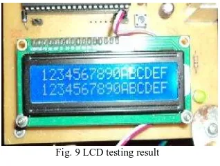
Testing was conducted to determine whether the LCD was able to function properly, so it can display the data as expected. Testing is done with a simple program to display the text " 1234567890ABCDEF " on LCD line 1 and 2 , the results can be seen in Fig. 9. The results in Fig. 9 show that the LCD can display characters properly in accordance with the program.
Fig. 9 LCD testing result
3.2.4 Infrared Receiver Circuit
Infrared receiver tests is performed to prove that the sensor can perform well data readout, and programs provided to read remote control data has the appropriate. The test results can be seen in Table 3.
Table 3. Result of testing Remote Control data key
Key data Key data
1 128 8 135
2 129 9 136
3 130 0 137
4 131 + 244
5 132 - 245
6 133 SLEEP 182
7 134
The results in Table 3 indicate that the circuit (hardware) and program (software) to read the data of the infrared remote control receiver is correct .
3.2.5 L293D Driver Circuit[6]
The purpose of this measurement is to measure value on the input voltage IC L293D motor speed varying conditions . The test results can be seen in Table 4.
Table 4 Results of Testing IC L293D
No Test conditions
1,2EN IN1 IN2
1 Right rotate 4.98V 4.98V 0.01V 2 Left rotate 4.98V 0.01V 4.98V 3 Stop 0.01V 4.98V 4.98V
The results in Table 4 show that the L293D IC driver is functioning properly in accordance with the truth table IC L293D.
3.2.6 Motor Speed Sensor Circuit
Testing was conducted to determine whether the sensor circuit can read the motor rotation speed . The test results can be seen in Table 5.
Table 5. Results of Testing Speed Sensor No Test
condition
Vin Vref Vout
1 High 4.95V 4.55V 1.73V
2 Low 0.17V 4.55V 4.95V
The results in Table 5 show that the photodiode sensor and comparator can already read motor rotation well because it could send. a highs and lows signal to the microcontroller 3.2.7 Overall testing
Tests conducted to determine the performance of a tool that has been designed and programmed in accordance with a predetermined function . The test results obtained as shown in Table 6.
Table 6. Results of Testing In Overall
No key PWM
(%)
speed (rpm)
Voltage (V)
1 1 10 48 2.02
2 2 20 72 3.00
3 3 30 96 3.89
4 4 40 114 4.76
5 5 50 140 5.70
6 6 60 165 6.67
7 7 70 192 7.75
8 8 80 224 8.97
9 9 90 261 10.34
10 0 100 294 11.67
11 SLEEP 0 0 0
Overall test data in Table 6 indicate that the data on the remote control key is pressed is in conformity with the PWM setup program that has been determined . Relationship PWM
-111-and voltage to the motor speed -111-and PWM showed that a voltage value is proportional to the rotation speed of DC motor is generated. The greater the PWM , the motor voltage ( terminal voltage ) will also increase so that the motor will rotate faster .
IV. Conclusion
Conclusion of this research are as following:
1. Direction and rotation speed of a DC motor can be controlled with PWM method by infrared remote control base on ATmega16 microcontroller.
2. The relationship between PWM and terminals voltage with a rotation speed of the motor is directly proportional. The greater the PWM, the terminal voltage will also increase so that the motor will rotate faster .
References
[1] Moleykutty George. Speed Control of Separately Excited DC Motor, American Journal of Applied Sciences 5, 2008 Science Publications [2] Anonymous , Speed and Direction Control of DC motor Using PIC
Microcontroller Using PWM and H-Bridge. Available
http://wineyard.in/wp-content/uploads/2011/12/WK605.pdf accessed on Oct 10, 2014
[3] Vishay . Photo Modules for PCM Remote Control Systems . http: //svn.clifford.at/metaparts/trunk/atasheets/DS_c270180d65055cebc26d 49a51fae1ca6.pdf 2001 . Accessed on May 10, 2013 .
[4] ATMEL . ATmega16 , ATmega16L . 2010. Available http: //www.atmel.com/Images/doc2466.pdf . Accessed on May 10, 2013 [5] Anonymous . PC1602A - L ( 16x2 ) Character Display LCD. Available
http://www.geniusnet.sk/om3bc/datasheets/PC1602Series.pdf 2004 . Accessed on May 17, 2013.
[6] Texas Instruments . L293 , L293D Quadupler Half - H Drivers . Available http://www.datasheetcatalog.org/datasheet/texasinstruments/ l293d.pdf 2002 . Accessed on May 10, 2013 .
[7] Anonimous. Sony SIRC infrared protocol. 2010. Available http://picprojects.org.uk/projects/sirc/sonysirc.pdf. Accesed on May 17, 2013