ABSTRAK
Perkembangan teknologi yang semakin pesat, menuntut suatu industri dapat
menyediakan berbagai tingkat kebutuhan konsumen yang beraneka ragam dengan efisien
tanpa menurunkan mutu produksi. Untuk itu, diperlukan standar pengukuran untuk
menentukan karakteristik suatu produk yang sesuai.
Dalam Tugas Akhir ini akan dibahas mengenai alat ukur yang dapat menentukan
nilai Tensile dan keelastisitasan plastik. Tensile adalah gaya maksimum yang dapat
diberikan pada suatu plastik sebelum plastik itu putus. Alat ukur ini digerakkan oleh
motor DC dengan menggunakan pengontrol berupa Mikrokontroler. Sedangkan untuk
proses analisa matematisnya dilakukan di dalam komputer dengan menggunakan
program Borland Delphi.
Alat ukur ini menggunakan dua buah sensor yaitu sensor strain gauge dan sensor
optocoupler. Sensor strain gauge berfungsi sebagai sensor tekanan yang mempunyai output berupa tahanan. Dengan menggunakan regresi polinomial, tahanan tersebut kemudian akan dikonversikan ke tegangan untuk mendapatkan nilai gaya. Sedangkan
optocoupler berfungsi untuk menentukan besarnya perubahan panjang plastik.
Dalam percobaan digunakan dua buah jenis plastik yaitu Natural V 100 dan
Thermacell. Nilai Tensile untuk plastik jenis Natural V 100 adalah 0,628 MPa dengan
elastisitas 0,508 MPa. Tingkat keberhasilan Tensile untuk plastik jenis ini adalah 82,2 %
dengan elastisitas 83,8 %. Untuk plastik jenis Thermacell didapat nilai Tensile 0,59 MPa
dengan elastisitas 0,569 MPa. Tingkat keberhasilan Tensile untuk plastik jenis ini adalah
80,2 % dengan elastisitas 80,5 %. Plastik dengan jenis Natural V 100 memiliki nilai
ABSTRACT
The fast developing in technology has made an industry to be able to provide the
various level of demands effectively. For that, it is required a measurement standard for
determining the productâs character properly.
In this Final Project the measurement device which can determine the Tensile
value and plastic elongation will be discuss. The Tensile is the maximum force which can
be given to plastic before it is cut off. This measurement device is moved by DC motor
with using microcontroller, in the meantime the process of mathematic analyze is done by
computer by using Borland Delphi software.
This measurement device uses two sensors, namely, the strain gauge sensor and
optocoupler sensor. Strain gauge is used as a pressure sensor which has resistance output.
With using polynomial regression, the resistance will be converted to tension to get the
force point. On the other hand, the optocoupler has a function to determine the changes of
plastic length.
In this experiment, two plastics like Natural V 100 and Thermacell are use.
Tensile value for Natural V 100 plastic is 0,628 MPa with elongation is 0,508 MPa, the
successful level of Tensile is 82,2 % and elongation is 83,3 %. For the Thermacell
plastic, tensile value is 0,59 MPa with elongation is 0,569 MPa, the successful level of
Tensile is 80,2 % and elongation is 80,5 %. From the experiment, the Tensile value and
elongation of Natural V 100 is bigger than Thermacell. The characteristic of matter
DAFTAR ISI
LEMBAR PENGESAHAN
SURAT PERNYATAAN
ABSTRAKâ¦â¦â¦.. i
ABSTRACT... ii
KATA PENGANTARâ¦â¦â¦ iii
DAFTAR ISIâ¦â¦â¦... v
DAFTAR GAMBARâ¦â¦â¦. viii
DAFTAR TABELâ¦â¦â¦.. ix
DAFTAR PERSAMAANâ¦â¦â¦... x
DAFTAR LAMPIRANâ¦â¦â¦... xii
I. PENDAHULUAN I.1 Latar Belakangâ¦â¦â¦ 1
I.2 Identifikasi Masalahâ¦â¦â¦ 1
I.3 Tujuanâ¦â¦â¦. 1
I.4 Pembatasan Masalahâ¦â¦â¦... 1
I.5 Spesifikasi Alatâ¦â¦â¦... 2
I.6 Sistematika Penulisanâ¦â¦â¦.. 2
II. TEORI PENUNJANG II.1 Elastisitas, Stress dan Strain â¦â¦â¦.. 3
II.1.1 Elastisitasâ¦â¦â¦.. 3
II.1.2 Stress dan Strainâ¦â¦â¦... 5
II.2 Standar ASTM D 638-80â¦â¦â¦... 6
II.3 Mikrokontroler AT89C51â¦â¦â¦... 7
II.3.1 Arsitektur Mikrokontroler AT89C51â¦â¦â¦... 7
II.3.3 Fungsi-Fungsi Pin MCU AT89C51â¦â¦â¦. 9
II.3.4 Organisasi Memoriâ¦â¦â¦.. 10
II.3.4.1 Memori Program... 11
II.3.4.2 Memori Dataâ¦â¦â¦. 12
II.3.5 Interupsi â¦â¦â¦.. 12
II.4 Analog to Digital Converter (ADC)â¦â¦â¦.. 13
II.5 Rangkaian Jembatan Wheatsone â¦â¦â¦... 15
II.6 Rangkaian Instrumentation Amplifierâ¦â¦â¦ 16
II.7 Sensor â¦â¦â¦... 19
II.7.1 Strain Gauge â¦â¦â¦.. 19
II.7.1.1 Prinsip Strain Gaugeâ¦â¦â¦ 20
II.7.1.2 Karakteristik Aplikasi Strain Gauge... 22
II.7.2 Optocouplerâ¦â¦â¦... 23
III. PERANCANGAN DAN REALISASI III.1 Diagram Blok dan Cara Kerja â¦â¦â¦.. 25
III.2 Perancangan Perangkat Kerasâ¦â¦â¦... 27
III.2.1 Mikrokontroler AT89C51â¦â¦â¦. 27
III.2.2 Analog to Digital Controller (ADC)â¦â¦â¦. 29
III.2.3 Rangkaian Catu Dayaâ¦â¦â¦ 30
III.2.4 Sensor Optocouplerâ¦â¦â¦ 31
III.3 Perancangan Perangkat Lunakâ¦â¦â¦... 32
IV. PENGUJIAN ALAT DAN DATA PENGAMATAN IV.1 Pengukuran Catu Daya... 36
IV.2 Pengukuran Tegangan Pada Sensor Strain Gauge... 37
IV.2.1 Pengukuran Tegangan Pada Sensor Strain Gauge Dengan Menggunakan Instrumentation Amplifier... 37
IV.3 Pengukuran pada Sensor Optocouplerâ¦â¦â¦.. 38
IV.4 Pengukuran Tegangan Output pada Rangkaian Secara Keseluruhan... 39
IV.6 Data Percobaan Tensile dan Elastisitas Plastik Berdasarkan
Perhitungan... 43
IV.7 Analisis... 45
V KESIMPULAN DAN SARAN
V.1 Kesimpulan... 47
V.2 Saran... 47
DAFTAR PUSTAKAâ¦â¦â¦. 48
DAFTAR GAMBAR
Gambar II.1 Hukum Hooke â¦â¦â¦. 3
Gambar II.2 Kurva gaya yang diberikan terhadap pertambahan panjangâ¦â¦â¦... 4
Gambar II.3 Arsitektur MCU ATMEL 89C51â¦â¦â¦ 8
Gambar II.4 Susunan Pin Pada AT89C51â¦â¦â¦... 10
Gambar II.5 Organisasi Memori ATMEL AT89C51 â¦â¦â¦. 11
Gambar II.6 Memori Programâ¦â¦â¦. 11
Gambar II.7 Memori Data Internalâ¦â¦â¦.. 12
Gambar II.8 Pin ADC 8 bitâ¦â¦â¦... 14
Gambar II.9 Rangkaian jembatan Wheatstoneâ¦â¦â¦. 15
Gambar II.10 Rangkaian Instrumentation amplifierâ¦â¦â¦.. 17
Gambar II.11 Rangkaian Instrumentation Amplifier Pada Saat V2 = 0â¦â¦â¦.. 17
Gambar II.12 Rangkaian Instrumentation Amplifier Pada Saat V1 = 0â¦â¦â¦.. 18
Gambar II.13 Rangkaian Differential Amplifierâ¦â¦â¦. 18
Gambar II.14 Sensor Strain Gaugeâ¦â¦â¦. 20
Gambar II.15 Tensile dan compressional stress untuk penerapan pada balokâ¦â¦... 20
Gambar II.16 Diagram blok sensor optocouplerâ¦â¦â¦. 23
Gambar II.17 Rangkaian Fotodiodaâ¦â¦â¦ 23
Gambar III.1 Diagram blok cara kerja sistemâ¦â¦â¦.... 25
Gambar III.2 Alat ukur elastisitas plastikâ¦â¦â¦.. 26
Gambar III.3 Rangkaian Mikrokontroller MCS-51â¦â¦â¦ 28
Gambar III.4 ADC 0804 dalam keadaan free-runningâ¦â¦â¦... 30
Gambar III.5 Rangkaian lengkap catu dayaâ¦â¦â¦ 31
Gambar III.6 Rangkaian Optocouplerâ¦â¦â¦ 32
Gambar III.7 Diagram alir programâ¦â¦â¦ 33
Gambar III.8 Diagram alir proses di komputerâ¦â¦â¦... 34
DAFTAR TABEL
Tabel II.1 Alamat Layanan Rutin Interupsi Persamaan... 13
Tabel III.1 Hubungan port-port pada Mikrokontroler AT89C51â¦â¦â¦.. 27
Tabel IV.1 Hasil Pengukuran Tegangan Keluaran Pada Catu Dayaâ¦â¦â¦ 36
Tabel IV.2 Hasil Pengukuran Pada Sensor Strain Gaugeâ¦â¦â¦ 37
Tabel IV.3 Hasil Pengukuran Pada Sensor Strain Gauge dengan Menggunakan Instrumentation Amplifierâ¦â¦â¦... 37
Tabel IV.4 Hasil Pengukuran Tegangan Output Sensor Optocouplerâ¦â¦â¦. 38
Tabel IV.5 Data Pengamatan Perubahan Tahanan Pada Strain Gauge Terhadap Teganganâ¦â¦â¦... 39
Tabel IV.6 Data percobaan yang diolah menggunakan regresi polynomial... 40
Tabel IV.7 Nilai gaya berdasarkan persamaan Fâ¦â¦â¦â¦... 42
Tabel IV.8 Data Percobaan Tensile dan Elastisitas Plastik.â¦â¦â¦... 43
Tabel IV.9 Nilai gaya yang didapat berdasarkan perhitunganâ¦â¦â¦.... 44
Tabel IV.10 Perbandingan data percobaanâ¦â¦â¦... 45
DAFTAR PERSAMAAN
Persamaan II.1â¦â¦â¦ 4
Persamaan II.2â¦â¦â¦ 5
Persamaan II.3â¦â¦â¦ 5
Persamaan II.4â¦â¦â¦ 5
Persamaan II.5â¦â¦â¦ 5
Persamaan II.6â¦â¦â¦ 15
Persamaan II.7â¦â¦â¦ 16
Persamaan II.8â¦â¦â¦ 16
Persamaan II.9â¦â¦â¦ 16
Persamaan II.10â¦â¦â¦.. 16
Persamaan II.11â¦â¦â¦.. 17
Persamaan II.12â¦â¦â¦.. 17
Persamaan II.13â¦â¦â¦.. 18
Persamaan II.14â¦â¦â¦.. 18
Persamaan II.15â¦â¦â¦.. 18
Persamaan II.16â¦â¦â¦.. 18
Persamaan II.17â¦â¦â¦.. 18
Persamaan II.18â¦â¦â¦.. 18
Persamaan II.19â¦â¦â¦.. 19
Persamaan II.20â¦â¦â¦.. 19
Persamaan II.21â¦â¦â¦.. 19
Persamaan II.22â¦â¦â¦.. 19
Persamaan II.23â¦â¦â¦.. 19
Persamaan II.24â¦â¦â¦.. 19
Persamaan II.25â¦â¦â¦.. 20
Persamaan II.26â¦â¦â¦.. 21
Persamaan II.27â¦â¦â¦.. 21
Persamaan II.29â¦â¦â¦.. 21
Persamaan II.30â¦â¦â¦.. 22
Persamaan II.31â¦â¦â¦.. 24
DAFTAR LAMPIRAN
Lampiran A. â¦â¦â¦. A-1
Lampiran B. â¦â¦â¦. B-1
Natural V 100
LAMPIRAN B :
LISTING PROGRAM MIKROKONTROLER
org 0h9
data1 equ 051 data2 equ 052 read equ p2.5 write equ p2.6 int equ p2.7 int1 equ 80 koreksi EQU 19H awal : ljmp utama inc r7 reti
UTAMA : NOP org 10h
mov ie,#int1 mov r7,#00 mov p1,#00h mov p2,#00h mov p0,#00h mov dptr,#00h mov a,#00h mov r0,#00h mov r1,#00h mov r2,#00h mov r3,#00h mov r4,#00h mov r5,#00h mov r6,#00h mov r7,#00h mov p0,#0ffh call init call delay nop call delay
sch : nop call inchar cjne a,#20h,sch call delay
setb p1.1 mov b,#00h call lg clr p1.1 call hit
mov a,r0 call tulis
mov a,r1 call tulis call delay mov a,r7 call delay call tulis call delay nop sjmp awal
lg : mov a,r5 call adc
nop
cjne a,b,satu sjmp lg satu : jc kecil sjmp besar besar : mov b,a sjmp lg
kecil : mov r5,a mov r6,b mov b,r5 mov a,r6 subb a,b
mov b,#koreksi cjne a,b,dua sjmp habis dua : jc lg sjmp habis habis : ret
ADC : mov P0, #00h setb P2.5
clr P2.6 setb P2.6
WAIT : jb P2.7,WAIT clr P2.5
mov A, P0 ret
init : mov tmod,#20h mov TH1,#data2 setb TR1
inchar : nop
jnb ri,inchar mov a,sbuf ret
tulis : call outchr call delay ret
outchr : nop jnb ti,outchr mov sbuf,a ret
hit : mov r5,a
anl a,#11110000b rl a
rl a rl a rl a
mov b,#16 mul ab mov r6,a
mov a,r5
anl a,#00001111b mov b,a
mov a,r6 add a,b mov b,#5 div ab mov r5,a mov r6,b mov a,r5 mov b,#10 div ab mov r0,a mov r1,b ret
LISTING PROGRAM BORLAND DELPHI
unit U_hendry4;
interface
uses
Windows, Messages, SysUtils, Variants, Classes, Graphics, Controls, Forms, Dialogs, StdCtrls, ExtCtrls, AfPortControls, AfDataDispatcher, AfComPort, AfViewers, AfDataTerminal, Grids;
type
TForm1 = class(TForm) AfComPort1: TAfComPort;
AfPortRadioGroup1: TAfPortRadioGroup; Label1 : TLabel;
GroupBox1: TGroupBox; Panel1 : TPanel; Label2 : TLabel; GroupBox2: TGroupBox; Panel2 : TPanel; Button1 : TButton; Label3 : TLabel; Label7 : TLabel; Edit4 : TEdit; Edit5 : TEdit; Label8 : TLabel; Label9 : TLabel; Button2 : TButton; Label5 : TLabel; Label10 : TLabel; Button3 : TButton; Image1 : TImage; Edit2 : TEdit; Timer1 : TTimer; StringGrid1: TStringGrid; GroupBox3: TGroupBox; Label6 : TLabel; Button4 : TButton;
procedure Button1Click(Sender: TObject);
procedure AfComPort1DataRecived(Sender: TObject; Count: Integer); procedure Button3Click(Sender: TObject);
procedure Timer1Timer(Sender: TObject); procedure Button2Click(Sender: TObject); procedure Button4Click(Sender: TObject);
object Form1: TForm1 Left = 192 Top = 107 Width = 544 Height = 375 Caption = 'Form1' Color = clBtnFace
Font.Charset = DEFAULT_CHARSET Font.Color = clWindowText
Font.Height = -11
Font.Name = 'MS Sans Serif' Font.Style = []
OldCreateOrder = False OnCreate = FormCreate PixelsPerInch = 96
TextHeight = 13
object AfComPort1: TAfComPort
OnCTSChanged = AfComPort1CTSChanged Left = 128
Top = 152 end
end private
{ Private declarations } public
{ Public declarations } end;
var
Form1: TForm1;
implementation
{$R *.dfm} var
l0,l1 : integer ; x1 : real = 11 ;
x : array [1..35] of char ; y : array [1..15] of integer; a : integer =0 ;
procedure TForm1.Button1Click(Sender: TObject); var
tensil,my,l1,f,v,c,d,e : real ; K1,K2,K3,K4,K5,k6 : integer; begin
k3 := strtoint(x[3]); k4 := strtoint(x[4]); d := k3 +(k4/10); l1 := round(d/6); e := l1*0.04 ; if( x1 =11) then begin
edit4.Text := 'Tdk bisa'; edit5.Text := 'Tdk bisa'; end ;
if(x1<>11) then begin
v := c;
f := ((1.73*v*v)+(5.67*v)+0.25); tensile := ((f*10000/(0.25))/1000000); my :=(tensil/l1/0.1);
edit4.Text := floattostr(tensil); edit5.Text := floattostr(my); end;
end;
procedure TForm1.AfComPort1DataRecived(Sender: TObject; Count: Integer); begin
x[a] := form1.AfComPort1.ReadChar ; inc(a);
form1.GroupBox3.Visible := true; form1.AfComPort1.PurgeRX; timer1.Enable := False ; end;
procedure TForm1.Button3Click(Sender: TObject); var
u : integer; begin u := $20;
form1.AfComPort1.WriteData(u,1); x := 0;
end;
var
b : integer =0;
procedure TForm1.Button2Click(Sender: TObject); begin
procedure TForm1.Button4Click(Sender: TObject); begin
form1.GroupBox3.Visible := false; end;
LISTING PROGRAM SERIAL
unit AfComPort;
{$I PVDEFINE.INC}
interface
uses
Windows, Messages, SysUtils, Classes, Graphics, Controls, Forms, Dialogs, AfComPortCore, AfSafeSync, AfDataDispatcher;
type
TAfBaudrate = (br110, br300, br600, br1200, br2400, br4800, br9600, br14400, br19200, br38400, br56000, br57600, br115200, br128000, br256000, brUser); TAfParity = (paNone, paOdd, paEven, paMark, paSpace);
TAfDatabits = (db4, db5, db6, db7, db8); TAfStopbits = (sbOne, sbOneAndHalf, sbTwo);
TAfFlowControl = (fwNone, fwXOnXOff, fwRtsCts, fwDtrDsr);
TAfComOption = (coParityCheck, coDsrSensitivity, coIgnoreXOff, coErrorChar, coStripNull);
TAfComOptions = set of TAfComOption;
EAfComPortError = class(Exception);
TAfComPortEventKind = TAfCoreEvent;
TAfComPortEventData = DWORD;
TAfCPTCoreEvent = procedure(Sender: TObject; EventKind: TAfComPortEventKind; Data: TAfComPortEventData) of object;
TAfCPTErrorEvent = procedure(Sender: TObject; Errors: DWORD) of object; TAfCPTDataReceivedEvent = procedure(Sender: TObject; Count: Integer) of object;
TAfCustomSerialPort = class(TAfDataDispConnComponent) private
FAutoOpen: Boolean; FBaudRate: TAfBaudrate; FClosing: Boolean;
FCoreComPort: TAfComPortCore; FDatabits: TAfDatabits;
FDCB: TDCB; FDTR: Boolean;
FInBufSize: Integer;
FOptions: TAfComOptions; FOutBufSize: Integer; FParity: TAfParity; FRTS: Boolean;
FStopbits: TAfStopbits; FSyncID: TAfSyncSlotID; FUserBaudRate: Integer; FXOnChar, FXOffChar: Char; FXOnLim, FXOffLim: Word; FOnCTSChanged: TNotifyEvent;
FOnDataRecived: TAfCPTDataReceivedEvent; FOnDSRChanged: TNotifyEvent;
FOnRLSDChanged: TNotifyEvent; FOnRINGDetected: TNotifyEvent; FOnLineError: TAfCPTErrorEvent; FOnOutBufFree: TNotifyEvent;
FOnNonSyncEvent: TAfCPTCoreEvent; FOnPortClose: TNotifyEvent;
FOnPortOpen: TNotifyEvent; FOnSyncEvent: TAfCPTCoreEvent; Sync_Event: TAfComPortEventKind; Sync_Data: TAfComPortEventData; FWriteThreadPriority: TThreadPriority; procedure CheckClose;
procedure CoreComPortEvent(Sender: TAfComPortCore; EventKind: TAfCoreEvent; Data: DWORD);
function GetActive: Boolean;
function GetComStat (Index: Integer): Boolean; function GetHandle: THandle;
function GetModemStatus(Index: Integer): Boolean; function IsUserBaudRateStored: Boolean;
procedure SafeSyncEvent(ID: TAfSyncSlotID); procedure Set_DTR(const Value: Boolean); procedure Set_RTS(const Value: Boolean); procedure SetActive(const Value: Boolean);
procedure SetBaudRate(const Value: TAfBaudrate); procedure SetDCB(const Value: TDCB);
procedure SetDatabits(const Value: TAfDatabits);
procedure SetEventThreadPriority(const Value: TThreadPriority); procedure SetFlowControl(const Value: TAfFlowControl);
procedure SetUserBaudRate(const Value: Integer);
procedure SetWriteThreadPriority(const Value: TThreadPriority); procedure SetXOnChar(const Value: Char);
procedure SetXOnLim(const Value: Word); procedure SetXOffChar(const Value: Char); procedure SetXOffLim(const Value: Word); procedure UpdateDCB;
procedure UpdateOnOffLimit; protected
procedure DispatchComEvent(EventKind: TAfComPortEventKind; Data: TAfComPortEventData);
procedure DoOutBufFree;
procedure DoPortData(Count: Integer); procedure DoPortEvent(Event: DWORD); procedure DoPortClose;
procedure DoPortOpen;
function GetNumericBaudrate: Integer; procedure InternalOpen; dynamic; abstract; procedure Loaded; override;
procedure RaiseError(const ErrorMsg: String); dynamic;
property AutoOpen: Boolean read FAutoOpen write FAutoOpen default False; property BaudRate: TAfBaudrate read FBaudRate write SetBaudRate default br115200;
property Core: TAfComPortCore read FCoreComPort;
property Databits: TAfDatabits read FDatabits write SetDatabits default db8; property DTR: Boolean read FDTR write Set_DTR default True;
property EventThreadPriority: TThreadPriority read FEventThreadPriority write SetEventThreadPriority default tpNormal;
property FlowControl: TAfFlowControl read FFlowControl write SetFlowControl default fwNone;
property InBufSize: Integer read FInBufSize write SetInBufSize default 4096; property Options: TAfComOptions read FOptions write SetOptions default []; property OutBufSize: Integer read FOutBufSize write SetOutBufSize default 2048; property Parity: TAfParity read FParity write SetParity default paNone;
property RTS: Boolean read FRTS write Set_RTS default True;
property Stopbits: TAfStopbits read FStopbits write SetStopbits default sbOne; property UserBaudRate: Integer read FUserBaudRate write SetUserBaudRate stored IsUserBaudRateStored;
property WriteThreadPriority: TThreadPriority read FWriteThreadPriority write SetWriteThreadPriority default tpHighest;
property OnDataRecived: TAfCPTDataReceivedEvent read FOnDataRecived write FOnDataRecived;
property OnDSRChanged: TNotifyEvent read FOnDSRChanged write FOnDSRChanged;
property OnRLSDChanged: TNotifyEvent read FOnRLSDChanged write FOnRLSDChanged;
property OnRINGDetected: TNotifyEvent read FOnRINGDetected write FOnRINGDetected;
property OnLineError: TAfCPTErrorEvent read FOnLineError write FOnLineError; property OnNonSyncEvent: TAfCPTCoreEvent read FOnNonSyncEvent write FOnNonSyncEvent;
property OnOutBufFree: TNotifyEvent read FOnOutBufFree write FOnOutBufFree; property OnPortClose: TNotifyEvent read FOnPortClose write FOnPortClose; property OnPortOpen: TNotifyEvent read FOnPortOpen write FOnPortOpen;
property OnSyncEvent: TAfCPTCoreEvent read FOnSyncEvent write FOnSyncEvent; public
procedure Close; override;
constructor Create(AOwner: TComponent); override; destructor Destroy; override;
function ExecuteConfigDialog: Boolean; dynamic; abstract; function InBufUsed: Integer;
procedure Open; override; function OutBufFree: Integer; function OutBufUsed: Integer; procedure PurgeRX;
procedure PurgeTX; function ReadChar: Char;
procedure ReadData(var Buf; Size: Integer); function ReadString: String;
function SynchronizeEvent(EventKind: TAfComPortEventKind; Data: TAfComPortEventData; Timeout: Integer): Boolean;
procedure WriteChar(C: Char);
procedure WriteData(const Data; Size: Integer); override; procedure WriteString(const S: String);
property Active: Boolean read GetActive write SetActive; property DCB: TDCB read FDCB write SetDCB;
property Handle: THandle read GetHandle;
end;
TAfCustomComPort = class(TAfCustomSerialPort) private
FComNumber: Word;
procedure SetComNumber(const Value: Word); protected
property ComNumber: Word read FComNumber write SetComNumber default 0; procedure InternalOpen; override;
function GetDeviceName: String; public
function ExecuteConfigDialog: Boolean; override; procedure SetDefaultParameters;
function SettingsStr: String; end;
TAfComPort = class(TAfCustomComPort) public
property Core; published
property AutoOpen; property BaudRate; property ComNumber; property Databits; property DTR;
property EventThreadPriority; property FlowControl;
property InBufSize; property Options; property OutBufSize; property Parity; property RTS; property Stopbits; property UserBaudRate; property WriteThreadPriority; property XOnChar;
property XOffChar; property XOnLim; property XOffLim;
property OnPortOpen;
property OnRINGDetected; property OnRLSDChanged; property OnSyncEvent; end;
implementation
resourcestring
sErrorSetDCB = 'Error setting parameters from DCB'; sPortIsNotClosed = 'Port is not closed';
sReadError = 'Read data error';
sWriteError = 'Write data error [requested: %d, free: %d]';
const
DCB_BaudRates: array[TAfBaudRate] of DWORD =
(CBR_110, CBR_300, CBR_600, CBR_1200, CBR_2400, CBR_4800, CBR_9600, CBR_14400, CBR_19200, CBR_38400, CBR_56000, CBR_57600, CBR_115200, CBR_128000, CBR_256000, 0);
DCB_DataBits: array[TAfDatabits] of DWORD = (4, 5, 6, 7, 8);
DCB_Parity: array[TAfParity] of DWORD =
(NOPARITY, ODDPARITY, EVENPARITY, MARKPARITY, SPACEPARITY); DCB_StopBits: array[TAfStopbits] of DWORD =
(ONESTOPBIT, ONE5STOPBITS, TWOSTOPBITS); DCB_FlowControl: array[TAfFlowControl] of DWORD = (0,
fOutX or fInX,
fOutxCtsFlow or fRtsControlHandshake, fOutxDsrFlow or fDtrControlHandshake);
DCB_ComOptions: array[TAfComOption] of LongInt =
(fParity, fDsrSensitivity, fTXContinueOnXoff, fErrorChar, fNull);
{ TAfCustomSerialPort }
procedure TAfCustomSerialPort.CheckClose; begin
if Active then
RaiseError(sPortIsNotClosed); end;
procedure TAfCustomSerialPort.Close; begin
FClosing := True; inherited Close;
begin
AfEnableSyncSlot(FSyncID, False); FCoreComPort.CloseComPort; DoPortClose;
end;
FClosing := False; end;
procedure TAfCustomSerialPort.CoreComPortEvent(Sender: TAfComPortCore; EventKind: TAfCoreEvent; Data: DWORD);
var
P: Pointer; Count: Integer;
NeedCallSyncEvents: Boolean; begin
if FClosing or (csDestroying in ComponentState) then Exit; NeedCallSyncEvents := True;
if EventKind = ceException then
SynchronizeEvent(EventKind, Data, AfSynchronizeTimeout) else
begin
if Assigned(FDispatcher) then
case TAfComPortEventKind(EventKind) of ceLineEvent:
if Data and EV_RXCHAR <> 0 then begin
if Data and (not EV_RXCHAR) = 0 then
NeedCallSyncEvents := False; // there aren't any other events to dispatch Count := InBufUsed;
GetMem(P, Count); try
ReadData(P^, Count);
FDispatcher.Dispatcher_WriteTo(P^, Count); finally
FreeMem(P); end;
end;
ceNeedReadData: begin
NeedCallSyncEvents := False; Count := Data;
GetMem(P, Count); try
ReadData(P^, Count);
FreeMem(P); end; end; ceOutFree: begin
NeedCallSyncEvents := Assigned(FOnOutBufFree); // some kind of optimization FDispatcher.Dispatcher_WriteBufFree;
end; end;
if Assigned(FOnNonSyncEvent) then FOnNonSyncEvent(Self, EventKind, Data) else
if NeedCallSyncEvents then SynchronizeEvent(EventKind, Data, AfSynchronizeTimeout);
end; end;
constructor TAfCustomSerialPort.Create(AOwner: TComponent); begin
inherited Create(AOwner); FBaudRate := br115200; FDatabits := db8;
FDTR := True;
FEventThreadPriority := tpNormal; FFlowControl := fwNone;
FInBufSize := 4096; FOptions := [];
FOutBufSize := 2048; FParity := paNone; FRTS := True; FStopbits := sbOne;
FWriteThreadPriority := tpHighest; FXOnChar := #17;
FXOffChar := #19;
if not (csDesigning in ComponentState) then begin
FSyncID := AfNewSyncSlot(SafeSyncEvent); FCoreComPort := TAfComPortCore.Create;
FCoreComPort.OnPortEvent := CoreComPortEvent; UpdateDCB;
end; end;
destructor TAfCustomSerialPort.Destroy; begin
begin
AfReleaseSyncSlot(FSyncID); FCoreComPort.Free;
FCoreComPort := nil; end;
inherited Destroy; end;
procedure TAfCustomSerialPort.DispatchComEvent(EventKind: TAfComPortEventKind; Data: TAfComPortEventData);
begin
if FClosing or (csDestroying in ComponentState) then Exit;
if Assigned(FOnSyncEvent) then FOnSyncEvent(Self, EventKind, Data); case EventKind of
ceLineEvent: begin
if Data and EV_RXCHAR <> 0 then
DoPortData(FCoreComPort.ComStatus.cbInQue); DoPortEvent(Data);
end; ceOutFree: DoOutBufFree; ceNeedReadData: DoPortData(Data); ceException:
raise Exception(Data); end;
end;
procedure TAfCustomSerialPort.DoOutBufFree; begin
if Assigned(FOnOutBufFree) then FOnOutBufFree(Self); end;
procedure TAfCustomSerialPort.DoPortClose; begin
if Assigned(FOnPortClose) then FOnPortClose(Self); end;
procedure TAfCustomSerialPort.DoPortData(Count: Integer); begin
if Assigned(FOnDataRecived) then FOnDataRecived(Self, Count); end;
LastError: DWORD; begin
LastError := FCoreComPort.ComError;
if (Event and EV_ERR <> 0) {or (LastError <> 0)} then begin
if Assigned(FOnLineError) then FOnLineError(Self, LastError); end;
if (Event and EV_CTS <> 0) and Assigned(FOnCTSChanged) then FOnCTSChanged(Self);
if (Event and EV_DSR <> 0) and Assigned(FOnDSRChanged) then FOnDSRChanged(Self);
if (Event and EV_RING <> 0) and Assigned(FOnRINGDetected) then FOnRINGDetected(Self);
if (Event and EV_RLSD <> 0) and Assigned(FOnRLSDChanged) then FOnRLSDChanged(Self);
end;
procedure TAfCustomSerialPort.DoPortOpen; begin
if Assigned(FOnPortOpen) then FOnPortOpen(Self); end;
function TAfCustomSerialPort.GetActive: Boolean; begin
Result := Assigned(FCoreComPort) and FCoreComPort.IsOpen; end;
function TAfCustomSerialPort.GetComStat(Index: Integer): Boolean; begin
Result := TComStateFlag(Index - 1) in FCoreComPort.ComStatus.Flags end;
function TAfCustomSerialPort.GetHandle: THandle; begin
Result := FCoreComPort.Handle; end;
function TAfCustomSerialPort.GetModemStatus(Index: Integer): Boolean; const
Mask: array[1..4] of DWORD = (MS_CTS_ON, MS_DSR_ON, MS_RING_ON, MS_RLSD_ON);
begin
Result := FCoreComPort.ModemStatus and Mask[Index] <> 0; end;
begin
if FBaudRate = brUser then Result := FUserBaudRate else
Result := DCB_BaudRates[FBaudRate]; end;
function TAfCustomSerialPort.InBufUsed: Integer; begin
Result := FCoreComPort.ComStatus.cbInQue; end;
function TAfCustomSerialPort.IsUserBaudRateStored: Boolean; begin
Result := FBaudRate = brUser; end;
procedure TAfCustomSerialPort.Loaded; begin
inherited Loaded;
if FAutoOpen then Open else UpdateDCB; end;
procedure TAfCustomSerialPort.Open; begin
if not ((csDesigning in ComponentState) or FCoreComPort.IsOpen) then begin
AfEnableSyncSlot(FSyncID, True); FCoreComPort.DCB := FDCB;
FCoreComPort.InBuffSize := FInBufSize; FCoreComPort.OutBuffSize := FOutBufSize;
FCoreComPort.EventThreadPriority := FEventThreadPriority; FCoreComPort.WriteThreadPriority := FWriteThreadPriority; FClosing := False;
InternalOpen; DoPortOpen; end;
inherited Open; end;
function TAfCustomSerialPort.OutBufFree: Integer; begin
Result := FCoreComPort.OutBuffFree; end;
begin
Result := FCoreComPort.OutBuffUsed; end;
procedure TAfCustomSerialPort.PurgeRX; begin
if not FClosing then FCoreComPort.PurgeRX; end;
procedure TAfCustomSerialPort.PurgeTX; begin
if not FClosing then FCoreComPort.PurgeTX; end;
procedure TAfCustomSerialPort.RaiseError(const ErrorMsg: String); begin
raise EAfComPortError.CreateFmt('%s - %s ', [ErrorMsg, Name]); end;
function TAfCustomSerialPort.ReadChar: Char; begin
ReadData(Result, Sizeof(Result)); end;
procedure TAfCustomSerialPort.ReadData(var Buf; Size: Integer); begin
if FClosing then Exit;
if FCoreComPort.ReadData(Buf, Size) <> Size then RaiseError(sReadError);
end;
function TAfCustomSerialPort.ReadString: String; var
Size: Integer; begin
if FClosing then Result := '' else
begin
Size := FCoreComPort.ComStatus.cbInQue; SetLength(Result, Size);
FCoreComPort.ReadData(Pointer(Result)^, Size); end;
end;
begin
if not FClosing {Active} then DispatchComEvent(Sync_Event, Sync_Data); end;
procedure TAfCustomSerialPort.SetActive(const Value: Boolean); begin
if Value then Open else Close; end;
procedure TAfCustomSerialPort.SetBaudRate(const Value: TAfBaudrate); begin
if FBaudRate <> Value then begin;
FBaudRate := Value;
if FBaudRate <> brUser then FUserBaudRate := 0; UpdateDCB;
end; end;
procedure TAfCustomSerialPort.SetDatabits(const Value: TAfDatabits); begin
if FDatabits <> Value then begin
FDatabits := Value; UpdateDCB; end;
end;
procedure TAfCustomSerialPort.SetDCB(const Value: TDCB); var
QBaudRate: TAfBaudrate; QDataBits: TAfDatabits; QParity: TAfParity; QStopBits: TAfStopbits;
QFlowControl: TAfFlowControl; QOptions: TAfComOption; Found: Boolean;
begin
if Value.DCBlength <> Sizeof(TDCB) then RaiseError(sErrorSetDCB);
FDCB := Value; Found := False;
for QBaudRate := Low(QBaudRate) to High(QBaudRate) do if FDCB.BaudRate = DCB_BaudRates[QBaudRate] then begin
FBaudRate := QBaudRate; Break;
end;
if not Found then begin
FBaudRate := brUser;
FUserBaudRate := FDCB.BaudRate; end;
Found := False;
for QDataBits := Low(QDataBits) to High(QDataBits) do if FDCB.ByteSize = DCB_DataBits[QDataBits] then begin
Found := True;
FDatabits := QDataBits; Break;
end;
if not Found then FDatabits := db8;
Found := False;
for QParity := Low(QParity) to High(QParity) do if FDCB.Parity = DCB_Parity[QParity] then begin
Found := True; FParity := QParity; Break;
end;
if not Found then FParity := paNone;
Found := False;
for QStopBits := Low(QStopBits) to High(QStopBits) do if FDCB.StopBits = DCB_StopBits[QStopBits] then begin
Found := True;
FStopbits := QStopBits; Break;
end;
if not Found then FStopbits := sbOne;
Found := False;
for QFlowControl := High(QFlowControl) downto Low(QFlowControl) do if FDCB.Flags and DCB_FlowControl[QFlowControl] =
DCB_FlowControl[QFlowControl] then begin
Found := True;
Break; end;
if not Found then FFlowControl := fwNone;
FOptions := [];
for QOptions := Low(QOptions) to High(QOptions) do if FDCB.Flags and DCB_ComOptions[QOptions] <> 0 then Include(FOptions, QOptions);
FXOnChar := FDCB.XonChar; FXOffChar := FDCB.XoffChar; FXOnLim := FDCB.XonLim; FXOffLim := FDCB.XoffLim;
UpdateDCB; end;
procedure TAfCustomSerialPort.Set_DTR(const Value: Boolean); const
ESC_DTR: array[Boolean] of DWORD = (CLRDTR, SETDTR); begin
if FDTR <> Value then begin
if Assigned(FCoreComPort) then FCoreComPort.EscapeComm(ESC_DTR[Value]); FDTR := Value;
end; end;
procedure TAfCustomSerialPort.SetEventThreadPriority(const Value: TThreadPriority); begin
if FEventThreadPriority <> Value then begin
FEventThreadPriority := Value; end;
end;
procedure TAfCustomSerialPort.SetFlowControl(const Value: TAfFlowControl); begin
if (FFlowControl <> Value) then begin
FFlowControl := Value; UpdateOnOffLimit; UpdateDCB;
end; end;
begin
if FInBufSize <> Value then begin
CheckClose;
FInBufSize := Value; UpdateOnOffLimit; end;
end;
procedure TAfCustomSerialPort.SetOptions(const Value: TAfComOptions); begin
if FOptions <> Value then begin
FOptions := Value; UpdateDCB; end;
end;
procedure TAfCustomSerialPort.SetOutBufSize(const Value: Integer); begin
if FOutBufSize <> Value then begin
CheckClose;
FOutBufSize := Value; end;
end;
procedure TAfCustomSerialPort.SetParity(const Value: TAfParity); begin
if FParity <> Value then begin
FParity := Value; UpdateDCB; end;
end;
procedure TAfCustomSerialPort.Set_RTS(const Value: Boolean); const
ESC_RTS: array[Boolean] of DWORD = (CLRRTS, SETRTS); begin
if (FRTS <> Value) then begin
if Assigned(FCoreComPort) then FCoreComPort.EscapeComm(ESC_RTS[Value]); FRTS := Value;
procedure TAfCustomSerialPort.SetStopbits(const Value: TAfStopbits); begin
if FStopbits <> Value then begin
FStopbits := Value; UpdateDCB; end;
end;
procedure TAfCustomSerialPort.SetUserBaudRate(const Value: Integer); begin
if FUserBaudRate <> Value then begin
FUserBaudRate := Value; FBaudRate := brUser; UpdateDCB;
end; end;
procedure TAfCustomSerialPort.SetWriteThreadPriority(const Value: TThreadPriority); begin
if FWriteThreadPriority <> Value then begin
FWriteThreadPriority := Value; end;
end;
procedure TAfCustomSerialPort.SetXOffChar(const Value: Char); begin
if FXOffChar <> Value then begin
FXOffChar := Value; UpdateDCB;
end; end;
procedure TAfCustomSerialPort.SetXOnChar(const Value: Char); begin
if FXOnChar <> Value then begin
FXOnChar := Value; UpdateDCB;
p procedure TAfCustomSerialPort.SetXOffLim(const Value: Word); begin
if FXOffLim <> Value then begin
FXOffLim := Value;
FXOnLim := FInBufSize - Value; end;
end;
procedure TAfCustomSerialPort.SetXOnLim(const Value: Word); begin
if FXOnLim <> Value then begin
FXOnLim := Value;
FXOffLim := FInBufSize - Value; end;
end;
function TAfCustomSerialPort.SynchronizeEvent(EventKind: TAfComPortEventKind; Data: TAfComPortEventData; Timeout: Integer): Boolean;
begin
Sync_Event := EventKind; Sync_Data := Data;
Result := AfSyncEvent(FSyncID, Timeout); if (not Result) then
Abort; // object was destroyed during sync event, get out from here end;
procedure TAfCustomSerialPort.UpdateDCB; var
ComOpt: TAfComOption; begin
if not (csDesigning in ComponentState) then begin
ZeroMemory(@FDCB, Sizeof(FDCB)); with FDCB do
begin
DCBlength := Sizeof(TDCB); if FBaudRate = brUser then BaudRate := FUserBaudRate else
BaudRate := DCB_BaudRates[FBaudRate]; ByteSize := DCB_Databits[FDatabits]; Parity := DCB_Parity[FParity];
XoffChar := FXOffChar; XonLim := FXOnLim; XoffLim := FXOffLim;
Flags := DCB_FlowControl[FFlowControl] or fBinary;
for ComOpt := Low(TAfComOption) to High(TAfComOption) do
if ComOpt in FOptions then Flags := Flags or DCB_ComOptions[ComOpt]; if FDTR and (FFlowControl <> fwDtrDsr) then
Flags := Flags or fDtrControlEnable;
if FRTS and (FFlowControl <> fwRtsCts) then Flags := Flags or fRtsControlEnable;
end;
if Active then try
FCoreComPort.DCB := FDCB; except
FDCB := FCoreComPort.DCB; raise;
end; end; end;
procedure TAfCustomSerialPort.UpdateOnOffLimit; begin
if FFlowControl = fwNone then begin
FXOnLim := 0; FXOffLim := 0; end else
begin
FXOnLim := FInBufSize div 4;
FXOffLim := FInBufSize - FXOnLim; end;
end;
procedure TAfCustomSerialPort.WriteChar(C: Char); begin
WriteData(C, 1); end;
procedure TAfCustomSerialPort.WriteData(const Data; Size: Integer); begin
if (not FClosing) and not FCoreComPort.WriteData(Data, Size) then RaiseError(Format(sWriteError, [Size, OutBufFree]));
end;
begin
if Length(S) > 0 then WriteData(Pointer(S)^, Length(S)); end;
{ TAfCustomComPort }
function TAfCustomComPort.ExecuteConfigDialog: Boolean; var
CommConfig: TCommConfig; BufSize: DWORD;
Res: Boolean; begin
Result := False;
ZeroMemory(@CommConfig, Sizeof(CommConfig)); if Active then
Res := GetCommConfig(Handle, CommConfig, BufSize) else
Res := GetDefaultCommConfig(PChar(GetDeviceName), CommConfig, BufSize); CommConfig.dcb := FDCB;
CommConfig.dwSize := Sizeof(CommConfig); if Res then
Result := CommConfigDialog(PChar(GetDeviceName), Application.Handle, CommConfig);
if Result then
SetDCB(CommConfig.dcb); end;
function TAfCustomComPort.GetDeviceName: String; begin
Result := Format('COM%d', [FComNumber]); end;
procedure TAfCustomComPort.InternalOpen; begin
Screen.Cursor := crHourGlass; try
FCoreComPort.OpenComPort(FComNumber); finally
Screen.Cursor := crDefault; end;
end;
procedure TAfCustomComPort.SetComNumber(const Value: Word); begin
if FComNumber <> Value then begin
begin Close;
FComNumber := Value; Open;
end else
FComNumber := Value; end;
end;
procedure TAfCustomComPort.SetDefaultParameters; var
CommConfig: TCommConfig; BufSize: DWORD;
begin
ZeroMemory(@CommConfig, Sizeof(CommConfig)); CommConfig.dwSize := Sizeof(CommConfig);
if GetDefaultCommConfig(PChar(GetDeviceName), CommConfig, BufSize) then SetDCB(CommConfig.dcb);
end;
function TAfCustomComPort.SettingsStr: String; const
ParityStr: array[TAfParity] of Char = ('N', 'O', 'E', 'M', 'S'); StopbitStr: array[TAfStopbits] of String = ('1', '1.5', '2'); begin
Result := Format('COM%d: %d,%s,%s,%s', [FComNumber, GetNumericBaudrate, ParityStr[FParity], Chr(Ord(FDatabits) + 4 + 48), StopbitStr[FStopbits]]);
end;
PQFP/TQFP
2 3 1
I N D E X C O R N E R
3 4
P1.0 VCC
P1.1
P1.2
P1.4 P1.3 NC
4 2 4 3 4 14 0
6 5 4 4 4 3 2 2 6 2 5 2 8 2 7 2 4
1 81 92 02 12 2 P 1 . 7
P 1 . 6 P 1 . 5
N C 7 8 9 1 0 1 1
1 21 31 41 51 61 7
2 9 3 0 3 93 83 73 63 5
3 3 3 2 3 1
N C P S E N
XT AL1 GND XT AL2 GND P0.0 (AD0)
A L E / P R O G
() P 3 . 7 RD
E A / V P P
() P 3 . 6 WR
( R X D ) P 3 . 0
P 0 . 7 ( A D 7 )
P 2 . 6 ( A 1 4 ) P 0 . 6 ( A D 6 ) P 0 . 5 ( A D 5 ) P 0 . 4 ( A D 4 )
P0.3 (AD3) P0.2 (AD2) P0.1 (AD1)
(I N T 0) P 3 . 2 ( T X D ) P 3 . 1
( T 1 ) P 3 . 5 (I N T 1) P 3 . 3 ( T 0 ) P 3 . 4
P 2 . 7 ( A 1 5 )
(A11) P2.3 (A12) P2.4 (A10) P2.2 (A 9) P 2 .1 (A 8) P 2 .0
R S T
P 2 . 5 ( A 1 3 )
Features
⢠Compatible with MCS-51⢠Products
⢠4K Bytes of In-System Reprogrammable Flash Memory â Endurance: 1,000 Write/Erase Cycles
⢠Fully Static Operation: 0 Hz to 24 MHz
⢠Three-Level Program Memory Lock
⢠128 x 8-Bit Internal RAM
⢠32 Programmable I/O Lines
⢠Two 16-Bit Timer/Counters
⢠Six Interrupt Sources
⢠Programmable Serial Channel
⢠Low Power Idle and Power Down Modes
Description
The AT89C51 is a low-power, high-performance CMOS 8-bit microcomputer with 4K bytes of Flash Programmable and Erasable Read Only Memory (PEROM). The device is manufactured using Atmelâs high density nonvolatile memory technology and is compatible with the industry standard MCS-51⢠instruction set and pinout. The on-chip Flash allows the program memory to be reprogrammed in-system or by a con-ventional nonvolatile memory programmer. By combining a versatile 8-bit CPU with Flash on a monolithic chip, the Atmel AT89C51 is a powerful microcomputer which provides a highly flexible and cost effective solution to many embedded control appli-cations.
PDIP
P 1 . 0 VC C
P 1 . 1 P 0 . 0 ( A D 0 )
P 1 . 2
(I N T 0) P 3 . 2
A L E / P R O G
(R D) P 3 . 7 P 2 . 3 ( A 1 1 ) ( T X D ) P 3 . 1
E A / V P P
(W R) P 3 . 6 P 2 . 4 ( A 1 2 ) ( R X D ) P 3 . 0
P 0 . 7 ( A D 7 )
( T 1 ) P 3 . 5
P 2 . 6 ( A 1 4 ) R S T
P 0 . 6 ( A D 6 )
P 1 . 7
P 0 . 5 ( A D 5 )
P 1 . 6
P 0 . 4 ( A D 4 )
P 1 . 5
P 0 . 3 ( A D 3 )
P 1 . 4
P 0 . 2 ( A D 2 )
P 1 . 3
P 0 . 1 ( A D 1 )
(I N T 1) P 3 . 3
P S E N
X TA L 2 P 2 . 2 ( A 1 0 ) ( T 0 ) P 3 . 4
P 2 . 7 ( A 1 5 )
X TA L 1 P 2 . 1 ( A 9 )
G N D P 2 . 0 ( A 8 )
P 2 . 5 ( A 1 3 )
2 0 1 9 1 8 1 7 1 6 1 5 1 2 3 4 5 6 7 8 9 1 0 1 1 1 2 1 3 1 4 2 1 2 2 2 3 2 4 2 5 2 6 4 0 3 9 3 8 3 7 3 6 3 5 3 4 3 3 3 2 3 1 3 0 2 9 2 8 2 7 0265F-Aâ12/97 (continued)
8-Bit
Microcontroller
with 4K Bytes
Flash
AT89C51
Pin Configurations
PLCC P1.0 VCC P1.1 P0.0 (AD0) P1.2A L E / P R O G
() P 3 . 7 RD XT AL1
E A / V P P
() P 3 . 6 WR GND
( R X D ) P 3 . 0
P 0 . 7 ( A D 7 )
P 2 . 6 ( A 1 4 ) P 0 . 6 ( A D 6 ) P 0 . 5 ( A D 5 ) P 0 . 4 ( A D 4 )
P0.3 (AD3) P1.4 P0.2 (AD2) P1.3 P0.1 (AD1)
P S E N
XT
AL2
(I N T 0) P 3 . 2 ( T X D ) P 3 . 1
( T 1 ) P 3 . 5 (I N T 1) P 3 . 3 ( T 0 ) P 3 . 4
P 2 . 7 ( A 1 5 )
(A11) P2.3 (A12) P2.4 (A10) P2.2 (A 9) P 2 .1 (A 8) P 2 .0 NC 2 3 1
R S T P 1 . 7 P 1 . 6 P 1 . 5 I N D E X C O R N E R
N C
NC
P 2 . 5 ( A 1 3 ) 3 4 N C 4 2 4 3 4 14 0 6
543 2 4 4
2 6 2 5
2 8 2 7 1 81 92 02 12 2 2 4 7 8 9 1 0 1 1 1 2 1 3 1 4 1 5 1 6
1 7 2 9
Block Diagram
PORT 2 DRIVERS
PORT 2 LATCH
P2.0 - P2.7
FLASH PORT 0
LATCH RAM
PROGRAM ADDRESS REGISTER
BUFFER
PC INCREMENTER
PROGRAM COUNTER
DPTR RAM ADDR.
REGISTER
INSTRUCTION REGISTER B
REGISTER
INTERRUPT, SERIAL PORT, AND TIMER BLOCKS
STACK POINTER ACC
TMP2 TMP1
ALU
PSW
TIMING AND CONTROL
PORT 3 LATCH
PORT 3 DRIVERS
P3.0 - P3.7 PORT 1
LATCH
PORT 1 DRIVERS
P1.0 - P1.7 OSC
GND
VCC
PSEN
ALE/PROG
EA / VPP
RST
AT89C51
The AT89C51 provides the following standard features: 4K bytes of Flash, 128 bytes of RAM, 32 I/O lines, two 16-bit timer/counters, a five vector two-level interrupt architecture, a full duplex serial port, on-chip oscillator and clock cir-cuitry. In addition, the AT89C51 is designed with static logic for operation down to zero frequency and supports two software selectable power saving modes. The Idle Mode stops the CPU while allowing the RAM, timer/counters, serial port and interrupt system to continue functioning. The Power Down Mode saves the RAM contents but freezes the oscillator disabling all other chip functions until the next hardware reset.
Pin Description
VCC Supply voltage. GND Ground. Port 0Port 0 is an 8-bit open drain bidirectional I/O port. As an output port each pin can sink eight TTL inputs. When 1s are written to port 0 pins, the pins can be used as high-impedance inputs.
Port 0 may also be configured to be the multiplexed low-order address/data bus during accesses to external pro-gram and data memory. In this mode P0 has internal pul-lups.
Port 0 also receives the code bytes during Flash program-ming, and outputs the code bytes during program tion. External pullups are required during program verifica-tion.
Port 1
Port 1 is an 8-bit bidirectional I/O port with internal pullups. The Port 1 output buffers can sink/source four TTL inputs. When 1s are written to Port 1 pins they are pulled high by the internal pullups and can be used as inputs. As inputs, Port 1 pins that are externally being pulled low will source current (IIL) because of the internal pullups.
Port 1 also receives the low-order address bytes during Flash programming and verification.
Port 2
Port 2 is an 8-bit bidirectional I/O port with internal pullups. The Port 2 output buffers can sink/source four TTL inputs. When 1s are written to Port 2 pins they are pulled high by the internal pullups and can be used as inputs. As inputs, Port 2 pins that are externally being pulled low will source current (IIL) because of the internal pullups.
Port 2 emits the high-order address byte during fetches from external program memory and during accesses to external data memory that use 16-bit addresses (MOVX @ DPTR). In this application it uses strong internal pullups
when emitting 1s. During accesses to external data mem-ory that use 8-bit addresses (MOVX @ RI), Port 2 emits the contents of the P2 Special Function Register.
Port 2 also receives the high-order address bits and some control signals during Flash programming and verification.
Port 3
Port 3 is an 8-bit bidirectional I/O port with internal pullups. The Port 3 output buffers can sink/source four TTL inputs. When 1s are written to Port 3 pins they are pulled high by the internal pullups and can be used as inputs. As inputs, Port 3 pins that are externally being pulled low will source current (IIL) because of the pullups.
Port 3 also serves the functions of various special features of the AT89C51 as listed below:
Port 3 also receives some control signals for Flash pro-gramming and verification.
RST
Reset input. A high on this pin for two machine cycles while the oscillator is running resets the device.
ALE/PROG
Address Latch Enable output pulse for latching the low byte of the address during accesses to external memory. This pin is also the program pulse input (PROG) during Flash programming.
In normal operation ALE is emitted at a constant rate of 1/6 the oscillator frequency, and may be used for external tim-ing or clocktim-ing purposes. Note, however, that one ALE pulse is skipped during each access to external Data Mem-ory.
If desired, ALE operation can be disabled by setting bit 0 of SFR location 8EH. With the bit set, ALE is active only dur-ing a MOVX or MOVC instruction. Otherwise, the pin is weakly pulled high. Setting the ALE-disable bit has no effect if the microcontroller is in external execution mode.
PSEN
Program Store Enable is the read strobe to external pro-gram memory.
Port Pin Alternate Functions
P3.0 RXD (serial input port)
P3.1 TXD (serial output port)
P3.2 INT0 (external interrupt 0)
P3.3 INT1 (external interrupt 1)
P3.4 T0 (timer 0 external input)
P3.5 T1 (timer 1 external input)
P3.6 WR (external data memory write strobe)
When the AT89C51 is executing code from external pro-gram memory, PSEN is activated twice each machine cycle, except that two PSEN activations are skipped during each access to external data memory.
EA/VPP
External Access Enable. EA must be strapped to GND in order to enable the device to fetch code from external pro-gram memory locations starting at 0000H up to FFFFH. Note, however, that if lock bit 1 is programmed, EA will be internally latched on reset.
EA should be strapped to VCC for internal program execu-tions.
This pin also receives the 12-volt programming enable volt-age (VPP) during Flash programming, for parts that require 12-volt VPP.
XTAL1
Input to the inverting oscillator amplifier and input to the internal clock operating circuit.
XTAL2
Output from the inverting oscillator amplifier.
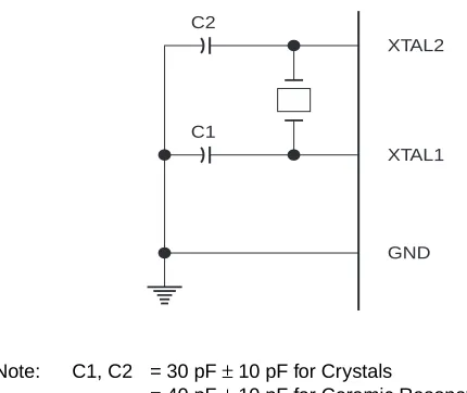
Oscillator Characteristics
XTAL1 and XTAL2 are the input and output, respectively, of an inverting amplifier which can be configured for use as an on-chip oscillator, as shown in Figure 1. Either a quartz crystal or ceramic resonator may be used. To drive the device from an external clock source, XTAL2 should be left unconnected while XTAL1 is driven as shown in Figure 2. There are no requirements on the duty cycle of the external clock signal, since the input to the internal clocking circuitry is through a divide-by-two flip-flop, but minimum and maxi-mum voltage high and low time specifications must be observed.
Idle Mode
In idle mode, the CPU puts itself to sleep while all the on-chip peripherals remain active. The mode is invoked by software. The content of the on-chip RAM and all the spe-cial functions registers remain unchanged during this mode. The idle mode can be terminated by any enabled interrupt or by a hardware reset.
[image:57.612.318.533.213.394.2]It should be noted that when idle is terminated by a hard ware reset, the device normally resumes program execu-tion, from where it left off, up to two machine cycles before the internal reset algorithm takes control. On-chip hardware inhibits access to internal RAM in this event, but access to the port pins is not inhibited. To eliminate the possibility of an unexpected write to a port pin when Idle is terminated by reset, the instruction following the one that invokes Idle should not be one that writes to a port pin or to external memory.
Figure 1. Oscillator Connections
Note: C1, C2 = 30 pF ± 10 pF for Crystals
= 40 pF ± 10 pF for Ceramic Resonators
Figure 2. External Clock Drive Configuration
C2
XTAL2
GND XTAL1 C1
Status of External Pins During Idle and Power Down Modes
Mode Program Memory ALE PSEN PORT0 PORT1 PORT2 PORT3
Idle Internal 1 1 Data Data Data Data
Idle External 1 1 Float Data Address Data
Power Down Internal 0 0 Data Data Data Data
[image:57.612.33.583.612.707.2]AT89C51
Power Down Mode
In the power down mode the oscillator is stopped, and the instruction that invokes power down is the last instruction executed. The on-chip RAM and Special Function Regis-ters retain their values until the power down mode is termi-nated. The only exit from power down is a hardware reset. Reset redefines the SFRs but does not change the on-chip RAM. The reset should not be activated before VCC is restored to its normal operating level and must be held active long enough to allow the oscillator to restart and sta-bilize.
Program Memory Lock Bits
On the chip are three lock bits which can be left unpro-grammed (U) or can be prounpro-grammed (P) to obtain the addi-tional features listed in the table below:
When lock bit 1 is programmed, the logic level at the EA pin is sampled and latched during reset. If the device is pow-ered up without a reset, the latch initializes to a random value, and holds that value until reset is activated. It is nec-essary that the latched value of EA be in agreement with the current logic level at that pin in order for the device to function properly.
Lock Bit Protection Modes
Program Lock Bits Protection Type
LB1 LB2 LB3
1 U U U No program lock features.
2 P U U MOVC instructions executed from external program memory are disabled from fetching code bytes from internal memory, EA is sampled and latched on reset, and further programming of the Flash is disabled.
3 P P U Same as mode 2, also verify is disabled.
4 P P P Same as mode 3, also external execution is disabled.
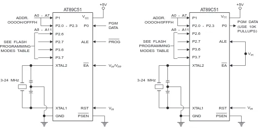
Programming the Flash
The AT89C51 is normally shipped with the on-chip Flash memory array in the erased state (that is, contents = FFH) and ready to be programmed. The programming interface accepts either a high-voltage (12-volt) or a low-voltage (VCC) program enable signal. The low voltage program-ming mode provides a convenient way to program the AT89C51 inside the userâs system, while the high-voltage programming mode is compatible with conventional third party Flash or EPROM programmers.
The AT89C51 is shipped with either the high-voltage or low-voltage programming mode enabled. The respective top-side marking and device signature codes are listed in the following table.
The AT89C51 code memory array is programmed byte-by-byte in either programming mode. To program any non-blank byte in the on-chip Flash Memory, the entire memory must be erased using the Chip Erase Mode.
Programming Algorithm: Before programming the
AT89C51, the address, data and control signals should be set up according to the Flash programming mode table and Figures 3 and 4. To program the AT89C51, take the follow-ing steps.
1. Input the desired memory location on the address lines.
2. Input the appropriate data byte on the data lines. 3. Activate the correct combination of control signals. 4. Raise EA/VPP to 12V for the high-voltage programming
mode.
5. Pulse ALE/PROG once to program a byte in the Flash array or the lock bits. The byte-write cycle is self-timed and typically takes no more than 1.5 ms. Repeat steps 1 through 5, changing the address and data for the entire array or until the end of the object file is reached.
Data Polling: The AT89C51 features Data Polling to
indi-cate the end of a write cycle. During a write cycle, an attempted read of the last byte written will result in the com-plement of the written datum on PO.7. Once the write cycle has been completed, true data are valid on all outputs, and the next cycle may begin. Data Polling may begin any time after a write cycle has been initiated.
Ready/Busy: The progress of byte programming can also
be monitored by the RDY/BSY output signal. P3.4 is pulled low after ALE goes high during programming to indicate BUSY. P3.4 is pulled high again when programming is done to indicate READY.
VPP = 12V VPP = 5V
Program Verify: If lock bits LB1 and LB2 have not been
programmed, the programmed code data can be read back via the address and data lines for verification. The lock bits cannot be verified directly. Verification of the lock bits is achieved by observing that their features are enabled.
Chip Erase: The entire Flash array is erased electrically
by using the proper combination of control signals and by holding ALE/PROG low for 10 ms. The code array is written with all â1âs. The chip erase operation must be executed before the code memory can be re-programmed.
Reading the Signature Bytes: The signature bytes are
read by the same procedure as a normal verification of locations 030H,
031H, and 032H, except that P3.6 and P3.7 must be pulled to a logic low. The values returned are as follows.
(030H) = 1EH indicates manufactured by Atmel (031H) = 51H indicates 89C51
(032H) = FFH indicates 12V programming (032H) = 05H indicates 5V programming
Programming Interface
Every code byte in the Flash array can be written and the entire array can be erased by using the appropriate combi-nation of control signals. The write operation cycle is self-timed and once initiated, will automatically time itself to completion.
All major programming vendors offer worldwide support for the Atmel microcontroller series. Please contact your local programming vendor for the appropriate software revision.
Flash Programming Modes
Note: 1. Chip Erase requires a 10-ms PROG pulse.
Mode RST PSEN ALE/PROG EA/VPP P2.6 P2.7 P3.6 P3.7
Write Code Data H L H/12V L H H H
Read Code Data H L H H L L H H
Write Lock Bit - 1 H L H/12V H H H H
Bit - 2 H L H/12V H H L L
Bit - 3 H L H/12V H L H L
Chip Erase H L H/12V H L L L
Read Signature Byte H L H H L L L L
AT89C51
Figure 3. Programming the Flash Figure 4. Verifying the Flash
P1
P2.6
P3.6 P2.0 - P2.3 A0 - A7
ADDR. OOOOH/OFFFH T SEE FLASH PROGRAMMING MODES ABLE 3-24 MHz
A8 - A11 P0
+5V
P2.7
PGM DATA PROG
V /VIH PP
VIH ALE P3.7 XTAL2 EA RST PSEN XTAL1 GND VCC AT89C51 P1 P2.6 P3.6 P2.0 - P2.3 A0 - A7
ADDR. OOOOH/0FFFH
3-24 MHz
A8 - A11
P0 +5V P2.7 PGM DATA (USE 10K PULLUPS) VIH VIH ALE P3.7 XTAL2 EA RST PSEN XTAL1 GND VCC AT89C51 T SEE FLASH PROGRAMMING MODES ABLE
Flash Programming and Verification Characteristics
TA = 0°C to 70°C, VCC = 5.0 ± 10%
Symbol Parameter Min Max Units
VPP(1) Programming Enable Voltage 11.5 12.5 V
IPP(1) Programming Enable Current 1.0 mA
1/tCLCL Oscillator Frequency 3 24 MHz
tAVGL Address Setup to PROG Low 48tCLCL
tGHAX Address Hold After PROG 48tCLCL
tDVGL Data Setup to PROG Low 48tCLCL
tGHDX Data Hold After PROG 48tCLCL
tEHSH P2.7 (ENABLE) High to VPP 48tCLCL
tSHGL VPP Setup to PROG Low 10 µs
tGHSL(1) VPP Hold After PROG 10 µs
tGLGH PROG Width 1 110 µs
tAVQV Address to Data Valid 48tCLCL
tELQV ENABLE Low to Data Valid 48tCLCL
tEHQZ Data Float After ENABLE 0 48tCLCL
tGHBL PROG High to BUSY Low 1.0 µs
[image:60.612.39.581.409.712.2]Flash Programming and Verification Waveforms - High Voltage Mode (V
PP= 12V)
tGLGH tGHSL
tAVGL tSHGL tDVGL tGHAX tAVQV tGHDX tEHSH tELQV tWC BUSY READY tGHBL tEHQZ P1.0 - P1.7
P2.0 - P2.3
ALE/PROG PORT 0 LOGIC 1 LOGIC 0 EA/VPP VPP P2.7 (ENABLE) P3.4 (RDY/BSY) PROGRAMMING ADDRESS VERIFICATION ADDRESS
DATA IN DATA OUT
Flash Programming and Verification Waveforms - Low Voltage Mode (V
PP= 5V)
tGLGH tAVGL tSHGL tDVGL tGHAX tAVQV tGHDX tEHSH tELQV tWC BUSY READY tGHBL tEHQZ P1.0 - P1.7
P2.0 - P2.3
ALE/PROG PORT 0 LOGIC 1 LOGIC 0 EA/VPP P2.7 (ENABLE) P3.4 (RDY/BSY) PROGRAMMING ADDRESS VERIFICATION ADDRESS
AT89C51
Absolute Maximum Ratings*
DC Characteristics
TA = -40°C to 85°C, VCC = 5.0V ± 20% (unless otherwise noted)
Notes: 1. Under steady state (non-transient) conditions, IOL must be externally limited as follows: Maximum IOL per port pin: 10 mA
Maximum IOL per 8-bit port: Port 0: 26 mA Ports 1, 2, 3: 15 mA Maximum total IOL for all output pins: 71 mA
If IOL exceeds the test condition, VOL may exceed the related specification. Pins are not guaranteed to sink current greater than the listed test conditions.
2. Minimum VCC for Power Down is 2V.
Operating Temperature ... -55°C to +125°C *NOTICE: Stresses beyond those listed under âAbsolute Maximum Ratingsâ may cause permanent dam-age to the device. This is a stress rating only and functional operation of the device at these or any other conditions beyond those indicated in the operational sections of this specification is not implied. Exposure to absolute maximum rating conditions for extended periods may affect device reliability.
Storage Temperature ... -65°C to +150°C
Voltage on Any Pin
with Respect to Ground ...-1.0V to +7.0V
Maximum Operating Voltage... 6.6V
DC Output Current... 15.0 mA
Symbol Parameter Condition Min Max Units
VIL Input Low Voltage (Except EA) -0.5 0.2 VCC - 0.1 V
VIL1 Input Low Voltage (EA) -0.5 0.2 VCC - 0.3 V
VIH Input High Voltage (Except XTAL1, RST) 0.2 VCC + 0.9 VCC + 0.5 V
VIH1 Input High Voltage (XTAL1, RST) 0.7 VCC VCC + 0.5 V
VOL Output Low Voltage(1) (Ports 1,2,3) IOL = 1.6 mA 0.45 V
VOL1 Output Low Voltage(1)
(Port 0, ALE, PSEN)
IOL = 3.2 mA 0.45 V
VOH Output High Voltage
(Ports 1,2,3, ALE, PSEN)
IOH = -60 µA, VCC = 5V ± 10% 2.4 V
IOH = -25 µA 0.75 VCC V
IOH = -10 µA 0.9 VCC V
VOH1 Output High Voltage
(Port 0 in External Bus Mode)
IOH = -800 µA, VCC = 5V ± 10% 2.4 V
IOH = -300 µA 0.75 VCC V
IOH = -80 µA 0.9 VCC V
IIL Logical 0 Input Current (Ports 1,2,3) VIN = 0.45V -50 µA
ITL Logical 1 to 0 Transition Current
(Ports 1,2,3)
VIN = 2V, VCC = 5V ± 10% -650 µA
ILI Input Leakage Current (Port 0, EA) 0.45 < VIN < VCC ±10 µA
RRST Reset Pulldown Resistor 50 300 Kâ¦
CIO Pin Capacitance Test Freq. = 1 MHz, TA = 25°C 10 pF
ICC Power Supply Current Active Mode, 12 MHz 20 mA
Idle Mode, 12 MHz 5 mA
Power Down Mode(2) VCC = 6V 100 µA
AC Characteristics
(Under Operating Conditions; Load Capacitance for Port 0, ALE/PROG, and PSEN = 100 pF; Load Capacitance for all other outputs = 80 pF)
External Program and Data Memory Characteristics
Symbol Parameter 12 MHz Oscillator 16 to 24 MHz Oscillator Units
Min Max Min Max
1/tCLCL Oscillator Frequency 0 24 MHz
tLHLL ALE Pulse Width 127 2tCLCL-40 ns
tAVLL Address Valid to ALE Low 43 tCLCL-13 ns
tLLAX Address Hold After ALE Low 48 tCLCL-20 ns
tLLIV ALE Low to Valid Instruction In 233 4tCLCL-65 ns
tLLPL ALE Low to PSEN Low 43 tCLCL-13 ns
tPLPH PSEN Pulse Width 205 3tCLCL-20 ns
tPLIV PSEN Low to Valid Instruction In 145 3tCLCL-45 ns
tPXIX Input Instruction Hold After PSEN 0 0 ns
tPXIZ Input Instruction Float After PSEN 59 tCLCL-10 ns
tPXAV PSEN to Address Valid 75 tCLCL-8 ns
tAVIV Address to Valid Instruction In 312 5tCLCL-55 ns
tPLAZ PSEN Low to Address Float 10 10 ns
tRLRH RD Pulse Width 400 6tCLCL-100 ns
tWLWH WR Pulse Width 400 6tCLCL-100 ns
tRLDV RD Low to Valid Data In 252 5tCLCL-90 ns
tRHDX Data Hold After RD 0 0 ns
tRHDZ Data Float After RD 97 2tCLCL-28 ns
tLLDV ALE Low to Valid Data In 517 8tCLCL-150 ns
tAVDV Address to Valid Data In 585 9tCLCL-165 ns
tLLWL ALE Low to RD or WR Low 200 300 3tCLCL-50 3tCLCL+50 ns
tAVWL Address to RD or WR Low 203 4tCLCL-75 ns
tQVWX Data Valid to WR Transition 23 tCLCL-20 ns
tQVWH Data Valid to WR High 433 7tCLCL-120 ns
tWHQX Data Hold After WR 33 tCLCL-20 ns
tRLAZ RD Low to Address Float 0 0 ns
AT89C51
External Program Memory Read Cycle
External Data Memory Read Cycle
t<