ABSTRACT
Technological moderenization of telecommunications have experienced of
growth swiftly, specially handphone. One of facility of handphone is SMS ( Short
Messege Services).
Water heater tank system with SMS which realized in Final Project meant
to arrangement of water heater tank system can be conducted from long distance.
Water heater system is designed with microcontroller MCS51 as processor of
temperature data input from SMS becoming set point for the water heater of tank
with temperature sensor LM 35 as feedback.
ABSTRAK
Moderenisasi teknologi telekomunikasi telah mengalami perkembangan
dengan cepat, khususnya
handphone
. Salah satu fasilitas dari
handphone
adalah
SMS (
Short Messege Services
).
Sistem pemanasan tangki air melalui SMS yang direalisasikan dalam
Tugas Akhir ini dimaksudkan agar pengaturan sistem pemanasan tangki air dapat
dilakukan dari jarak jauh. Sistem Pemanasan dirancang mengunakan
mikrokontroler MCS51 sebagai pemroses input data suhu dari SMS yang
menjadi set point untuk pemanasan tangki air dengan sensor suhu LM 35 sebagai
feedback.
DAFTAR ISI
LEMBAR PENGESAHAN
SURAT PERNYATAAN
ABSTRAK
i
ABSTRACT
ii
KATA PENGANTAR
iii
DAFTAR ISI
v
DAFTAR TABEL
viii
DAFTAR GAMBAR
ix
DAFTAR RUMUS
x
BAB I PENDAHULUAN
1
I.1. Latar Belakang
1
I.2. Identifikasi Masalah
1
I.3. Tujuan
1
I.4. Pembatasan Masalah
1
I.5. Spesifikasi Alat
2
I.6. Sistematika Penulisan
2
BAB II LANDASAN TEORI
3
II.1. Global System for Mobile communication (GSM)
3
II.1.1.
Short Message Services
(SMS)
3
II.1.1.1. AT
Command
3
II.1.1.1.1.
HyperTerminal
4
II.1.1.2. Mengubah 7bit Septet menjadi 8bit Oktet
4
II.1.1.3.
Protocol Description Unit (PDU)
5
II.1.1.3.1. PDU untuk Kirim SMS
5
II.1.1.3.2. PDU untuk Terima SMS
7
II.2. Mikrokontroler
9
II.2.1. Definisi Mikrokontroler
9
II.2.2. Arsitektur Atmel AT89S52
10
II.2.3.1. RAM Internal
16
II.2.3.2. Register Fungsi Khusus
17
II.2.3.2.1. Akumulator
18
II.2.3.2.2. Port
18
II.2.3.2.3. Register B
18
II.2.3.2.4. Stack Pointer
18
II.2.3.2.5.
Serial Data Buffer
(SBUF)
19
II.2.3.2.6.
Control Power
19
II.2.3.3.
Flash PEROM
19
II.2.3.4. Eksternal Memori
20
II.2.4. Antarmuka Serial
21
II.2.4.1.
Universal Asynchronous Transmitter/ Receiver
(UART)
21
II.2.4.2. Register Kontrol Port Serial
22
II.2.4.3.
Baudrate
23
II.2.5. Reset
26
II.2.6. Software
27
II.2.6.1. Program sumber
assembly
27
II.2.6.2. Program Objek
29
II.2.6.3.
Assembly listing
29
II.2.6.4. Program
Assembler
29
II.2.6.5. Program
Downloader
29
II.2.6.6. Petunjuk penggunaan ASM51.EXE
30
II.3.
Analog to Digital Converter
(ADC)
30
II.4. Sensor Suhu
30
II.4.1. Teknik Pensensoran Temperatur
30
II.4.1.1.
Resistance Temperatur Detektor
(RTD)
31
II.4.1.2.
Thermistor
31
II.4.1.3.
Thermocouple
31
II.4.1.4. Sensor Temperatur Silikon (ICs)
31
BAB III PERANCANGAN DAN REALISASI
33
III.1. Cara Kerja Alat
33
III.2.1. Mikrokontroler AT 89S52
34
III.2.2.
Analog to Digital Converter
(ADC)
35
III.2.3. Relai
37
III.3. Perancangan Software
38
BAB IV TABEL DAN DATA PENGAMATAN
43
IV.1. Hasil Pengujian Sensor Suhu LM 35
43
IV.1.1. Data Pemanasan
43
IV.1.2. Data Pendinginan
44
IV.2. Realisasi Tampilan Input Suhu
45
IV.3 Hasil Pengujian SMS
46
BAB V KESIMPULAN DAN SARAN
48
V.1. Kesimpulan
48
V.2. Saran
48
DAFTAR PUSTAKA
49
LAMPIRAN A
FOTO ALAT
A1
LAMPIRAN B
BAHASA ASSEMBLY (MCS51) DAN
B1
BAHASA PASCAL (BORLAND DELPHI 7)
B12
DAFTAR TABEL
Tabel II.1. Konversi karakter ke septet
4
Tabel II.2. Keterangan String yang Dikirim
6
Tabel II.3. Keterangan String yang Diterima
7
Tabel II.4. Deskripsi Pin AT89S52
13
Tabel II.5. Penentu Mode kerja Port Serial
22
Tabel II.6. Baudrate yang sering dipakai (1)
25
Tabel II.7. Baudrate yang sering dipakai (2)
25
Tabel II.8. Isi Register Setelah Reset
26
Tabel IV.1. Lamanya Pemanasan
43
DAFTAR GAMBAR
Gambar II.1. Pin AT 89S52
11
Gambar II.2. Rangkaian Oscillator
12
Gambar II.3. Peta Memori RAM
17
Gambar II.4. Peta Memori
Special Function Register
17
Gambar II.5. Program dan Struktur Data AT89S52
20
Gambar II.6. Susunan Bit dalam register SCON
22
Gambar II.7. Dasar Sensor Temperatur LM 35
32
Gambar II.8. Jangkauan Temperatur LM 35
32
Gambar III.1. Diagram Blok Alat
33
Gambar III.2. Rangkaian Utama
35
Gambar III.3. ADC 0804 dalam keadaan freerunning
36
Gambar III.4. Transistor Penyangga dan Relai
37
Gambar III.5. Flowchart Utama
39
Gambar III.6. Flowchart Subrutine Serial
40
Gambar III.7. Flowchart Subrutine Terima Data
40
Gambar III.8. Flowchart Subrutine Kirim Data
41
Gambar III.9. Flowchart Subrutine Sistem Pemanas
41
Gambar III.10. Flowchart Borland Delphi
42
Gambar IV.1. Grafik data Pemanasan
43
Gambar IV.2. Grafik data Pendinginan
44
Gambar IV.3. Form Input Suhu
45
Gambar IV.4. Respon Pesan Terkirim
45
Gambar IV.5. Respon suhu sudah tercapai
46
DAFTAR RUMUS
Rumus (II.1)
23
Rumus (II.2)
23
Rumus (II.3)
24
Rumus (II.4)
24
LM35
Precision Centigrade Temperature Sensors
General Description
The LM35 series are precision integrated-circuit temperature sensors, whose output voltage is linearly proportional to the Celsius (Centigrade) temperature. The LM35 thus has an advantage over linear temperature sensors calibrated in ˚ Kelvin, as the user is not required to subtract a large constant voltage from its output to obtain convenient Centi-grade scaling. The LM35 does not require any external calibration or trimming to provide typical accuracies of±1⁄4˚C
at room temperature and ±3⁄4˚C over a full −55 to +150˚C
temperature range. Low cost is assured by trimming and calibration at the wafer level. The LM35’s low output imped-ance, linear output, and precise inherent calibration make interfacing to readout or control circuitry especially easy. It can be used with single power supplies, or with plus and minus supplies. As it draws only 60 µA from its supply, it has very low self-heating, less than 0.1˚C in still air. The LM35 is rated to operate over a −55˚ to +150˚C temperature range, while the LM35C is rated for a −40˚ to +110˚C range (−10˚ with improved accuracy). The LM35 series is available
pack-aged in hermetic TO-46 transistor packages, while the LM35C, LM35CA, and LM35D are also available in the plastic TO-92 transistor package. The LM35D is also avail-able in an 8-lead surface mount small outline package and a plastic TO-220 package.
Features
n Calibrated directly in ˚ Celsius (Centigrade)
n Linear + 10.0 mV/˚C scale factor
n 0.5˚C accuracy guaranteeable (at +25˚C)
n Rated for full −55˚ to +150˚C range
n Suitable for remote applications
n Low cost due to wafer-level trimming
n Operates from 4 to 30 volts
n Less than 60 µA current drain
n Low self-heating, 0.08˚C in still air
n Nonlinearity only±1⁄4˚C typical
n Low impedance output, 0.1Ωfor 1 mA load
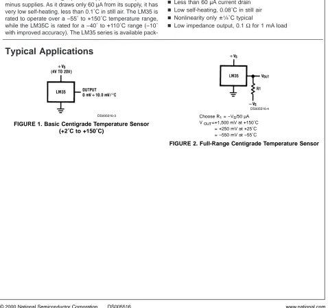
Typical Applications
DS005516-3
FIGURE 1. Basic Centigrade Temperature Sensor (+2˚C to +150˚C)
DS005516-4
Choose R1= −VS/50 µA
VOUT=+1,500 mV at +150˚C
= +250 mV at +25˚C = −550 mV at −55˚C
FIGURE 2. Full-Range Centigrade Temperature Sensor November 2000
LM35
Precision
Centigrade
T
emperature
Connection Diagrams
TO-46 Metal Can Package*
DS005516-1
*Case is connected to negative pin (GND)
Order Number LM35H, LM35AH, LM35CH, LM35CAH or LM35DH
See NS Package Number H03H
TO-92 Plastic Package
DS005516-2
Order Number LM35CZ, LM35CAZ or LM35DZ See NS Package Number Z03A
SO-8
Small Outline Molded Package
DS005516-21
N.C. = No Connection
Top View Order Number LM35DM See NS Package Number M08A
TO-220 Plastic Package*
DS005516-24
*Tab is connected to the negative pin (GND).
Note: The LM35DT pinout is different than the discontinued LM35DP. Order Number LM35DT
See NS Package Number TA03F
Absolute Maximum Ratings
(Note 10)If Military/Aerospace specified devices are required, please contact the National Semiconductor Sales Office/ Distributors for availability and specifications.
Supply Voltage +35V to −0.2V
Output Voltage +6V to −1.0V
Output Current 10 mA
Storage Temp.;
TO-46 Package, −60˚C to +180˚C
TO-92 Package, −60˚C to +150˚C
SO-8 Package, −65˚C to +150˚C
TO-220 Package, −65˚C to +150˚C
Lead Temp.: TO-46 Package,
(Soldering, 10 seconds) 300˚C
TO-92 and TO-220 Package,
(Soldering, 10 seconds) 260˚C
SO Package (Note 12)
Vapor Phase (60 seconds) 215˚C
Infrared (15 seconds) 220˚C
ESD Susceptibility (Note 11) 2500V
Specified Operating Temperature Range: TMINto TMAX
(Note 2)
LM35, LM35A −55˚C to +150˚C
LM35C, LM35CA −40˚C to +110˚C
LM35D 0˚C to +100˚C
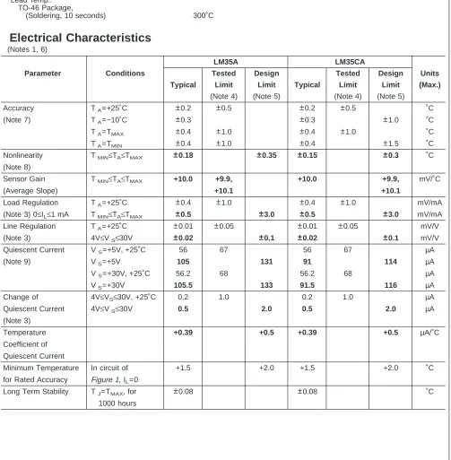
Electrical Characteristics
(Notes 1, 6)LM35A LM35CA
Parameter Conditions Tested Design Tested Design Units Typical Limit Limit Typical Limit Limit (Max.)
(Note 4) (Note 5) (Note 4) (Note 5)
Accuracy TA=+25˚C ±0.2 ±0.5 ±0.2 ±0.5 ˚C
(Note 7) TA=−10˚C ±0.3 ±0.3 ±1.0 ˚C
TA=TMAX ±0.4 ±1.0 ±0.4 ±1.0 ˚C
TA=TMIN ±0.4 ±1.0 ±0.4 ±1.5 ˚C
Nonlinearity TMIN≤TA≤TMAX ±0.18 ±0.35 ±0.15 ±0.3 ˚C
(Note 8)
Sensor Gain TMIN≤TA≤TMAX +10.0 +9.9, +10.0 +9.9, mV/˚C
(Average Slope) +10.1 +10.1
Load Regulation TA=+25˚C ±0.4 ±1.0 ±0.4 ±1.0 mV/mA
(Note 3) 0≤IL≤1 mA TMIN≤TA≤TMAX ±0.5 ±3.0 ±0.5 ±3.0 mV/mA
Line Regulation TA=+25˚C ±0.01 ±0.05 ±0.01 ±0.05 mV/V
(Note 3) 4V≤VS≤30V ±0.02 ±0.1 ±0.02 ±0.1 mV/V
Quiescent Current VS=+5V, +25˚C 56 67 56 67 µA
(Note 9) VS=+5V 105 131 91 114 µA
VS=+30V, +25˚C 56.2 68 56.2 68 µA
VS=+30V 105.5 133 91.5 116 µA
Change of 4V≤VS≤30V, +25˚C 0.2 1.0 0.2 1.0 µA
Quiescent Current 4V≤VS≤30V 0.5 2.0 0.5 2.0 µA
(Note 3)
Temperature +0.39 +0.5 +0.39 +0.5 µA/˚C
Coefficient of Quiescent Current
Minimum Temperature In circuit of +1.5 +2.0 +1.5 +2.0 ˚C
for Rated Accuracy Figure 1, IL=0
Long Term Stability TJ=TMAX, for ±0.08 ±0.08 ˚C
1000 hours
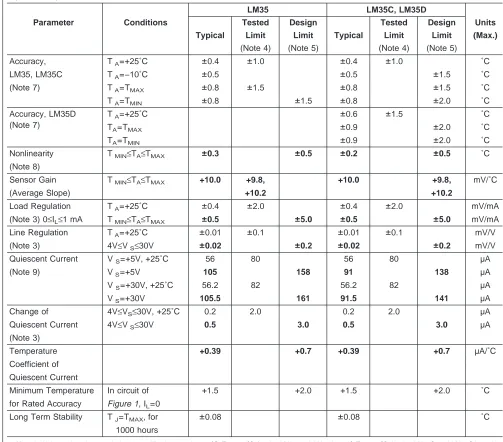
Electrical Characteristics
(Notes 1, 6)LM35 LM35C, LM35D
Parameter Conditions Tested Design Tested Design Units Typical Limit Limit Typical Limit Limit (Max.)
(Note 4) (Note 5) (Note 4) (Note 5)
Accuracy, TA=+25˚C ±0.4 ±1.0 ±0.4 ±1.0 ˚C
LM35, LM35C TA=−10˚C ±0.5 ±0.5 ±1.5 ˚C
(Note 7) TA=TMAX ±0.8 ±1.5 ±0.8 ±1.5 ˚C
TA=TMIN ±0.8 ±1.5 ±0.8 ±2.0 ˚C
Accuracy, LM35D (Note 7)
TA=+25˚C ±0.6 ±1.5 ˚C
TA=TMAX ±0.9 ±2.0 ˚C
TA=TMIN ±0.9 ±2.0 ˚C
Nonlinearity TMIN≤TA≤TMAX ±0.3 ±0.5 ±0.2 ±0.5 ˚C
(Note 8)
Sensor Gain TMIN≤TA≤TMAX +10.0 +9.8, +10.0 +9.8, mV/˚C
(Average Slope) +10.2 +10.2
Load Regulation TA=+25˚C ±0.4 ±2.0 ±0.4 ±2.0 mV/mA
(Note 3) 0≤IL≤1 mA TMIN≤TA≤TMAX ±0.5 ±5.0 ±0.5 ±5.0 mV/mA
Line Regulation TA=+25˚C ±0.01 ±0.1 ±0.01 ±0.1 mV/V
(Note 3) 4V≤VS≤30V ±0.02 ±0.2 ±0.02 ±0.2 mV/V
Quiescent Current VS=+5V, +25˚C 56 80 56 80 µA
(Note 9) VS=+5V 105 158 91 138 µA
VS=+30V, +25˚C 56.2 82 56.2 82 µA
VS=+30V 105.5 161 91.5 141 µA
Change of 4V≤VS≤30V, +25˚C 0.2 2.0 0.2 2.0 µA
Quiescent Current 4V≤VS≤30V 0.5 3.0 0.5 3.0 µA
(Note 3)
Temperature +0.39 +0.7 +0.39 +0.7 µA/˚C
Coefficient of Quiescent Current
Minimum Temperature In circuit of +1.5 +2.0 +1.5 +2.0 ˚C
for Rated Accuracy Figure 1, IL=0
Long Term Stability TJ=TMAX, for ±0.08 ±0.08 ˚C
1000 hours
Note 1: Unless otherwise noted, these specifications apply: −55˚C≤TJ≤+150˚C for the LM35 and LM35A; −40˚≤TJ≤+110˚C for the LM35C and LM35CA; and 0˚≤TJ≤+100˚C for the LM35D. VS=+5Vdc and ILOAD=50 µA, in the circuit ofFigure 2. These specifications also apply from +2˚C to TMAXin the circuit ofFigure 1. Specifications in boldface apply over the full rated temperature range.
Note 2: Thermal resistance of the TO-46 package is 400˚C/W, junction to ambient, and 24˚C/W junction to case. Thermal resistance of the TO-92 package is
180˚C/W junction to ambient. Thermal resistance of the small outline molded package is 220˚C/W junction to ambient. Thermal resistance of the TO-220 package is 90˚C/W junction to ambient. For additional thermal resistance information see table in the Applications section.
Note 3: Regulation is measured at constant junction temperature, using pulse testing with a low duty cycle. Changes in output due to heating effects can be
computed by multiplying the internal dissipation by the thermal resistance.
Note 4: Tested Limits are guaranteed and 100% tested in production.
Note 5: Design Limits are guaranteed (but not 100% production tested) over the indicated temperature and supply voltage ranges. These limits are not used to
calculate outgoing quality levels.
Note 6: Specifications in boldface apply over the full rated temperature range.
Note 7: Accuracy is defined as the error between the output voltage and 10mv/˚C times the device’s case temperature, at specified conditions of voltage, current,
and temperature (expressed in ˚C).
Note 8: Nonlinearity is defined as the deviation of the output-voltage-versus-temperature curve from the best-fit straight line, over the device’s rated temperature
range.
Note 9: Quiescent current is defined in the circuit ofFigure 1.
Note 10: Absolute Maximum Ratings indicate limits beyond which damage to the device may occur. DC and AC electrical specifications do not apply when operating
the device beyond its rated operating conditions. See Note 1.
Note 11: Human body model, 100 pF discharged through a 1.5 kΩresistor.
Typical Performance Characteristics
Thermal Resistance Junction to Air
DS005516-25
Thermal Time Constant
DS005516-26
Thermal Response in Still Air
DS005516-27
Thermal Response in Stirred Oil Bath
DS005516-28
Minimum Supply Voltage vs. Temperature
DS005516-29
Quiescent Current vs. Temperature (In Circuit ofFigure 1.)
DS005516-30
Quiescent Current vs. Temperature (In Circuit ofFigure 2.)
DS005516-31
Accuracy vs. Temperature (Guaranteed)
DS005516-32
Accuracy vs. Temperature (Guaranteed)
DS005516-33
Typical Performance Characteristics
(Continued)Applications
The LM35 can be applied easily in the same way as other integrated-circuit temperature sensors. It can be glued or cemented to a surface and its temperature will be within about 0.01˚C of the surface temperature.
This presumes that the ambient air temperature is almost the same as the surface temperature; if the air temperature were much higher or lower than the surface temperature, the actual temperature of the LM35 die would be at an interme-diate temperature between the surface temperature and the air temperature. This is expecially true for the TO-92 plastic package, where the copper leads are the principal thermal path to carry heat into the device, so its temperature might be closer to the air temperature than to the surface tempera-ture.
To minimize this problem, be sure that the wiring to the LM35, as it leaves the device, is held at the same tempera-ture as the surface of interest. The easiest way to do this is to cover up these wires with a bead of epoxy which will insure that the leads and wires are all at the same tempera-ture as the surface, and that the LM35 die’s temperatempera-ture will not be affected by the air temperature.
The TO-46 metal package can also be soldered to a metal surface or pipe without damage. Of course, in that case the V− terminal of the circuit will be grounded to that metal. Alternatively, the LM35 can be mounted inside a sealed-end metal tube, and can then be dipped into a bath or screwed into a threaded hole in a tank. As with any IC, the LM35 and accompanying wiring and circuits must be kept insulated and dry, to avoid leakage and corrosion. This is especially true if the circuit may operate at cold temperatures where conden-sation can occur. Printed-circuit coatings and varnishes such as Humiseal and epoxy paints or dips are often used to insure that moisture cannot corrode the LM35 or its connec-tions.
These devices are sometimes soldered to a small
light-weight heat fin, to decrease the thermal time constant and speed up the response in slowly-moving air. On the other hand, a small thermal mass may be added to the sensor, to give the steadiest reading despite small deviations in the air temperature.
Temperature Rise of LM35 Due To Self-heating (Thermal Resistance,
θ
JA)
TO-46, TO-46*, TO-92, TO-92**, SO-8 SO-8** TO-220 no heat
sink
small heat fin no heat sink
small heat fin no heat sink
small heat fin no heat sink
Still air 400˚C/W 100˚C/W 180˚C/W 140˚C/W 220˚C/W 110˚C/W 90˚C/W
Moving air 100˚C/W 40˚C/W 90˚C/W 70˚C/W 105˚C/W 90˚C/W 26˚C/W
Still oil 100˚C/W 40˚C/W 90˚C/W 70˚C/W
Stirred oil 50˚C/W 30˚C/W 45˚C/W 40˚C/W
(Clamped to metal,
Infinite heat sink) (24˚C/W) (55˚C/W)
*Wakefield type 201, or 1" disc of 0.020" sheet brass, soldered to case, or similar.
**TO-92 and SO-8 packages glued and leads soldered to 1" square of 1/16" printed circuit board with 2 oz. foil or similar.
Noise Voltage
DS005516-34
Start-Up Response
DS005516-35
Typical Applications
CAPACITIVE LOADS
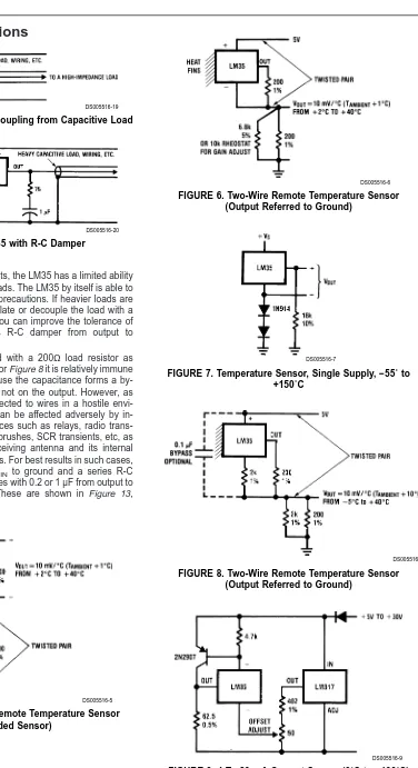
Like most micropower circuits, the LM35 has a limited ability to drive heavy capacitive loads. The LM35 by itself is able to drive 50 pf without special precautions. If heavier loads are anticipated, it is easy to isolate or decouple the load with a resistor; seeFigure 3. Or you can improve the tolerance of capacitance with a series R-C damper from output to ground; seeFigure 4.
When the LM35 is applied with a 200Ω load resistor as shown inFigure 5, Figure 6 or Figure 8 it is relatively immune to wiring capacitance because the capacitance forms a by-pass from ground to input, not on the output. However, as with any linear circuit connected to wires in a hostile envi-ronment, its performance can be affected adversely by in-tense electromagnetic sources such as relays, radio trans-mitters, motors with arcing brushes, SCR transients, etc, as its wiring can act as a receiving antenna and its internal junctions can act as rectifiers. For best results in such cases, a bypass capacitor from VIN to ground and a series R-C
damper such as 75Ωin series with 0.2 or 1 µF from output to ground are often useful. These are shown in Figure 13, Figure 14, and Figure 16.
DS005516-19
FIGURE 3. LM35 with Decoupling from Capacitive Load
DS005516-20
FIGURE 4. LM35 with R-C Damper
DS005516-5
FIGURE 5. Two-Wire Remote Temperature Sensor (Grounded Sensor)
DS005516-6
FIGURE 6. Two-Wire Remote Temperature Sensor (Output Referred to Ground)
DS005516-7
FIGURE 7. Temperature Sensor, Single Supply, −55˚ to +150˚C
DS005516-8
FIGURE 8. Two-Wire Remote Temperature Sensor (Output Referred to Ground)
Typical Applications
(Continued)DS005516-10
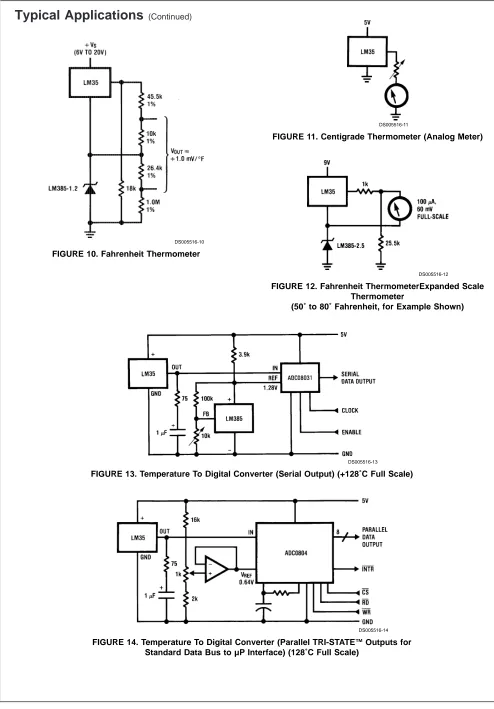
FIGURE 10. Fahrenheit Thermometer
DS005516-11
FIGURE 11. Centigrade Thermometer (Analog Meter)
DS005516-12
FIGURE 12. Fahrenheit ThermometerExpanded Scale Thermometer
(50˚ to 80˚ Fahrenheit, for Example Shown)
DS005516-13
FIGURE 13. Temperature To Digital Converter (Serial Output) (+128˚C Full Scale)
DS005516-14
FIGURE 14. Temperature To Digital Converter (Parallel TRI-STATE™Outputs for Standard Data Bus to µP Interface) (128˚C Full Scale)
Typical Applications
(Continued)DS005516-16
*=1% or 2% film resistor Trim RBfor VB=3.075V
Trim RCfor VC=1.955V
Trim RAfor VA=0.075V + 100mV/˚C x Tambient
Example, VA=2.275V at 22˚C
FIGURE 15. Bar-Graph Temperature Display (Dot Mode)
DS005516-15
FIGURE 16. LM35 With Voltage-To-Frequency Converter And Isolated Output (2˚C to +150˚C; 20 Hz to 1500 Hz)
Block Diagram
DS005516-23
Physical Dimensions
inches (millimeters) unless otherwise notedTO-46 Metal Can Package (H) Order Number LM35H, LM35AH, LM35CH,
LM35CAH, or LM35DH NS Package Number H03H
SO-8 Molded Small Outline Package (M) Order Number LM35DM NS Package Number M08A
Physical Dimensions
inches (millimeters) unless otherwise noted (Continued)Power Package TO-220 (T) Order Number LM35DT NS Package Number TA03F
Physical Dimensions
inches (millimeters) unless otherwise noted (Continued)LIFE SUPPORT POLICY
NATIONAL’S PRODUCTS ARE NOT AUTHORIZED FOR USE AS CRITICAL COMPONENTS IN LIFE SUPPORT DEVICES OR SYSTEMS WITHOUT THE EXPRESS WRITTEN APPROVAL OF THE PRESIDENT AND GENERAL COUNSEL OF NATIONAL SEMICONDUCTOR CORPORATION. As used herein:
1. Life support devices or systems are devices or systems which, (a) are intended for surgical implant into the body, or (b) support or sustain life, and whose failure to perform when properly used in accordance with instructions for use provided in the labeling, can be reasonably expected to result in a significant injury to the user.
2. A critical component is any component of a life support device or system whose failure to perform can be reasonably expected to cause the failure of the life support device or system, or to affect its safety or effectiveness.
National Semiconductor Corporation
Americas Tel: 1-800-272-9959
National Semiconductor Europe
Fax: +49 (0) 180-530 85 86 Email: [email protected]
National Semiconductor Asia Pacific Customer Response Group
Tel: 65-2544466
National Semiconductor Japan Ltd.
Tel: 81-3-5639-7560 Fax: 81-3-5639-7507
TO-92 Plastic Package (Z)
Order Number LM35CZ, LM35CAZ or LM35DZ NS Package Number Z03A
LM35
Precision
Centigrade
T
emperature
= assembler =
$mod51
org 00h
main: mov sbuf,#00h
lcall init
mov p2,#00h
init_hp:lcall ate_1
setb p2.0
lcall at_cnmi
setb p2.1
main1:
cek0: lcall inchar
cjne a,#'1',cek0
setb p2.2
clr p2.2
lcall at_cmgr
lcall delay500m
lcall at_cmgr
clr p2.1
cok: lcall inchar
cjne a,#'0',cok
mov r1,#20h
clr p2.0
lagi1: lcall inchar
mov @r1,a
inc r1
cjne a,#0dh,lagi1
yu: lcall inchar
setb p2.0
lcall at_cmgd
mov p2,#0ffh
ya: lcall inchar
cjne a,#'K',ya
mov p2,#00h
lcall delay100m
mov r1,#55h
mov a,@r1
mov p2,a
lcall delay500m
cjne a,#41h,bb
mov a,#0ah
ajmp dd
bb: cjne a,#42h,cc
mov a,#0bh
ajmp dd
cc: cjne a,#43h,dd
mov a,#0ch
dd: anl a,#0fh
mov p2,a
lcall delay500m
rl a
mov r0,#56h
mov a,@r0
mov p2,a
lcall delay500m
anl a,#0fh
mov p2,a
lcall delay500m
add a,b
mov p2,a
lcall delay500m
mov r1,#30h
mov @r1,a
anl a,#80h
cjne a,#80h,no_C
mov r1,#70h
mov a,@r1
mov p2,a
lcall delay500m
anl a,#0fh
mov p2,a
lcall delay500m
rl a
rl a
rl a
rl a
mov p2,a
lcall delay500m
mov b,a
mov r0,#58h
mov a,@r0
mov p2,a
lcall delay500m
cjne a,#41h,bb1
mov a,#0ah
ajmp dd1
bb1: cjne a,#42h,cc1
mov a,#0bh
ajmp dd1
cc1: cjne a,#43h,dd1
mov a,#0ch
dd1: anl a,#00fh
mov p2,a
lcall delay500m
add a,b
lcall delay500m
mov r1,#32h
mov @r1,a
rl a
mov p2,a
lcall delay500m
mov r1,#32h
mov @r1,a
mov r1,#70h
mov a,@r1
cjne a,#01h,no_C1
mov r1,#32h
mov a,@r1
add a,#01h
mov p2,a
lcall delay500m
mov r1,#31h
mov @r1,a
ajmp tampil
no_C1: mov r1,#32h
mov a,@r1
mov r1,#31h
mov @r1,a
rl a
mov b,a
lcall delay1s
mov r1,#31h
mov a,@r1
anl a,#0fh
add a,b
mov r0,#32h
mov @r0,a
lcall delay1s
; a set point
; b lm 35
lg: mov a,r5
mov b,p0
cjne a,b,satu
sjmp lg
satu: jc kecil
sjmp besar
besar: ajmp pemanas
kecil: ajmp valve
pemanas:
setb p2.7
cjne a,b,lg
sjmp sukses
valve:
setb p2.6
cjne a,b,valve
sjmp sukses
mov dptr,#jml_Ok
lcall outstr
mov a,#0dh
lcall outchr
setb p2.3
lcall siku
clr p2.3
mov dptr,#Ok
lcall outstr
lcall ctrl_Z
clr p2.2
ye: lcall inchar
cjne a,#'K',ye
lcall delay1s
ljmp main1
;======= kirim ate1 =======
ate_1: mov dptr,#ate1
lcall outstr
mov a,#0dh
lcall outchr
ret
;======= kirim at+cmps =======
at_cnmi:mov dptr,#cnmi
;======= kirim at+cmgr =======
at_cmgr:mov dptr,#cmgr
lcall outstr
mov a,#0dh
lcall outchr
ret
;======= kirim at+cmgd =======
at_cmgd:mov dptr,#cmgd
lcall outstr
mov a,#0dh
lcall outchr
ret
;====== kirim at+cmgs= ======
at_cmgs:mov dptr,#cmgs
lcall outstr
ret
;====== cek tanda > ======
siku:
cek3: lcall inchar
cjne a,#'>',cek3
ret
;======
kirim ctrl Z ======
ctrl_Z:
lcall outchr
ret
;======= Inisialisasi UC ========
init: mov tmod,#20h
mov pcon,#80h
mov TH1,#0fdh
setb TR1
mov scon,#52h
ret
outstr: clr a
movc a,@a+dptr
jz exit
lcall outchr
inc dptr
lcall delay50m
jmp outstr
exit: ret
inchar: clr a
jnb ri,inchar
clr ri
mov a,sbuf
ret
;=========DELAY_50mS=========
delay50m: mov r5,#50
d50m2: mov r6,#04h
d50m3: mov r7,#0ffh
djnz r7,$
djnz r6,d50m3
djnz r5,d50m2
ret
;=========DELAY_100mS=========
delay100m: mov r5,#100
d100m2: mov r6,#04h
d100m3: mov r7,#0ffh
djnz r7,$
djnz r6,d100m3
djnz r5,d100m2
ret
;=========DELAY_500mS=========
delay500m: lcall delay100m
lcall delay100m
lcall delay100m
lcall delay100m
lcall delay100m
ret
;==========DELAY_1S===========
delay1s: lcall delay500m
;=======Inisialisasi HP=======
ate1: db 'ate1',0
cnmi: db 'at+cnmi=1,1,0,1,1',0
cmgr: db 'at+cmgr=1',0
cmgd: db 'at+cmgd=1',0
cmgs: db 'at+cmgs=',0
;=========JUMLAH_PDU==========
jml_Ok: db '1','5',0
jml_Err: db '1','8',0
;=========PDU_LAPORAN=========
Ok: db '0691261801000011000A81808102196800000B02CF35',0
Err: db '0691261801000011000A81808102196800000B0545B9FC2D07',0
= Borland Delphi =
unit U_sms2;
interface
uses
Windows, Messages, SysUtils, Variants, Classes, Graphics, Controls, Forms,
Dialogs, StdCtrls, Mask, sCustomComboEdit, sCurrEdit, sButtonControl,
sCustomButton, ComCtrls, sPageControl, jpeg, ExtCtrls, AfPortControls,
AfDataDispatcher, AfComPort, sTooledit;
type
TForm1 = class(TForm)
Image1: TImage;
sBitBtn1: TsBitBtn;
sCalcEdit1: TsCalcEdit;
AfComPort1: TAfComPort;
AfDataDispatcher1: TAfDataDispatcher;
sDateEdit1: TsDateEdit;
AfPortRadioGroup1: TAfPortRadioGroup;
Timer1: TTimer;
Label1: TLabel;
sBitBtn2: TsBitBtn;
Memo1: TMemo;
GroupBox1: TGroupBox;
Edit1: TEdit;
Label2: TLabel;
Button1: TButton;
Label3: TLabel;
sBitBtn3: TsBitBtn;
Image2: TImage;
procedure sBitBtn1Click(Sender: TObject);
procedure Button1Click(Sender: TObject);
procedure Timer1Timer(Sender: TObject);
procedure AfDataDispatcher1DataReceived(Sender: TObject);
procedure sBitBtn2Click(Sender: TObject);
procedure sBitBtn3Click(Sender: TObject);
private
{ Private declarations }
public
{ Public declarations }
end;
Form1: TForm1;
implementation
{$R *.dfm}
var
suhu : string;
s1,s2,s3,s4,data : string ;
u : integer ;
procedure TForm1.sBitBtn1Click(Sender: TObject);
begin
u := 13 ;
s2 := '0691261801000011000B818021123098F90000A702'+suhu ;
s1 := 'at+cmgs=16' ;
form1.AfDataDispatcher1.WriteString(s1);
form1.AfDataDispatcher1.WriteData(u,1);
form1.Timer1.Enabled := true;
end;
procedure TForm1.Button1Click(Sender: TObject);
begin
suhu := edit1.text ;
end;
procedure TForm1.Timer1Timer(Sender: TObject);
begin
form1.AfDataDispatcher1.WriteString(s2);
u := 26 ;
form1.AfDataDispatcher1.WriteData(u,1);
form1.Timer1.Enabled := false;
form1.Label1.Caption := 'PESAN TERKIRIM' ;
end;
var
u1 : integer =0 ;
procedure TForm1.AfDataDispatcher1DataReceived(Sender: TObject);
var
sms : string;
sms1 : integer;
begin
inc(u1);
if ( (0 < u1) or (u1<= 2)) then
begin
memo1.Lines.Add(sms);
end;
if(u1>5) then
begin
s2 := 'at+cmgd=1';
form1.AfDataDispatcher1.WriteString(s2);
u := 13;
form1.AfDataDispatcher1.WriteData(u,1);
label1.Caption := 'Sukses' ;
end;
end;
procedure TForm1.sBitBtn2Click(Sender: TObject);
begin
s1 := 'at+cnmi=1,1,0,1,1';
u := 13 ;
form1.AfDataDispatcher1.WriteString(s1);
form1.AfDataDispatcher1.WriteData(u,1);
end;
procedure TForm1.sBitBtn3Click(Sender: TObject);
var
s6 : string;
x : integer;
begin
s6 := 'at+calm=1' ;
form1.AfDataDispatcher1.WriteString(s6);
x := 13 ;
form1.AfDataDispatcher1.WriteData(x,1);
end;
AT Command Set Reference Manual
Manual Reference
AT Command Set
(GSM 07.07, GSM 07.05,
Siemens specific commands)
for the SIEMENS Mobile Phones
AT Command Set Reference Manual
The command descriptions or example sequences in this document imply no liability or warranty in any way. The author therefore will take no responsibility and will accept no liability which results of using the content of this document in any way.
All rights reserved. No part of this work covered by the copyrights hereof may be reproduced or copied in any form or by any means (graphic, electronic, or mechanical, including photocopying, taping, or information storage and retrieval systems) without written permission of the publisher.
Revisions Overview
[image:37.596.80.534.201.249.2] [image:37.596.72.529.293.536.2]Date Version Name Description of revision 15-03-2000 1.0 Kel created
Table of Contents
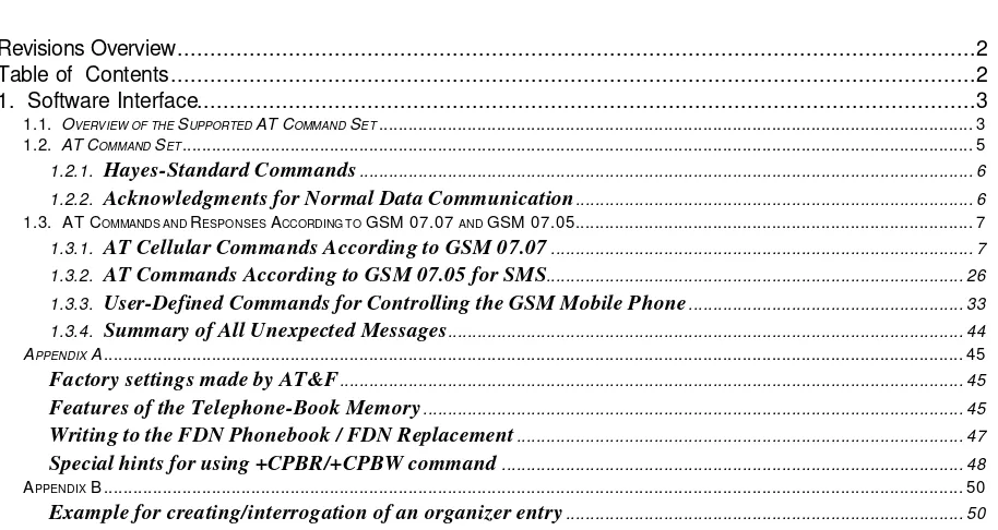
Revisions Overview...2 Table of Contents...2 1. Software Interface...3
1.1. OVERVIEW OF THE SUPPORTED AT COMMAND SET... 3 1.2. AT COMMAND SET... 5 1.2.1. Hayes-Standard Commands... 6 1.2.2. Acknowledgments for Normal Data Communication... 6 1.3. AT COMMANDS AND RESPONSES ACCORDING TO GSM 07.07 AND GSM 07.05... 7
1.3.1. AT Cellular Commands According to GSM 07.07... 7 1.3.2. AT Commands According to GSM 07.05 for SMS... 26 1.3.3. User-Defined Commands for Controlling the GSM Mobile Phone... 33 1.3.4. Summary of All Unexpected Messages... 44 APPENDIX A... 45
Factory settings made by AT&F... 45
Features of the Telephone-Book Memory... 45
Writing to the FDN Phonebook / FDN Replacement... 47
Special hints for using +CPBR/+CPBW command... 48 APPENDIX B ... 50
AT Command Set Reference Manual
1. Software Interface
1.1. Overview of the Supported AT Command Set
Page Commands 07.07
Function
7 AT+CGMI Issue manufacturer ID code
7 AT+CGMM Issue model ID code
7 AT+CGMR Output the GSM telephone version
8 AT+CGSN Output the serial number (IMEI)
8 AT+GSN Output the serial number (IMEI)
8 AT+CHUP Terminate call
8 AT+CEER Query the reason for disconnection of last call
9 AT+CREG Network registration
9 AT+COPS Commands concerning selection of network operator
10 AT+CLCK Switch locks on and off
10 AT+CPWD Change password to a lock
11 AT+CLIP Display telephone number of calling party
11 AT+CCFC Call forwarding
12 AT+CHLD Call hold and multiparty
12 AT+CPAS Query the telephone status
13 AT+CPIN Enter PIN and query lock
13 AT+CBC Battery charge
14 AT+CSQ Output signal quality
14 AT+CPBS Select a telephone book
15 Fehler! Kein gültiges Resultat für Tabelle.
Read a telephone-book entry
15 AT+CPBW Write a telephone-book entry
16 AT+CMEE Expanded error messages according to GSM 07.07
17 AT+VTS Send a DTMF tone
18 AT+VTD Set duration of a DTMF tone
18 AT+WS46 Select wireless network
18 AT+CSCS Select TE character set
19 AT+CAOC Advice of charge
19 AT+CSSN Supplementary service notifications
20 AT+CRSM Restricted SIM access
20 AT+CIMI Output of IMSI
21 AT+CACM Accumulated call meter
21 AT+CAMM Accumulated call meter maximum
22 AT+CLCC List Current Calls
23 AT+CCLK Clock
23 AT+COPN Read operator names
23 AT+CPUC Price per unit and currency table
24 AT+CALM Alert sound mode
24 AT+CRSL Ringer sound level
24 AT+CLVL Loudspeaker volume level
24 AT+CMUT Mute control
AT Command Set Reference Manual
Page Commands 07.05
Function
26 AT+CSMS Selection of message service
27 AT+CPMS Selection of SMS memory
27 AT+CMGF SMS format
28 AT+CSCA Address of the SMS service center
28 AT+CNMI Display new incoming SMS
29 AT+CNMA Acknowledgment of a short message directly output
30 AT+CMGL List SMS
31 AT+CMGR Read in an SMS
31 AT+CMGS Send an SMS
31 AT+CMSS Send an SMS from the SMS memory
32 AT+CMGW Write an SMS to the SMS memory
32 AT+CMGD Delete an SMS in the SMS memory
32 AT+CSCB Select cell broadcast messages
32 AT+CMGC Send an SMS command
Page Siemens-specific commands
Function
33 AT^SPBS Select a telephone book (including Siemens-specific books)
33 AT^SDLD Delete the ”last number redial” memory”
34 AT^SPBC Seek the first entry in the sorted telephone book which begins with the
selected (or next available) letter
34 AT^SPBG Read entry from the sorted telephone book via the sorted index
35 AT^SLCK Switch locks (including user-defined locks) on and off
35 AT^SPWD Change password to a lock (including user-defined locks)
36 AT^SACM Output ACM (accumulated call meter) and ACMmax
36 AT^SPLM Read the PLMN
36 AT^SPLR Read an entry from the preferred-operator list
36 AT^SPLW Write an entry to the preferred-operator list
37 AT^SCNI Output call number information
37 AT^SNFV Set the volume
37 AT^SNFS Select NF hardware
38 AT^SRTC Set the ringing tone
38 AT^SCID Output card ID
38 AT^SCKS Output SIM card status
39 AT^SPIC Output PIN counter
39 AT^SMGO SMS overflow indicator
40 AT^SMGL List SMS (without status change from unread to read)
40 AT^SMGR Read SMS record without Changing unread->read
40 AT^SMSO Switch device off
41 AT^SLNG Language settings
41 AT^SSTK SIM Toolkit
41 AT^SBNW Binary Write
AT Command Set Reference Manual
1.2. AT Command Set
Remote control operation of the GSM mobile telephone runs via a serial interface (data
cable of infrared connection), where AT+C commands according to ETSI GSM 07.07
and GSM 07.05 specification as well as several manufacturer specific AT commands
are available. These commands are described in more detail later on.
The modem guideline V.25ter applies to the sequence of the interface commands.
According to this guideline, commands should begin with the character string
”AT”
and
end with
”<CR>” (= 0x0D).
The input of a command is acknowledged by the display of
”OK” or ”ERROR”.
A command currently in process is interrupted by each
additional character entered
. This means that you should not enter the next command
until you have received the acknowledgment; otherwise the current command is
interrupted.
AT Command Set Reference Manual
1.2.1. Hayes-Standard Commands
The Hayes-standard commands correspond to the commands of AT Hayes-compatible
modems.
Command
Function
A/
Repeat last command
AT...
Prefix for all other commands
ATA
Accept call
ATD<str>;
Dial the dialing string <str> with the voice utility
Valid dial modifiers: ”T” (tone dialing), ”P” (pulse dialing) is ignored.
The character ”;” is important, for this tells the phone that the call
should be set up with the voice utility. Otherwise an attempt is made to
set up a data call, which the phone immediately acknowledges with
”ERROR”.
The dial command responds with OK to the user right after starting a
voide call.
Other behavior like *# sequences in the dial command and also data
calls remain unchanged.
ATD><n>;
Dial the telephone number from the current telephone book location
number <n>
The telephone book is selected with the command at+cpbs (or
at^spbs).
ATD><mem><
n>;
Dial the telephone number from the telephone book <mem> location
number <n>
ATDL
Dial last telephone number
ATE0
Deactivate command echo
ATE1
Activate command echo
ATH[0]
Separate connection
ATQ0
Display acknowledgments
ATQ1
Suppress acknowledgments
ATV0
Output acknowledgments as numbers
ATV1
Output acknowledgments as text
AT&F[0]
Reset to factory profile
ATZ
Set to default configuration
AT+GCAP
Output the capabilities list
1.2.2. Acknowledgments for Normal Data Communication
Response
Numeric
Meaning
OK
0
Command executed, no errors
RING
2
Ring detected
NO CARRIER
3
Link not established or disconnected
ERROR
4
Invalid command or command line too long
NO DIALTONE
6
No dial tone, dialing impossible, wrong mode
AT Command Set Reference Manual
1.3. AT Commands and Responses According to GSM 07.07 and GSM 07.05
According to GSM, it is possible to execute an AT command in various forms.
Test command AT+CXXX=? The telephone responds by sending the list ofparameters and value ranges; these can be set using the affiliated Write command or by means of internal processes.
Read command AT+CXXX? This command tells you the current value setting of the parameter(s).
Write command AT+CXXX=<...> This command is used to set parameters that can be set.
Execute command AT+CXXX The Execute command reads non-settable parameters which are influenced by internal processes in the telephone.
1.3.1. AT Cellular Commands According to GSM 07.07
AT+CGMI
Issue manufacturer ID code
Test command
AT+CGMI=?
Response
OK
Execute command
AT+CGMI
Response
<manufacturer>
Parameter
<manufacturer> Name of manufacturer (SIEMENS)
Important
:
There is a leading output prefix +CGMI in models before the S25.AT+CGMM
Issue model ID code
Test command
AT+CGMM=?
Response
OK
Execute command
AT+CGMM
Response
<model>
Parameter
<model>Name of telephone (MOBILE)
Important:There is a leading output prefix +CGMM in models before the S25.
AT+CGMR
Output the GSM telephone version
Test command
AT+CGMR=?
Response
OK
Execute command
AT+CGMR
Response
<revision>
Parameter
<
revision> Version of the telephone softwareAT Command Set Reference Manual
AT+CGSN
Output the serial number (IMEI)
Test command
AT+CGSN=?
Response
OK
Execute command
AT+CGSN
Response
<sn>
Parameter
<sn> IMEI of the telephone
Important: There is a leading output prefix +CGMI in models before the S25.
AT+GSN
Output the serial number (IMEI)
Test command
AT+GSN=?
Response
OK
Execute command
AT+GSN
Response
+GSN: <sn>
Parameter
<sn> IMEI of the telephone
Important: The output prefix +GSN may be missing in future versions.
AT+CHUP
Terminate call
Test command
AT+CHUP=?
Response
OK
Execute command
AT+CHUP
Response
OK/ERROR
Description:
All active calls and all calls on hold are terminated.
AT+CEER
Query the reason for disconnection of last call
Test command
AT+CEER=?
Response
OK
Execute command
AT+CEER
Response
+CEER: <report>
Parameter
AT Command Set Reference Manual
AT+CREG
Network registration
Test command
AT+CREG=?
Response
+CREG: (list of supported <n>s) OK/ERROR/+CME ERROR
Parameter
<n> 0 Suppresses the unexpected network-status messages 1 Displays the unexpected network-status
messagesOK/ERROR/+CME ERROR Read command
AT+CREG?
Response +CREG: <n>,<stat>[,<lac>,<ci>] OK/ERROR/+CME ERROR Parameter<n> See Test command
<stat> 0 Not checked in, not seeking 1 Checked in
2 Not checked in, but seeking a network 3 Check-in denied by network
4 Unknown
5 Registered, roaming
<lac> Hexadecimal 2-byte string type of location area code <ci> Hexadecimal 2-byte string type of cell ID
Write command
AT+CREG=<n>
Parameter
<n> See Test command
Response
OK/ERROR/+CME ERROR
Unexpected message
+CREG: <stat>
AT+COPS
Commands concerning selection of network operator
Test command
AT+COPS=?
Response
+COPS: [list of supported (<stat>,long alphanumeric <oper>,,numeric <oper>)s][,,( list of supported <mode>s),( list of supported <format>s)]
OK/ERROR/+CME ERROR
Parameter
<stat> 0 Unknown
1 Useful network operator 2 Used network operator 3 Prohibited network operator
<oper> Operator in the format according to <mode> <mode> 0 Automatic mode
1 Manual selection of network operator 3 Setting of format
4 Automatic, manual selected <format> 0 Long alphanumeric
2 Numeric <oper>
Read command
AT+COPS?
Response +COPS: <mode>[,<format>,<oper] OK/ERROR/+CME ERROR Parameter<mode> See Test command <format> See Test command <oper> Network operator
Write command
AT+COPS=<mode>
[,<format>[,<oper>]]
Parameter
AT Command Set Reference Manual
OK/ERROR/+CME ERROR
AT+CLCK
Switch locking on and off
Revision to GSM 07.07 according to CR TDOC
ETSI/SMG4 187/96
Test command
AT+CLCK=?
Response
+CLCK: (list of supported <fac>s) OK/ERROR/+CME ERROR
Parameter
<fac> ”CS” Keyboard lock
”PS” Phone locked to SIM (device code) ”SC” SIM card (PIN)
”FD” FDN lock
"AO" BAOC (bar all outgoing calls)
"OI" BOIC (bar outgoing international calls)
"OX" BOIC-exHC (bar outgoing international calls except to home country)
"AI" BAIC (bar all incoming calls)
"IR" BIC-Roam (bar incoming calls when roaming outside the home country)
"AB" All Barring services
"AG" All outgoing barring services "AC" All incoming barring services
Write command
AT+CLCK=<fac>,
<mode>[, <passwd>
[,<class>]]
Parameter
<fac> See Test command <mode> 0 Cancels lock
1 Activates lock 2 Queries lock status <passwd> Password
<class> 1 Voice 2 Data
4 Fax
7 All classes (default value)
Response
If <mode>=2 and command is successful +CLCK: <status>[,<class1>[<CR><LF> +CLCK: <status>, class2....]]
Parameter
<status> 0 Off
1 On
OK/ERROR/+CME ERROR
AT+CPWD
Change password to a lock
Test command
AT+CPWD=?
Response
+CPWD: list of supported (<fac>, <pwdlength>)s OK/ERROR/+CME ERROR
Parameter
<fac> “P2” PIN2
otherwise See Test command for AT+CLCK command, without ”FD” <pwdlength> Password length
Write command
AT+CPWD=
<fac>,
<oldpwd>,
<newpwd>
Parameter<fac> See Test command for AT+CLCK command <oldpwd>, <newpwd>
AT Command Set Reference Manual
AT+CLIP
Display telephone number of calling party
Test command
AT+CLIP=?
Response
+CLIP: (list of supported <n>s) OK/ERROR/+CME ERROR
Parameter
<n> 0 Suppresses the unexpected messages 1 Displays the unexpected messages
Read command
AT+CLIP?
Response
+CLIP: <n>, <m>
OK/ERROR/+CME ERROR
Parameter
<n> See Test command <m> 0 CLIP not booked
1 CLIP booked 2 Unknown
Write command
AT+CLIP=[<n>
]
Parameter
<n> See Read command
Response
OK/ERROR/+CME ERROR
Unexpected message
+CLIP: <num>,<type> Telephone number of caller
AT+CCFC
Call forwarding
Test command
AT+CCFC=?
Response
+CCFC: (list of supported <reas>s) OK/ERROR/+CME ERROR
Parameter
<reas> 0 Always 1 If busy 2 If no answer 3 If not available 4 All reasons (0-3)
5 All conditional reasons (1-3)
Write command
AT+CCFC=<reas>,
<mode>[, <num>
[,<type>[,<class>
[,,,<time>]]]]
Parameter<reas> See Test command <mode> 0 Deactivate
1 Activate 2 Query 3 Install 4 Delete
<num> Telephone number <type> Type of telephone number <class> 1 Voice
2 Data
4 Fax
7 All classes
<time> 1-30 Time, rounded to a multiple of five seconds
Response
If <mode>=2 and command is successful +CCFC: <status>, <class1>[, <num>, <type>[,,,
<time>]][<CR><LF>+CCFC: ....] OK/ERROR/+CME ERROR
Parameter
AT Command Set Reference Manual
AT+CHLD
Call hold and multiparty
Test command
AT+CHLD=?
Response
+CHLD: (list of supported <n>s) OK/ERROR/+CME ERROR
Write command
AT+CHLD=
[<n>]
Parameter
<n> 0 Terminates all held calls or sets UDUB (User Determined User
Busy) for a waiting call
1 Terminates all active calls (if there are any) and accepts the other call (waiting call or held call)
1X Terminates call number X (X= 1-7)
2 Puts all active calls on hold (if there are any) and accepts the other call (waiting call or held call) as active
2X Puts all active calls except call X (X= 1-7) on hold 3 Connects the call put on hold to the active call For terminating Terminating all calls except waiting calls is done with
”AT+CHUP”
Note: Command scope depends on the SIM clearing and/or on the network support
Response
OK/ERROR/+CME ERROR
AT+CPAS
Query the telephone status
Test command
AT+CPAS=?
Response
+CPAS: (list of supported <pas>s) OK/ERROR/+CME ERROR
Parameter
<pas> 0 Ready
3 Incoming call (phone is ringing) 4 Call is active
Execute command
AT+CPAS
Response
+CPAS: <pas>
OK/ERROR/+CME ERROR
Parameter
AT Command Set Reference Manual
AT+CPIN
Enter PIN and query lock
Test command
AT+CPIN=?
Response
OK
Read command
AT+CPIN?
Response
+CPIN: <code>
OK/ERROR/+CME ERROR
Parameter
<code>
READY No further input necessary SIM PIN SIM PIN input necessary SIM PUK SIM PUK input necessary
PH-SIM PIN Device-code (theft protection) input necessary PH-SIM PUK Device-code PUK (theft protection) input necessary SIM PIN2 PIN2, e.g. for editing the FDN book;
only possible if previous command was acknowledged with +CME ERROR:17
SIM PUK2 Only possible if previous command was acknowledged with error +CME ERROR:18
The required error message can (must) be provoked by an attempted Write command.
Write command
AT+CPIN=<pin>
[,<new pin>]
Parameter
<pin> Password for appropriate lock; if the lock is a PUK, then a <new pin> is necessary.
<new pin> New password for the lock
Response
OK/ERROR/+CME ERROR
AT+CBC
Battery charge Test commandAT+CBC=?
Response
+CBC: (list of supported <bcs>s),(list of supported <bcl>s) OK/ERROR/+CME ERROR
Parameter
<bcs> 0 ME is supplied from battery
1 ME has battery but is not supplied from there 2 ME has no battery connected
3 Error
<bcl> 0 Battery is flat, but no more actions possible 1-100 charge in per cent
Execute command
AT+CBC
AT Command Set Reference Manual
AT+CSQ
Output signal quality
Test command
AT+CSQ=?
Response
+CSQ: (list of supported <rssi>s), list of supported <ber>) OK/ERROR/+CME ERROR
Parameter
<rssi> Reception level: 0 -113 dBm or less 1 -111 dBm 2-30 -109 to -53 dBm 31 -51 dBm or more 99 Unknown
<ber> Bit error rate:
0-7 Like RXQUAL values from Table GSM 05.08 in Section 8.2.4 99 Unknown
Execute command
AT+CSQ
Response
+CSQ: <rssi>, <ber> OK/ERROR/+CME ERROR
Parameter
<rssi> See Test command <ber> See Test command
AT+CPBS
Select a telephone book
Test command
AT+CPBS=?
Response
+CPBS: (list of supported <sto>s) OK/ERROR/+CME ERROR
Parameter
<sto> ”FD” SIM fix-dialing phonebook ”SM” SIM phonebook
”ME” ME phonebook ”DC” ME Dialled Calls List
”ON” SIM (or ME) own numbers (MSISDNs) list ”LD” SIM last-dialling phonebook
"MC" ME missed (unanswered received) calls list "RC" ME received calls list
*For description of telephone-book features, see Appendix A
Note: ”DC” and ”LD” are never both available.
Read command
AT+CPBS?
Response
+CPBS: <sto>
OK/ERROR/+CME ERROR
Parameter
<sto> See Test command
Write command
AT+CPBS=<sto>
Parameter
<sto> See Test command
Response
AT Command Set Reference Manual
AT+CPBR
Read a telephone-book entry
Test command
AT+CPBR=?
Response
+CPBR: (list of supported <index>s), <nlength>, <tlength> OK/ERROR/+CME ERROR
Parameter
<index> Location number
<nlength> Max. length of telephone number
<tlength> Max. length of text corresponding to the number
Write command
AT+CPBR=
<index1>
[,<index2>]
Response
+CPBR: <index1>, <nummer>, <typ>, <text>[<CR><LF> +CPBR: ...
+CPBR: <index2>, <nummer>, <typ>, <text>] OK/ERROR/+CME ERROR
Parameter
<index1> Location number where the read of the entry starts <index2> Location number where the read of the entry ends <nummer> Telephone number
<typ> Type of number
<text> Text corresponding to the telephone number
NOTE:
In the <text> field, there may appear special characters like
`"` (0x22), `@` (0x00), `ò` (0x08), `Ö` (0x5c).
(See also +CPBW and Appendix A: Specialhintsforusing +CPBR/+CPBW
command)
In models before the S25, empty phonebook records are reported as follows:
+CPBR: <index1>,empty
In S25ff, those empty entries don't produce any output.
AT+CPBW
Write a telephone-book entry
Test command
AT+CPBW=?
Response
+CPBW: (list of supported <index>s), <nlength>,(list of supported <type>s), <tlength>
OK/ERROR/+CME ERROR
Parameter
<index> Location number
<nlength> Max. length of telephone number
<tlength> Max. length of text corresponding to the number
Write command
AT+CPBW=
[<index>]
[,<nummer>
[,<typ>[,<text>]]]
Parameter<index> Location number at which the entry is written <nummer> Telephone number
<typ> Type of number
<text> Text corresponding to the telephone number
Response
OK/ERROR/+CME ERROR
Note: The following characters in <text> must be entered via the
escape sequence (see also Appendix A: Specialhintsforusing
+CPBR/+CPBW command)
GSM Hex ASCII GSM Seq.(hex) Note
Char char. Esc Seq
Ö 5C \ Ö5C 5C 35 43 Backslash
" 22 “ Ö22 5C 32 32 String delim
ò 08 BSP Ö08 5C 30 38 Backspace
AT Command Set Reference Manual
AT+CMEE
Expanded error messages according to GSM 07.07
Test command
AT+CMEE=?
Response
+CMEE: (list of supported <n>s)
Parameter
<n> 0 Suppresses the expanded error format 1 Expanded error messages as number 2 Expanded error messages as text
Read command
AT+CMEE?
Response
+CMEE: <n>
Parameter
<n> See Read command
Write command
AT+CMEE=<n>
Parameter
<n> See Read command
Response
OK/ERROR/+CME ERROR
Description:
The following CME errors are possible:
0 PHONE FAILURE
1 NO CONNECTION TO PHONE 2 PH-TA LINK RESERVED 3 OPERATION NOT ALLOWED 4 OPERATION NOT SUPPORT 5 PH-SIM PIN REQUIRED 10 SIM NOT INSERTED 11 SIM PIN REQUIRED 12 SIM PUK REQUIRED
13 SIM FAILURE
14 SIM BUSY
15 SIM WRONG
16 INCORRECT PASSWORD
17 SIM PIN2 REQUIRED 18 SIM PUK2 REQUIRED
20 MEMORY FULL
21 INVALID INDEX
22 NOT FOUND
23 MEMORY FAILURE
24 TEXT TOO LONG
25 INV CHAR IN TEXT 26 DIAL STRING TOO LONG 27 INV CHAR IN DIAL 30 NO NETWORK SERVICE
31 NETWORK TIMEOUT
100 UNKNOWN
512 CALL BARRED BY BLACKLIST 513 PHONE LINK RESERVED 514 INVALID DIAL STRING
515 PHONE BUSY
AT Command Set Reference Manual
560 FEATURE PUK REQUIRED
The following CMS errors have been defined for SMS: 300 ME failure
301 SMS service of ME reserved 302 operation not allowed 303 operation not supported 304 invalid PDU parameter 305 invalid TEXT mode 310 SIM not inserted 311 SIM PIN necessary 312 PH-SIM PIN necessary 313 SIM failure
314 SIM busy
315 SIM wrong 320 memory failure 321 invalid memory failure 322 memory full
330 SMSC address unknown 331 no network service 332 network timeout
340 NO +CNMA ACK EXPECTED 500 unknown error
AT+VTS
Send a DTMF tone
Test command
AT+VTS=?
Response
(list of supported <dtmf>s), (list of supported <duration>s) OK/ERROR/+CME ERROR
Parameter
<dtmf> 0-9,#,*,A-D, exactly one character <duration> Duration of tone in (duration/10) seconds
Write command
AT+VTS=
<dtmf>
[,<duration>]
or
Parameter
<dtmf> One character from the list, see Test command<duration> See Test command
<dtmf-string> max. 29 characters in quotation marks (”...”), then a duration cannot be specified
AT+VTS=
<dtmf-string>
Response
OK/ERROR/+CME ERROR
AT Command Set Reference Manual
AT+VTD
Set duration of a DTMF tone
Test command
AT+VTD=?
Response
+VTD: (list of supported <duration>s) OK/ERROR/+CME ERROR
Parameter
<duration> 1-255
Duration of tone in (duration/10) seconds
Read command
AT+VTD?
Response +VTD: <duration> OK/ERROR/+CME ERROR Write commandAT+VTD=
<duration>
Parameter<duration> See Test command
Response
OK/ERROR
Important: There is a leading output prefix +VTD in models before the S25.
AT+WS46
Select wireless network
Test command
AT+WS46=?
Response
(list of supported <n>s) OK Read command
AT+WS46?
Response <n> OK/ERROR/+CME ERROR Parameter<n> Integer; WDS side stack 12 GSM digital cellular
Write command
AT+WS46=[<n>]
Response
OK/ERROR/+CME ERROR
Important: There is a leading output prefix +WS46 in models before the S25.
AT+CSCS
Select TE character set
Test command
AT+CSCS=?
Response
+CSCS: (list of supported <chset>s) OK Read command
AT+CSCS?
Response +CSCS: <chset> OK/ERROR/+CME ERROR Parameter<chset> String; determines which TE character set is used
Write command
AT+CSCS=
[<chset>]
Response
AT Command Set Reference Manual
AT+CAOC
Advice of charge
Test command
AT+CAOC=?
Response
+CAOC: (list of supported <mode>s)
Parameter
<mode> 0 query CCM value
Read command
AT+CAOC?
Response
+CAOC: <mode>
Parameter
<mode> 0 See Test command
Write command
AT+CAOC=<mode>
Response
OK
Parameter
<mode> 0 See Test command
Execute command
AT+CAOC
Response +CAOC: <ccm> OK/ERROR/+CME ERROR Parameter<ccm> Updated hexadecimal call meter, measured in home units;
coding analogous to ACMmax on the SIM
AT+CSSN
Supplementary service notifications
Revision according to GSM 07.07 Version 5.0.0
Test command
AT+CSSN=?
Response
+CSSN: (list of supported <n>s), (list of supported <m>s)
Parameter
<n> 0 Suppresses the +CSSI messages 1 Activates the +CSSI messages <m> 0 Suppresses the +CSSU messages
1 Activates the +CSSU messages
For supported +CSSI/+CSSU messages, see also 1.3.4.
Summary
of
All
Unexpected
Messages
Read commandAT+CSSN?
Response +CSSN: <n>,<m> Parameter<n> See Test command <m> See Test command
Write command
AT+CSSN=<n>[,<m>]
Parameter
<n> See Read command <m> See Read command
Unexpected message
+CSSI: <code1> +CSSU: <code2>
Parameter
<code1> Intermediate result code 3 Waiting call is pending <code2> Unsolicited result code
AT Command Set Reference Manual
AT+CRSM
Restricted SIM access
Test command
AT+CRSM=?
Response
OK
Write command
+CRSM=<command>
[,<fileid>
[,<P1>,<P2>,<P3>
[,<data>]]]
Response
+CRSM: <sw1>,<sw2>[,<response>] OK/ERROR/+CME ERROR
Parameter
<command>: 176 READ BINARY 178 READ RECORD 192 GET RESPONSE 214 UPDATE BINARY 220 UPDATE RECORD 242 STATUS
<fileid>: Integer, identifier of the data file on the SIM, mandatory for every command except STATUS (see GSM 11.11)
<P1>, <P2>, <P3>:
Integer, transferal parameter from ME to SIM, mandatory for every command except
GET RESPONSE,STATUS (see GSM 11.11) <data>: Hexadecimal string; information that is to be
written to the SIM
<sw1>, <sw2>: Integer; information from the SIM as to how/whether the command was executed
<response>: Hexadecimal string; given when a command was successfully processed
Note: The write access to CK boxes receives only limited support and differs from device to device.
AT+CIMI
Output of IMSI
Test command
AT+CIMI=?
Response
OK
Execute command
AT+CIMI
Response
<imsi>
Parameter
AT Command Set Reference Manual
AT+CACM
Accumulated call meter
Test command
AT+CACM=?
Response
OK