far more promising performance. An FC is a clean energy source and has a high energy-storage capability. However, an FC has a slow dynamic response. A secondary power source is needed during start-up and transient conditions. An ultracapacitor can be used as a secondary power source to improve the performance and efficiency of the overall system. Several methods have been devised to connect an energy-storage device to an FC. This paper presents a converter system for connecting an ultracapacitor as secondary energy storage to an FC electric-vehicle system. A bidirectional dc–dc converter is used for interfacing ultracapacitor energy storage to an FC system. The controller of the converter system was designed and implemented based on dynamic evolu-tion control. The performance of the proposed dynamic evoluevolu-tion control is tested through simulation and experiment. Simulation and experimental results show that the proposed techniques are suitable for controlling bidirectional dc–dc converters.
Index Terms—Bidirectional dc–dc converter, dynamic evolution control, fuel cell (FC), ultracapacitor energy storage.
I. INTRODUCTION
F
UEL-CELL ELECTRIC VEHICLES (FCEVs) have higher efficiency and lower emissions compared with internal-combustion engine vehicles [1]. FCs have higher energy-storage capability, thus enhancing the range of opera-tion for automobiles, and are a cleaner source of energy. FCs also have the added advantage of using hydrogen as fuel, which will help reduce the world’s dependence on nonrenewable hydrocarbon sources [2].Automobiles have changing load requirements during dif-ferent modes of travel. Furthermore, there are braking and acceleration requirements for the control of automobiles. These demands require that the source of energy should be able to respond to fast-changing loads.
Manuscript received May 5, 2009; revised August 19, 2009 and October 14, 2009; accepted December 2, 2009. Date of publication February 8, 2010; date of current version September 10, 2010. This work was supported in part by the e-Science. Fund from the Ministry of Science, Technology and Innovation of the Malaysian Government.
A. S. Samosir is with the Department of Electrical Engineering, Lampung University, Bandar Lampung 35145, Indonesia, and also with the Department of Energy Conversion, Faculty of Electrical Engineering, Universiti Teknologi Malaysia, Johor Bahru 81110, Malaysia (e-mail: [email protected]).
A. H. M. Yatim is with the Department of Energy Conversion, Faculty of Electrical Engineering, Universiti Teknologi Malaysia, Johor Bahru 81110, Malaysia (e-mail: [email protected]).
Color versions of one or more of the figures in this paper are available online at http://ieeexplore.ieee.org.
Digital Object Identifier 10.1109/TIE.2009.2039458
[3]. FCs have a slow dynamic response. Therefore, secondary energy storage is needed for addressing increased load instantly. Among several energy-storage devices, ultracapacitors are a good option due to their several advantages like high power density, long life cycle, and very good charge/discharge ef-ficiency. Ultracapacitors also have more cycles of charging and discharging during their lifetime. They can also provide large transient power instantly, so they are capable of pro-viding energy for increased load for automobile requirements like acceleration or sudden slope. Hence, ultracapacitors are a suitable choice for secondary source of energy in electric-vehicle applications.
Several methods have been devised to connect an energy-storage device to an FC. A converter system for connecting an ultracapacitor as secondary energy storage to FC electric-vehicle systems has been presented in [4]. The ultracapacitor is connected to the dc bus of the FC electric-vehicle system through a bidirectional dc–dc converter.
The proposed hybrid FC power system has the following several advantages: 1) It can optimize power management and improve system efficiency; 2) during the start of the system, the ultracapacitor powers the load to ensure that the FC cold starts easily; 3) when the load steps up or down, as the FC cannot respond quickly, the ultracapacitor will provide or absorb the unbalanced energy, so the dynamic characteristics of the whole system can be improved; and 4) the ultracapacitor can provide peak power, so the power rating of the FC can be decreased, reducing the total cost.
If the ultracapacitor is connected directly with the dc bus, its charge and discharge current cannot be controlled. Once the load changes significantly, the rush current would destroy the ultracapacitor. Therefore, a bidirectional converter needs to be inserted between the dc bus and the ultracapacitor to control the charge and discharge current.
A controller for an interface converter has been designed based on dynamic evolution control. This controller controls the ultracapacitor current to minimize the voltage drop at the dc bus even after a sudden change in load current. In this paper, the performance of the proposed dynamic evolution control is verified through simulation and experiment.
II. POWERMANAGEMENTSYSTEM
The following are the two energy sources in this system: the FC is the main one, and the ultracapacitor is the auxiliary one.
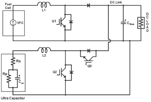
Fig. 1. Interface converter topology.
The FC and ultracapacitor are connected to the same dc bus through the appropriate converter.
The FC is connected to the dc bus by a step-up converter. The ultracapacitor is connected to the dc bus through a bidirec-tional dc–dc converter, which can operate in buck and boost modes. The bidirectional dc–dc converter should operate in suitable mode according to the condition of the ultracapacitor and the FC so that each part of the system can cooperate well with high reliability, high efficiency, and good dynamic characteristics.
According to the previous work in [4], the FC had a 42-V nominal voltage. The bus voltage was 100 V. During start-up and transient conditions, the ultracapacitor will supply the load. When the power generated by the FC was more than the power needed for the load, and also during regenerative braking, the converters charged the ultracapacitor. The ultracapacitor has 165-F capacity, and it can be charged up to 48 V. The schematic of the whole system is shown in Fig. 1.
III. DYNAMICEVOLUTIONCONTROLDESIGN
Dynamic evolution control has been utilized in [4] and [5]. The basic idea of dynamic evolution control is to reduce the error state by forcing the error state to follow a specific path, which ensures that the error state goes to zero as time goes by. This specific path is named dynamic evolution path. By using dynamic evolution control, the dynamic characteristic of the system is forced to make evolution by following an evolution path. With the selected evolution path being an ex-ponential function, as shown in Fig. 2, the value of the dynamic characteristic of the system will decrease exponentially to zero by
Y =YO·e−mt (1)
whereY is the dynamic characteristic of the system,YOis the
initial value ofY, andmis a design parameter specifying the rate of evolution.
The dynamic evolution function of this controller can be written as
dY
dt +mY = 0, m >0. (2)
Fig. 2. Dynamic evolution path.
In order to obtain the control law that guarantees that the dynamic characteristic of the system decreases to zero by following the evolution path, the synthesis process is done.
In a dc–dc power converter, this control law corresponds to the duty-cycle equation of the converter. This duty-cycle equation α(vO, Vg, iL)representsαas a function of the state
(vO, Vg, and iL). The duty-cycle equation α(vO, Vg, iL) is
obtained by analyzing and substituting the dynamic equation of the converter system into the dynamic evolution function (2).
IV. SYNTHESIS OF THEBIDIRECTIONALDC–DC CONVERTERCONTROLLER
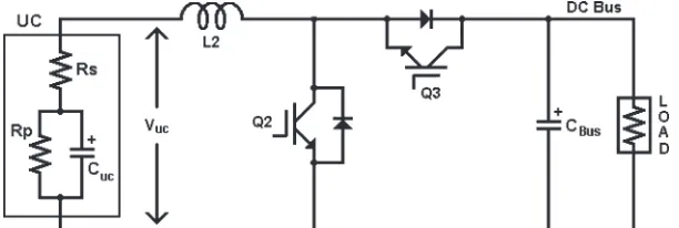
A schematic diagram of the bidirectional dc–dc converter, which is used for interfacing the ultracapacitor to the bus, is shown in Fig. 3. The converter can be operated in two modes of operation, namely, boost and buck. During boost operation, the converter operates as a boost converter, and the power flows from the ultracapacitor to dc bus. During buck operation, the converter operates as a buck converter, and the power flows from the dc bus to the ultracapacitor.
Because the power converter switches are operated in a complementary way, it is sufficient to find out the control law in the boost mode of operation only. In fact, the duty cycle of the upper switch, which is responsible for the buck operation, is(1−α).
Based on the state-space average model, the voltage and current dynamics of the boost mode of operation are given by
VUC=L
whereLis the inductance,C is the capacitance,Ris the load resistance,VUCis the ultracapacitor voltage,iLis the inductor
current,vOis the output voltage, andαis the duty cycle.
Rearranging (3), the output voltage of the converter can be written as
vO=VUC+vO.α−L diL
The dynamic evolution synthesis of the controller begins by defining the state error function (Y). In power-electronic application,Y can be selected as a function of error voltage or error current. By referring to the previous work [4], the selected
Y is a linear function of error voltage
Y =k·verr (6)
where kis a positive coefficient and verr is the error voltage
(verr=Vref−vO).
Substituting (6) into (2) yields
k· dverr
dt +m·k·verr= 0
k· dverr
dt + (m·k−1)·verr+Vref =vO. (7)
Directly substituting the converter voltage outputvOfrom (5)
into (7) gives
k· dverr
dt +(m·k−1)·verr+Vref=VUC+vO·α− diL
dt . (8)
Solving forα, the obtained duty cycleαis given by
α= k dverr
dt + (mk−1)verr+LdidtL +Vref−VUC
vO
. (9) The expression for duty cycleαis the control action for the converter controller. Rearranging duty-cycle equation (9), duty cycleαcan be written as
α=Vref−VUC
vO
+(mk−1)
vO
verr+
k vO
dverr
dt + L vO
diL
dt . (10)
It is interesting to note that the control law in (10) consists of four distinct parts. The first part is the feedforward term(Vref− VUC)/vO, which is calculated based on the duty cycle at the
previous sampling instant. This term compensates for variations in the input voltages.
The second and third terms are like the proportional and derivative terms of the perturbations in the output voltage, respectively. However, the important fact that makes this con-troller action better than the conventional one is that the gain values of the proportional and derivative terms are not constant. These gains are varying with the output-voltage value. The last term consists of the derivative terms of the inductor current. The gain of this term is also varying with the output-voltage value.
From (9), we can see that the input voltage, output voltage, and inductor current are involved in the control output. The
Fig. 4. Error converging speed with differentmvalues.
Fig. 5. FC dynamic model.
advantage is that dynamic evolution control can compensate all variations in the input and output voltages, as well as the change of inductor current. It contributes to the better dynamic performance of the controlled system.
In addition, the controller also has a good response in terms of error converging speed. Duty-cycle equation (9) forces state error function Y to make evolution by following (1) and to decrease to zero with a decrease ratem. This means that the larger m will cause the error to decrease faster. The error converging speed with differentmvalues is shown in Fig. 4
V. SIMULATIONRESULT
Fig. 6. Block diagram of duty-cycle calculation.
Fig. 7. Block diagram of PWM generation.
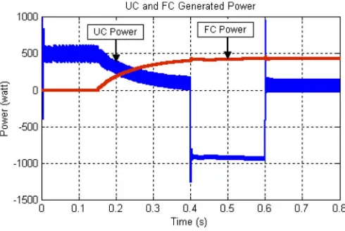
Fig. 8. Demanded power.
evolution controller block diagrams consist of duty-cycle cal-culation and pulsewidth-modulation (PWM) generation block diagrams, as shown in Figs. 6 and 7. Fig. 8 shows the demanded power for certain periods. The power demand during T1 and T2 is 500 W. During T3, the vehicle is braking, and during T4, the power demand is 500 W.
The bus and FC voltages are shown in Fig. 9, and the simulation results of iUC,iFC, and io are shown in Fig. 10.
Fig. 11 shows that during the first time span (T1), the FC power is less than the required power, so the ultracapacitor supplies power to the load. In the second time span (T2), the FC power has reached the required level, so the FC starts supplying power to the system. The current of the FC increases slowly to the nominal current, along with the ultracapacitor current that decreases. During the third time span (T3), the vehicle is braking. The ultracapacitor will charge during regenerative braking. In the fourth time span (T4), the FC supplies power to
Fig. 9. FC and dc-bus voltages.
Fig. 10. Simulation results ofIUC,IFC, andIO.
Fig. 11. Power generated by the ultracapacitor and FC.
the load, and the ultracapacitor backs up the difference power between the supplied power from the FC and the load demand power.
Fig. 9 shows that in all time spans, the dc-bus voltage does not drop. The ultracapacitor succeeds in stabilizing the dc bus during the low power of the FC and during the transient time. The power generated by the FC and ultracapacitor is shown in Fig. 11.
Fig. 12. Hardware prototype for implementation.
Fig. 13. Experimental results of the ultracapacitor, FC, and dc-bus voltages. (Ch1) Ultracapacitor voltage. (Ch3) DC-bus voltage. (Ch4) FC voltage.
the FC-powered automobile to accelerate rapidly and also re-spond to sudden changes in load conditions.
VI. EXPERIMENTALRESULT
To validate the effectiveness of the controller, a hardware prototype of the system is realized, as shown in Fig. 12. The FC part is emulated by a programmable dc power supply. The ul-tracapacitor energy storage is a BOOSTCAP BMOD0165E48B ultracapacitor module (165 F, 48 V, andESR= 7mΩ) from Maxwell Technologies.
A DSP-based dynamic evolution controller has been im-plemented. The Spectrum Digital TMS320F2812 eZdsp board is used for a flexible and rapid prototyping design approach. The TMS320F2812 eZdsp board is employed to implement the dynamic evolution control and the PWM signal generator.
The experimental results are shown in Figs. 13 and 14. Fig. 13 shows the waveforms of the ultracapacitor, FC, and dc-bus voltages when the FC starts. The FC voltage was increased slowly to reach the nominal voltage level in 3 s.
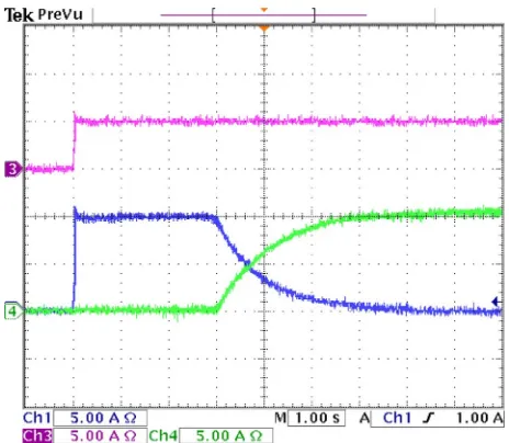
Fig. 14. Experimental results of the ultracapacitor, FC, and load currents. (Ch1) Ultracapacitor current. (Ch3) Load current. (Ch4) FC current.
At the first 3 s, the FC has no enough power. At this interval time, the ultracapacitor supplies power to the bus and maintains the dc-bus voltage to the reference level. It can be seen from Fig. 14 that the ultracapacitor current suddenly goes to 10 A, as well as the supply current at the first 3 s of time. When the FC starts to supply power to the dc bus, the current of the FC increases up to 10 A, and the ultracapacitor current decreases to the zero level according to the increase of the FC current.
VII. CONCLUSION
A new control method for a bidirectional dc–dc converter, which is used for interfacing ultracapacitor energy storage to an FC system, has been presented in this paper. This paper has shown that using a bidirectional converter as an interface between an FC and an ultracapacitor gives better control over FC voltage during transients.
REFERENCES
[1] M. Amirabadi and S. Farhangi, “Fuzzy control of a hybrid power source for fuel cell electric vehicle using regenerative braking ultracapacitor,” in
Proc. Power Electron. Motion Control Conf., Aug. 2006, pp. 1389–1394. [2] A. Drolia, P. Jose, and N. Mohan, “An approach to connect ultracapacitor to fuel cell powered electric vehicle and emulating fuel cell electrical characteristics using switched mode converter,” inProc. IEEE IECON, Nov. 2003, pp. 897–901.
[3] P. Thounthong, S. Rael, and B. Davat, “Control strategy of fuel cell and supercapacitors association for a distributed generation system,”IEEE Trans. Ind. Electron., vol. 54, no. 6, pp. 3225–3233, Dec. 2007. [4] A. S. Samosir and A. H. M. Yatim, “Dynamic evolution control of
bidi-rectional DC–DC converter for interfacing ultracapacitor energy storage to fuel cell electric vehicle system,” inProc. AUPEC Conf., Dec. 2008, pp. 1–6.
[5] A. S. Samosir and A. H. M. Yatim, “Implementation of new control method based on dynamic evolution control with linear evolution path for boost DC–DC converter,” inProc. PECON, Dec. 2008, pp. 213–218. [6] A. S. Samosir and A. H. M. Yatim, “Implementation of new control
method based on dynamic evolution control for DC–DC power converter,”
Int. Rev. Elect. Eng. J., vol. 4, no. 1, pp. 1–6, Feb. 2009.
[7] B. YuWen, D. Zhu, and X. Jiang, “Performance optimization control of the fuel cells electric vehicle driving system,” inProc. Int. Power-Con, 2002, pp. 149–152.
[8] K. Jin, X. Ruan, M. Yang, and M. Xu, “A hybrid fuel cell power system,”
[13] M. H. Todorovic, L. Palma, and P. N. Enjeti, “Design of a wide input range DC–DC converter with a robust power control scheme suitable for fuel cell power conversion,”IEEE Trans. Ind. Electron., vol. 55, no. 3, pp. 1247–1255, Mar. 2008.
[14] M. Ortuzar, J. Moreno, and J. Dixon, “Ultracapacitor-based auxiliary energy system for an electric vehicle: Implementation and evaluation,”
IEEE Trans. Ind. Electron., vol. 54, no. 4, pp. 2147–2156, Aug. 2007. [15] M. Tekin, D. Hissel, M. C. Pera, and J. M. Kauffmann,
“Energy-management strategy for embedded fuel-cell systems using fuzzy logic,”
IEEE Trans. Ind. Electron., vol. 54, no. 1, pp. 595–603, Feb. 2007. [16] A. F. Burke, “Batteries and ultracapacitors for electric, hybrid, and fuel
cell vehicles,”Proc. IEEE, vol. 95, no. 4, pp. 806–820, Apr. 2007. [17] J. Moreno, M. E. Ortuzar, and J. Dixon, “Energy-management system
for a hybrid electric vehicle, using ultracapacitors and neural networks,”
IEEE Trans. Ind. Electron., vol. 53, no. 2, pp. 614–623, Apr. 2006. [18] S. Choe, J. Ahn, J. Lee, and S. Baek, “Dynamic simulator for a PEM
fuel cell system with a PWM DC/DC converter,”IEEE Trans. Energy Convers., vol. 23, no. 2, pp. 669–680, Jun. 2008.
[19] X. Yu, M. R. Starke, L. M. Tolbert, and B. Ozpineci, “Fuel cell power conditioning for electric power applications: A summary,”IET Elect. Power Appl., vol. 1, no. 5, pp. 643–656, Sep. 2007.
[20] W. Friede, S. Rael, and B. Davat, “Mathematical model and characteri-zation of the transient behavior of a PEM fuel cell,”IEEE Trans. Power Electron., vol. 19, no. 5, pp. 1234–1241, Sep. 2004.
[21] J. M. Lee and B. H. Cho, “A dynamic model of a PEM fuel cell system,” inProc. APEC, Feb. 2009, pp. 720–724.
[22] A. Gebregergis, P. Pillay, D. Bhatacharyya, and R. Rengaswemy, “Solid oxide fuel cell modeling,”IEEE Trans. Ind. Electron., vol. 56, no. 1, pp. 139–148, Jan. 2009.
[23] C. Wang, M. H. Nehrir, and S. R. Shaw, “Dynamic models and model val-idation for PEM fuel cells using electrical circuits,”IEEE Trans. Energy Convers., vol. 20, no. 2, pp. 442–451, Jun. 2005.
[24] K. P. Adzakpa, K. Agbossou, Y. Dube, M. Dostie, M. Fournier, and A. Poulin, “PEM fuel cells modeling and analysis through current and voltage transient behaviors,”IEEE Trans. Energy Convers., vol. 23, no. 2, pp. 581–591, Jun. 2008.
Lampung, Indonesia. His areas of research interest include renewable energy, control techniques, and the application of power converters.
Abdul Halim Mohamed Yatim (M’89–SM’01) received the B.Sc. degree in electrical and elec-tronic engineering from Portsmouth Polytechnic, Portsmouth, U.K., in 1981 and the M.Sc. and Ph.D. degrees in power electronics from the University of Bradford, Bradford, U.K., in 1984 and 1990, respectively.
Since 1982, he has been a Faculty Member with the Department of Energy Conversion, Fac-ulty of Electrical Engineering, Universiti Teknologi Malaysia, Johor Bahru, Malaysia, where he was ap-pointed as Dean of the Faculty of Biomedical Engineering in September 2009 and is currently a Senior Professor. His areas of interest include power quality, renewable/alternative energy, and power-electronic application and drives. He was a Commonwealth Fellow during 1994–1995 at Heriot–Watt University, Edinburgh, U.K., and a Visiting Scholar at the Center for Power Electron-ics Systems, Virginia Polytechnic Institute and State University, Blacksburg, in 1993.