ISSN: 1693-6930
accredited by DGHE (DIKTI), Decree No: 51/Dikti/Kep/2010 183
Dynamic Evolution Control for Fuel Cell DC-DC
Converter
Ahmad Saudi Samosir*1, Tole Sutikno2, Abdul Halim Mohd Yatim3
1
Department of Electrical Engineering, Universitas Lampung
Jln. Prof Sumantri Brojonegoro, Bandar Lampung, 35145, Indonesia, Ph./Fax: +62 721-701609/702767 2
Department of Electrical Engineering, Universitas Ahmad Dahlan (UAD)
Jln. Prof. Soepomo, Janturan, Yogyakarta 55164, Indonesia, Ph./Fax: +62 274-379418/381523 3
Department of Energy Conversion, Universiti Teknologi Malaysia (UTM) FKE-UTM, Skudai, 81310 Johor, Malaysia, Ph./Fax: +607-5535200/5566272
e-mail: [email protected]*1, [email protected], [email protected]
Abstrak
Sel bahan bakar adalah sumber energi alternatif baru yang memiliki prospek yang baik untuk pembangkitan energi listrik terdistribusi dan aplikasi kendaraan listrik. Namun, sel bahan bakar mempunyai respon yang lambat disebabkan respon elektrodinamik dan termodinakmik internal. Untuk mengoptimasi kinerja dari sistem sel bahan bakar, diperlukan sebuah konverter DC ke DC untul sel bahan bakar dengan pengendali yang sesuai yang dapat meregulasi aliran daya dan secara otomatik mengatur tegangan keluaran konverter. Paper ini mengusulkan sebuah teknik kendali baru untuk konverter daya DC ke DC sel bahan bakar. Dilakukan desain dari metoda kontrol yang diusulkan. Sebuah pendekatan baru untuk sintesa pengendali konverter berbasis teori pengendali evolusi dinamik di paparkan. Pada paper ini didiskusikan contoh sintesa pengendali konverter DC ke DC tipe boost. Kinerja dari pengendali evolusi dinamik yang diusulkan disimulasikan menggunakan Matlab-Simulink untuk kondisi perubahan beban. Hasil simulasi menunjukkan bahwa teknik yang diusulkan adalah berkemampuan untuk mengendalikan konverter DC ke DC sel bahan bakar.
Kata kunci: boost, konverter DC ke DC, pengendali evolusi dinamik, sel bahan bakar
Abstract
Fuel cells are new alternative energy resource that has a great promise for distributed generation and electric vehicle application. However, fuel cells have a slow response due to their slow internal electromechanical and thermodynamic response. To optimize the fuel cell system performance, a fuel cell DC-DC converter with an appropriate controller which can regulate the power flow and automatically adjust the converter output voltage is needed. This paper proposes a new control technique for fuel cell DC-DC power converter. Design of the proposed control method for fuel cell DC-DC power converter is provided. A new approach for converter controllers synthesis based on dynamic evolution control theory is presented. In this paper, synthesis example of boost DC-DC converter is discussed. Performance of the proposed dynamic evolution control under step load variation condition is simulated under Matlab-Simulink environment. Simulation results show that the proposed techniques are capable for controlling fuel cell DC-DC converter.
Keywords: boost, DC-DC Converter, dynamic evolution control, fuel cell
1. Introduction
production technology, the fuel cells have a wider range of applications. Their potential application ranges from systems of a few watts to megawatts.
Among the various types of fuel cell, Proton exchange membrane (PEM) fuel cell is the most popular. PEM fuel cells show great promise for use in distributed generation electric vehicle applications. Compared with other distributed generation technologies, such as wind and photovoltaic (PV) generation, PEM fuel cells have the advantage that they can be placed anywhere within the distribution system, without geographic limitations, to achieve the best performance. In electric vehicles application, the increased desire for vehicles with less emission has made PEM fuel cells attractive for vehicular applications since they are essentially no pollutants emission and have high-power density and quick start [5-8].
PEM fuel cells are good energy sources to provide reliable power at steady state, but they have a slow response. This is mainly due to their slow internal electrochemical and thermodynamic responses [9-11]. In order to optimize the fuel cell system performance, a fuel cell DC-DC converters is needed to develop for various applications. Another important issue is the need for appropriate control of fuel cell DC-DC converter which can regulate the power flow and automatically adjust output voltage of the converters to avoid rapid load voltage variations, which may lead to a reduction of the power quality of the system.
Based on the above issues, this paper proposes an approach for fuel cell DC-DC converter controller using dynamic evolution control. The controllers synthesis based on dynamic evolution control theory is presented. The dynamic evolution control exploits the non-linearity and time-varying properties of the system to make it a superior controller. A comprehensive simulation analysis was conducted to verify the performance of the controller. The steady-state and transient response of the system is investigated.
2. Dynamic Evolution Controller Design for Fuel Cell DC-DC Converter 2.1 Fuel Cell DC-DC Converter System Model
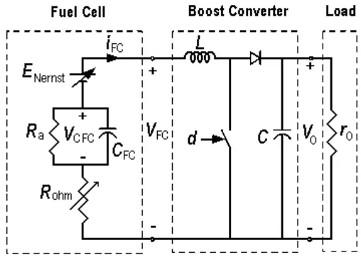
A valid model for fuel cell and DC-DC Converter is introduced in [12]. Circuit of this model is illustrated in Figure 1. The circuits consist of a fuel cell generator, the boost DC-DC converter and load. Using boost DC-DC converter, the provided output voltage to the load can be regulated to the required voltage. The output voltage can be controlled by change the duty cycle (d) of boost DC-DC converter.
Figure 1. Circuit model of Fuel Cell and DC-DC Converter
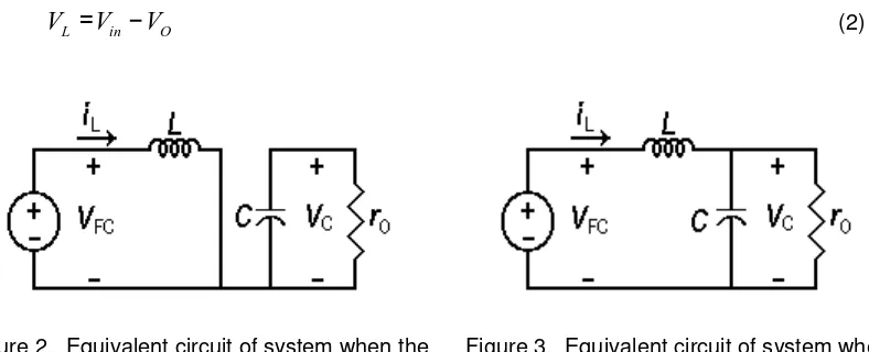
circuit of system when the switch is closed. Kirchhoff’s voltage law around the path containing the Fuel Cell, inductor, and closed switch is
L FC
V
=
V
(1)When the switch is opened, the inductor current cannot change instantly, so the diode becomes forward biased to provide a path for inductor current. Figure 3 shows the equivalent circuit of system when the switch is opened. Assuming that the output voltage VO is a constant,
the voltage across the inductor is
L in O
V
=
V
−
V
(2)Figure 2. Equivalent circuit of system when the switch is closed
Figure 3. Equivalent circuit of system when the switch is opened
The average inductor voltage must be zero for periodic operation. Expressing the average inductor voltage over one switching period,
(
) (1
)(
)
0
L in in O
V
=
D V
− −
D V
−
V
=
(3)Solving for VO yields
1
in O
V
V
D
=
−
(4)The average duty cycle, D, is defined as the time relationship that the switch is on relative to the total switching period.
From (4) at steady state it can be verified that the gain ratio between output and input voltage becomes:
1
1
O
in
V
M
V
D
=
=
−
(5)2.2 Synthesis of Dynamic Evolution Controller for Fuel Cell DC-DC Converter
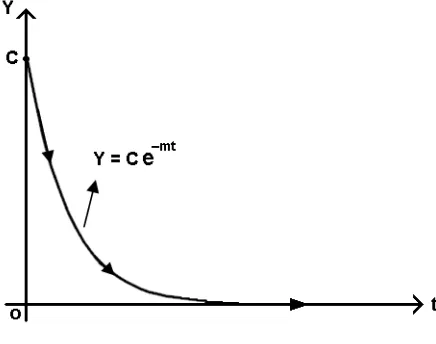
The dynamic evolution control theory has been described in reference [3] and [4]. In dynamic evolution control, the dynamic characteristic of system is forced to make evolution by following an evolution path. With the selected evolution path is an exponential function as shown in Figure 4, the value of the dynamic characteristic of system will decrease exponentially to zero by equation
.
mtwhere, Y is the dynamic characteristic of system, YO is the initial value of Y, and m is a design
parameter specifying the rate of evolution.
Figure 4. Dynamic Evolution path
The dynamic evolution function of this controller can be written as
0,
0
dY
mY
m
dt
+
=
>
(7)Synthesis process is done to obtain the control law that guarantees the dynamic characteristic of system decrease to zero by following the evolution path.
In case fuel cell boost DC-DC converter, this control law corresponds to the duty cycle equation of the converter. This duty cycle equation α(vO,Vg,iL), represents α as a function of the
state vO, Vg and iL. The duty cycle equation α(vO,Vg,iL) is obtained by analyzed and substituted
the dynamic equation of the converter system into the dynamic evolution function (7).
Based on the state-space average model, the dynamics voltage and current of the fuel cell boost DC-DC converter are given by
[
]
. 1
L
FC O
di
V
L
v
d
dt
=
+
−
(8)[
]
. 1
O O
L
dv
v
C
i
d
dt
=
− −
R
(9)where
L
is the inductance,C
the capacitance,R
the load resistance,V
FC the fuel cellvoltage,
i
L the inductor current,v
O the output voltage, andd
the duty cycle, respectively. Rearranging (6), the output voltage of converter can be written as:.
LO FC O
di
v
V
v d
L
dt
=
+
−
(10).
errY
=
k v
(11)the obtained duty cycle
d
is given by:(
1)
err L
err ref FC
O
dv
di
k
mk
v
L
V
V
dt
dt
d
v
+
−
+
+
−
=
(12)The expression for duty cycle α is the control action for the converter controller. Duty cycle
equation (12) forces the state error function Y to make evolution by following equation (6) and decrease to zero with a decrease rate m.
From (12), we can also see that the fuel cell voltage, output voltage and inductor current are involved in control output. The advantage is the dynamic evolution control can compensate all of variation in the fuel cell voltage and output voltage also the change of inductor current. It contributes to the better dynamic performance of the controlled system. Hence the voltage output of converter converges to the converters steady state:
O ref
v
=
V
(13)3. Research Method
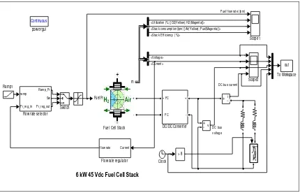
A complete fuel cell and DC-DC converter system with the proposed dynamic evolution control was modelled and simulated using MATLAB/Simulink simulation package. Overall Simulink model of the fuel cell system is shown in Figure 5. In this work, a 65kW, 45V PEM Fuel Cell stack is used as power source. Nominal parameters of the used fuel cell stack in the simulation are given in Table 1.
6 kW 45 Vdc Fuel Cell Stack
Continuous
pow ergui
v +
-out
To Workspace
Switch
Scope2 Scope1
Ramp1
g 1
2
FuelFr
m
+
-m
+
-FuelFr
Fuel Cell Stack ramp
Fr_reg_in Ramp_Fr
Sw
Fr_reg_out
Flow rate selector
Current f low rate
Flow rate regulator
+ FC
- FC +
-DC/DC Converter
i +
-> 8
Clock <Voltage> <Current>
DC bus v oltage
DC bus current <Utilization (%) [O2(Yellow); H2(Magenta)]>
<Stack Ef f iciency (%)>
<Stack consumption (lpm) [Air(Yellow); Fuel(Magenta)]>
Fuel f low rate (lpm)
Table 1. Fuel Cell Nominal Parameters
Parameter Value
Stack Power: Nominal Maximal
5998.5 W 8325 W Fuel Cell Resistance 0.07833 ohms Nerst voltage of one cell (En) 1.1288 V Nominal Utilization:
Hydrogen (H2) Oxidant (O2)
99.56 % 59.3 % Nominal Consumption:
Fuel Air
60.38 slpm 143.7 slpm
Exchange current 0.29197 A
Exchange coeficient 0.60645
0 50 100 150 200
30 40 50 60 70
(225,37) Stack voltage vs current
V
o
lt
a
g
e
(
V
)
Current(A)
0 50 100 150 200
0 2 4 6 8 10
(8.325kW) Stack power vs current
P
o
w
e
r
(k
W
)
[image:6.595.147.463.257.487.2]Current(A)
Figure 6. V-I and P-I Characteristic of the used Fuel Cell
0 2 4 6 8 10 12 14 16
10 20 30 40 50
Demanded Load Current
time (t)
C
u
rr
e
n
t
(A
)
[image:6.595.138.454.542.707.2]0 2 4 6 8 10 12 14 16 45
50 55 60 65
F
u
e
l
C
e
ll
V
o
lt
a
g
e
Fuel Cell Voltage and Current
0 2 4 6 8 10 12 14 16
-50 0 50 100 150
time (s)
F
u
e
l
C
e
ll
C
u
rr
e
n
t
Figure 8. Voltage and Current of Fuel Cell
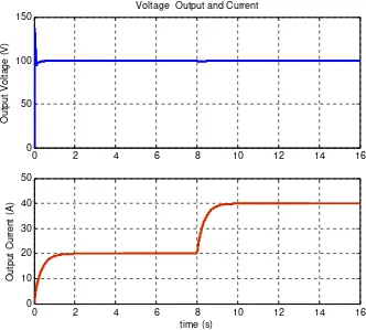
0 2 4 6 8 10 12 14 16
0 50 100 150
Voltage Output and Current
O
u
tp
u
t
V
o
lt
a
g
e
(
V
)
0 2 4 6 8 10 12 14 16
0 10 20 30 40 50
time (s)
O
u
tp
u
t
C
u
rr
e
n
t
(A
)
In this work, the performace of fuel cell converter system is tested under step load change condition. This test aims to see the ability of the fuel cell converter to regulate output voltage during a sudden load change condition. Here the situation where the initial load is set to 20A. At time is 8 second, the load demad is sudently changes to 40A. This load change condition is done by closing the load switch on the simulation model. The control goal is to regulate output voltage, VO=100V. The reference voltage is set at 100V during the operation.
4. Simulation Result
A comprehensive simulation analysis was conducted to verify the fuel cell DC-DC converter system performance. The performance of dynamic evolution control under step load condition is tested through simulation by using MATLAB SIMULINK. The V-I and P-I characteristics of the used fuel cell are shown in Figure 6, whereas the demanded load current for a period of time is in Figure 7. The simulation waveform of fuel cell voltage and current are shown in Figure 8, while the output voltage and load current are shown in Figure 9.
The simulation waveform shown that when the step load changes condition occured, the fuel cell and load current are increase, but the DC-DC converter output voltage is still maintain in the same level. This condition indicates that the controllers accomplish to regulate the converter output voltage keep on steady-state at 100V reference. In the previous research [3], [4], the controller also has successfully controlled bidirectional DC-DC converter for interfacing ultracapacitor energy storage to fuel cell system. Therefore, the controller can be employed as alternative control for DC-DC converter.
5. Conclusion
This paper presents a dynamic evolution control for fuel cell DC-DC converter. The performance of dynamic evolution control under step load variation condition has been tested. From the simulation that have been done, the dynamic evolution control shown the advantages such as fast response and good transient performance. Simulation results show the dynamic evolution control law is insensitive to the input and parameter variations. The controller accomplishes to regulate the converter output voltage keep on steady-state at 100V reference.
References
[1]. Dwari S, Parsa L. A Novel High Efficiency High Power Interleaved Coupled-Inductor Boost DC-DC Converter for Hybrid and Fuel Cell Electric Vehicle. Vehicle Power and Propulsion Conference. 2007; 1: 399-404.
[2]. Xu H, Wen X, Qiao E, Guo X, Kong L. High Power Interleaved Boost Converter in Fuel Cell Hybrid Electric Vehicle. IEEE International Conference on Electric Machines and Drives. 2005; 1:1814-1819. [3]. Samosir AS, Yatim AHM. Dynamic evolution control of bidirectional DC-DC converter for interfacing ultracapacitor energy storage to Fuel Cell Electric Vehicle system. Power Engineering Conference. Australia. 2008; 1:1-6.
[4]. Samosir AS, Yatim AHM. Implementation of Dynamic Evolution Control of Bidirectional DC-DC Converter for Interfacing Ultracapacitor Energy Storage to Fuel Cell System. IEEE Transactions on Industrial Electronics. 2010; 57(10): 3468-3473.
[5]. Maggio G, Recupero V, Pino L. Modeling polymer electrolyte fuel cells: an innovative approach.
Journal of Power Sources. 2001; 101(2): 275–286.
[6]. Friede W, Rael S, Davat B. Mathematical model and characterization of the transient behaviour of a PEM fuel cell. IEEE Transactions on Power Electronics. 2004; (9): 1234–1241.
[7]. Lee JM, Cho BH. A dynamic Model of a PEM Fuel Cell System. APEC 2009 conference, 2009; 1: 720–724.
[8]. Hamelin J, Agbossou K, Laperrière A, Laurencelle F, Bose TK. Dynamic behavior of a PEM fuel cell stack for stationary applications. International Journal Hydrogen Energy. 2001; 26(6): 625–629. [9]. Thounthong P, Rael S, Davat B. Control Strategy of Fuel Cell and Supercapacitors Association for a
Distributed Generation System. Transactions on Industrial Electronics. 2007; (12): 3225–3233. [10]. Nehrir M H, Wang C, Shaw S R. Fuel cells: promising devices for distributed generation. IEEE Power
Energy Magazine. 2006; 4(1): 47–53
[11]. Samosir A S, Anwari M, Yatim A H M. A simple PEM Fuel Cell Emulator using Electrical Circuit model. International Power and Energy Conference. Singapore. 2010; 1: 881–885.