EXPLORING BIM FOR OPERATIONAL INTEGRATED ASSET MANAGEMENT–
A PRELIMINARY STUDY UTILISING REAL-WORLD INFRASTRUCTURE DATA
G.A.Boyesa∗,C.Ellula
,D.Irwinb
aDept.ofCivil,Environmental&GeomaticEngineering,UCL,GowerStreet,London,WC1E6BT,UK
bCrossrailLtd.Floor28,25CanadaSquare,CanaryWharf,London,E145LQ,UK
KEY WORDS:BIM, GIS, Integration, Rail, Infrastructure, Asset Management, Handover
ABSTRACT:
The use of 3D information models within collaborative working environments and the practice of Building Information Modelling (BIM) are becoming more commonplace within infrastructure projects. Currently used predominantly during the design and con-struction phase, the use of BIM is capable in theory of providing the information at handover that will satisfy the Asset Informa-tion Requirements (AIRs) of the future Infrastructure Manager (IM). One particular challenge is establishing a link between existing construction-centric information and the asset-centric information needed for future operations. Crossrail, a project to build a new high-frequency railway underneath London, is handling many such challenges as they prepare to handover their digital information to the future operator, in particular the need to provide a two-way link between a federated 3D CAD model and an object-relational Asset Information Management System (AIMS). This paper focusses on the potential for improved Asset Management (AM) by integrating BIM and GIS systems and practices, and makes a preliminary report on how 3D spatial queries can be used to establish a two-way relational link between two information systems (3D geometry and asset lists), as well as the challenges being overcome to transform the data to be suitable for AM.
1. INTRODUCTION
Over the past decade, Architectural, Engineering and Construc-tion (AEC) sectors in many countries have seen an accelerated uptake in the use of Building Information Modelling (BIM). The philosophy of BIM is that it provides a collaborative working en-vironment to share intelligent, structured information attached to a 3D information model (BIM Task Group, 2014). The driving force behind the adoption of BIM is the eager expectation that digital technologies will foster more efficient collaboration be-tween project stakeholders. For example, in 2015 the UK govern-ment made a saving of£840m within its constructions projects, of which a significant proportion is attributed to the adoption of BIM (HM Government, 2015).
As well as the savings being delivered during the design and con-struction phase (referred to as the CAPEX phase), the AEC in-dustry is also anticipating that these efficiencies can be passed on to the Owner/Operator for their additional benefit throughout the operational life of the constructed asset (the OPEX phase). The reasoning behind this is that collaboration between parties leads to a better design which delivers lifelong savings in running costs. Savings are also achieved from the handover of design in-formation to the Owner/Operator that enables them to make wiser decisions with regards to maintenance, modification and disposal.
Crossrail is a complex infrastructure project tasked with design-ing, building and commissioning a high-frequency railway to run across central London. The project includes the construction of 42 km of tunnels and 10 new underground stations that will con-nect into the existing underground railway network. Once com-plete, Crossrail will hand over the track and station infrastructure to Network Rail and Transport for London (TfL), who will take on the legal responsibility of Infrastructure Manager (IM).
∗Corresponding author - [email protected]
The project, approved back in 2007, is not mandated to comply with more recently published BIM specifications. Nevertheless, Crossrail has a vision to lead the way in creating and maintaining data for constructing, operating and maintaining railway infras-tructure and hand over a digital information model that meets the Asset Information Requirements (AIRs) of the future IM. The implementation of these AIRs into the IM Enterprise Asset agement System (EAMS) is in accordance with their Asset Man-agement (AM) strategy. AM is used to ensure that assets con-tribute towards an organisation’s objectives while taking into ac-count cost and risk (ISO, 2014). AM covers activities such as procurement, replacement and amortisation of assets but also in-cludes the management of planned maintenance and defect repair.
Tracking the location of assets is an essential function of AM and Facility Management (FM)1(Solihin, et al., 2016). It is here that the intelligent geometric information found in BIM(usually stored as Computer Aided Design (CAD) data) has great poten-tial. Geographic Information System (GIS) provide many ana-lytical tools which can be used to complement the design and editing functions of BIM/CAD applications. During the design phase, asset geometries are modelled as CAD objects, in paral-lel to asset information being collated in a separate system. The transformation of CAD data into a GIS would allow asset man-agers to directly query spatial information from an EAMS as the object-relational architecture of GIS provides methods for linking asset information and geometry.
This would offer functionality such as “is this asset in the correct space”, or “what other spatial information (e.g. environmental data) exists at this location”. However, before BIM and asset in-formation can be combined in a GIS, it is necessary to export and transform the information and overcome any semantic, schematic and syntactic interoperability issues (Bishr, 1998).
1FM has similar information requirements to AM, but differs as it
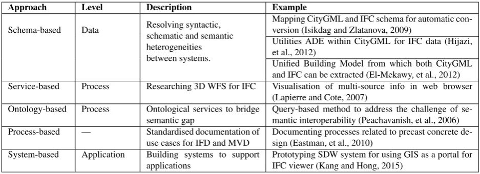
Approach Level Description Example
Schema-based Data Resolving syntactic, schematic and semantic heterogeneities between systems.
Mapping CityGML and IFC schema for automatic con-version (Isikdag and Zlatanova, 2009)
Utilities ADE within CityGML for IFC data (Hijazi, et al., 2012)
Unified Building Model from which both CityGML and IFC can be extracted (El-Mekawy, et al., 2012) Service-based Process Researching 3D WFS for IFC Visualisation of multi-source info in web browser
(Lapierre and Cote, 2007) Ontology-based Process Ontological services to bridge
semantic gap
Query-based method to address the challenge of se-mantic interoperability (Peachavanish, et al., 2006) Process-based — Standardised documentation of
use cases for IFD and MVD
Documenting processes related to precast concrete de-sign (Eastman, et al., 2010)
System-based Application Building systems to support applications
Prototyping SDW system for using GIS as a portal for IFC viewer (Kang and Hong, 2015)
Table 1. Five research approaches and three levels of BIM/GIS integration (Kang and Hong, 2015; Amirebrahimi, et al., 2015)
The Crossrail technical information team are trialling the excha-nge of BIM information from a CAD platform to a GIS platform. This is being done to demonstrate additional ways of using the information through the closer integration of BIM and GIS. This paper will describe some of the challenges in preparing informa-tion for hand over from the construcinforma-tion to operainforma-tion phases and how spatial analysis tools available in GIS applications can be used to provide preliminary solutions to these challenges.
2. UK BIM MANDATE - ASSET MANAGEMENT
In 2011, the UK Government took the decision to advance the implementation of BIM in the UK (Cabinet Office, 2011) and di-rected the creation of a UK BIM Task Group drawing together stakeholders from industry and government. At the same time, the government set a mandate that all central government pro-curement contracts are to include a provision for “the employ-ment and handover of a fully collaborative 3D Building Informa-tion Model with all project and asset informaInforma-tion, documentaInforma-tion and data being electronic as a minimum by 2016”.
As well as providing greater efficiency during the design and con-struction phase, the UK Government expects the collaborative environment to provide a foundation for asset management dur-ing the operational phase (Cabinet Office, 2011). To achieve this aim, the UK BIM Task Group has overseen the publication of a standards documentation that sets out the contractually required level of BIM. Included in this documentation is PAS 1192-3 (BSI, 2014), a Publicly Available Specification (PAS) that publishes a “specification for information management for the operational phase of assets using building information modelling”.
Organisations that implement PAS 1192-3 are required to main-tain an Information Management Process (IMP) covering the life-cycle of their managed assets. The aim of the IMP is to main-tain the integrity of asset information in support of the organisa-tion’s asset management activities. To do this, the AIRs that sup-port an organisation’s asset management activities are set. These AIRs are achieved through the use of an Asset Information Model (AIM) by which all operational information or data is contained or referenced. PAS 1192-3 provides typical examples of infor-mation requirements that an organisation may need, however, the AIRs are ultimately driven by the organisational needs. One par-ticular AIR listed in PAS 1192-3 is asset location, and the PAS suggests the use of spatial referencing or a GIS to achieve this.
PAS 1192-3 states that the AIM shall exist as a federated model, i.e. a model linking distinct component models including a 3D object-based model describing the environment and location of the asset. The AIM may also be linked to other existing enterprise systems, such as EAMS, GIS and spatial analysis toolkits. The PAS specifically states that any interface between the AIM and another system shall be implemented by two-way linking.
Two-way linking provides synchronisation and avoids the cre-ation of duplicated, and potentially conflicting, informcre-ation be-tween two systems. Establishing a link bebe-tween the non-spatial EAMS and the spatial CAD model bestows geometric represen-tation upon information within EAMS. Geometric represenrepresen-tation enables assets to be distinguished from their neighbours and pro-vides visualisation and spatial analysis of assets in the context of their surrounding environment.
3. LITERATURE REVIEW
3.1 Current research conducted into BIM/GIS integration
There have been many papers published in the field of BIM / GIS integration (Fosu, et al., 2015) covering a diverse range of under-standing of how system integration should be achieved. Kang and Hong (2015) classified research in the field of BIM/GIS integra-tion into five approaches: schema-based service-based, ontology-based, process-based and system-based. In a similar manner, Amirebrahimi, et al. (2015) identified three levels of BIM/GIS integration: data level, process level and application level. These classifications are summarised with example literature in Table 1.
3.2 BIM and GIS in Asset Management
Zhang, et al. (2009) consider the use of BIM and GIS applications for data collection and management, data analysis and visualisa-tion in AM. BIM applicavisualisa-tions provide a valuable source of infor-mation, but it is GIS applications that provide the tools that are needed to perform spatial analysis. The ability to use information in disparate systems is conditional upon their interoperability and level of integration (Zhang, et al., 2009).
System Software Object Identified by Spatial Information Description EIMS Bentley eB Structured data &
Documents e.g. Asset tech data sheets in PDF
Document No. e.g. CRL1-XRL- AA-AAA-CR001-00001
No geometry Maybe textual refer-ence in document
Asset documentation tagged by Asset No.
AIMS Bentley eB Asset
e.g. Escalator
Asset No. (Site code + Function code + unique no.) e.g. CR101-AAA-00001
Ref. to Space ID with no geometry. Optional (x,y,z) coord.
CAD ProjectWise/
MicroStation
Geometrical CAD Element e.g. Surface, Solid
Filename & Element ID
Geo-referenced 3D geometry
Federated model aggregating multiple reference files Fire Plan MicroStation Space
e.g. Ticket Hall SID code LIS-1-22
Space ID 2D line drawing
Not geo-referenced
2D plan for required by emergency ser-vices in which every space is identified 2D/3D
GIS
Oracle Spatial/ ArcSDE
Point, line & poly-gon features Multipatch
Object ID Oracle Spatial
SDO GEOMETRY Multipatch BLOB
Crossrail Maps data & Land management information
Trial 3D GIS via web-based portal.
Table 2. Crossrail Information Systems
workflow supporting the handover of asset information that em-phasises the importance of stipulating information requirements at the earliest opportunity.
Kang and Hong (2015) propose a system providing facility man-agers with access to BIM information from a GIS portal. BIM object information is extracted, transformed and loaded to a Spa-tial Data Warehouse (SDW) for visualisation in a GIS using a star schema data structure to link between the BIM model and the SDW model. The geometry of the BIM objects stored in the SDW exists in different levels of detail to support fast visuali-sation in the GIS. Selecting objects in the GIS portal allows the BIM information and geometry to be viewed in a BIM viewer.
Solihin, et al. (2016) considered how the use of federated models had implications on spatial containment which they consider to be a very essential feature of operational BIM. From their inves-tigation, they propose changes to the Industry Foundation Classes (IFC) file format to enable deferred references that enable re-silient object relationships between files.
A consistent theme in the literature is that the handover of BIM in-formation to asset and facility managers is a challenging and ex-pensive process (Thabet, et al., 2016; Solihin, et al., 2016). It is also apparent that BIM and GIS applications need to work to-gether to make better use of the information (Kang and Hong, 2015; Zhang, et al., 2009).
4. CROSSRAIL INFORMATION SYSTEMS
The Crossrail information model is implemented via four sepa-rate systems (Table 2). Bentley Enterprise Bridge (eB) runs the Electronic Information Management System (EIMS) which manages access to all documentation and their supported work-flows related to the project. TheAsset Information Manage-ment System (AIMS)is managed as a subsystem within EIMS enabling documentation to be linked to over a million assets.
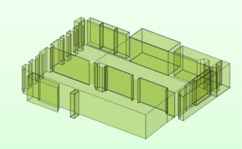
TheBIM/Computer Aided Design (CAD) Systemexists as a federated model as required by BS1192:2007 (BSI, 2007). This
Figure 1. Fire Plan spaces - Station ticket hall
geometric information is stored in the Bentley MicroStation V8 (Select Series 2) format with controlled access managed by ley ProjectWise. BIM extensions (i.e Bentley Architecture, Bent-ley Structural Modeller, BentBent-ley Electrical Systems, etc.) provide BIM authoring tools for creating intelligent BIM objects.
AGeographic Information System (GIS) also exists to sup-port the design, construction and ultimate delivery of the project. These GIS systems are used to disseminate and visualise project information as well as providing administrative and analytical functions. GIS information is stored as SDO GEOMETRY in Oracle Spatial with the exception of ESRI multipatch features which are stored as a Binary Large Object (BLOB). Multipatch is the feature type used for storing 3D solid or surface features in ESRI systems.
The CAD system contains stationfire planswhich are 2D line drawings annotated with floor plan information. These are man-ually converted into polygons which can be extruded using floor-ing and ceilfloor-ing information to provide 2.5D volumetric represen-tation in a 3D GIS Figure 1. Every space in the fire plan has a unique ID which is used by AIMS to specify the asset location.
pub-AIMS Asset Functional
Unit
MicroStation Element ID
ID
Family/ Part XYZ
Space ID
Geometry
Class
Class Level Class Link
Coordinate Link ID Link
Space ID Primary
Functional Unit
Space Link
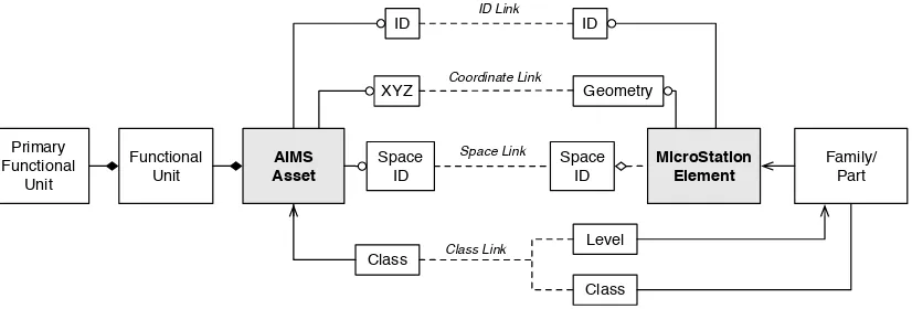
Figure 2. Direct, Spatial and Semantic methods of linking AIMS and CAD objects
lished after the Crossrail system was configured) the Crossrail system holds all information components separately. In addition to the lack of link between AIMS and BIM, the objects within the CAD were created by different sub-contractors in support of design and construction work at an early stage (before the As-set Management Strategy was fully developed), whereas AIMS information is coordinated by a central asset management team.
The CAD objects, created to meet different requirements, have a different scheme of classification to assets in the AIMS. Hence, the correlation of asset classes and CAD classes exists as a com-plexm:nrelationship. A single AIMS asset (e.g. a wall) might be represented in MicroStation as multiple architectural elements (e.g. wall panels). Furthermore, the hierarchy of how objects are aggregated in the CAD model does not always correlate with the hierarchy in AIMS. Overcoming this challenge (them:nlink between asset information and geometry) is fundamental to en-abling the potential of operational BIM.
5. STEP 1 - EXAMINING OPTION FOR LINKING
To satisfy the requirements of PAS 1192-3, as well as to offer the potential for an integrated Asset Management System to the IM, the Crossrail technical information team identified four methods for linking asset items in AIMS with geometry elements (Fig-ure 2). The suitability of each method was considered in terms of the time required to input links into the system, the link quality, and potential for implementation.
ID Link— This method implements an explicit link between the Identifiers (IDs) of AIMS assets and MicroStation elements. The work-hours required to input a defined link for every AIMS asset is prohibitively expensive, given that there are millions of assets. Crossrail had requested the software provider to develop a customised application to facilitate this work but technical and commercial issues related to linking groups of elements across different files prevented its development. Additionally, such a link does not possess referential integrity and is susceptible to be broken should the element ID change.
Coordinate Link— This method would provide an explicit spa-tial relationship between a fixed point on the asset and the ge-ometry of the related MicroStation element, and involves tagging each asset in AIMS with an (x,y,z) coordinate to its approximate location in London Survey Grid as it is commissioned/inspected. The inputting of point coordinates representing each asset was trialled by the Crossrail technical team but was abandoned due to the unacceptably slow speed of entry. It was also found to be un-reliable due to the introduction of human errors during the input
process and the trial of this method was discontinued in prefer-ence for the next method of linking.
Space Link— The third method is an inferred spatial relation-ship based upon the identity of the space attributed to the asset and the space(s) enclosing the CAD element. However, a long el-ement (e.g. a pipe) may pass through multiple spaces, creating a
1:Mrelationship between asset and space. This1:Mrelationship will need to be catered for if this method is to be remain effec-tive. Populating the AIMS using this method while surveying or commissioning the assets is faster because it is simpler for data inputters to enter the identity of the space according to its name rather than coordinates. As part of the task of creating a 2D fire plan, every space in the infrastructure is allocated a unique ID.
Class Link— The final method is an inferred semantic relation-ship based on schemes of classification. As mentioned in Table 2, the two systems use slightly different schemes of classification between CAD model and the AIMS and so a method of mapping schema needs to be established. By itself, this method is impracti-cal due to the voluminous return of potential links when perform-ing a query. However, used in conjunction with the Space linkperform-ing method, (i.e. the method described above), it is hoped to reduce the number of unsolved links to a sufficiently manageable task for a human asset manager to perform manually. Bymatching the asset descriptionsbetween the two systems as far as possible given their slight differences, and combining this withmatching by identifying assets located in the space spacea better overall match rate will be achieved.
In support of this task of establishing relational links, it is pro-posed to use 3D GIS analysis tools to perform a spatial query on each CAD object to determine the named space in which it is lo-cated. The first step towards this is to extract, transform and load the data from CAD into GIS, and the remainder of this paper will investigate suitable method s for achieving this.
6. STEP 2 - VALIDATING THE SELECTED LINKING OPTION
Given that, as noted above, the Crossrail information system was commissioned in 2009 and uses Bentley MicroStation V8 (Select Series 2), which was released in July 2010, export formats were limited to what was available in this software and it was also nec-essary to explore a number of different export options before one was found that did not result in loss of required information.
Thus, the geometric information was exported from MicroStation in the native .DGN format, via Autodesk .DWG format, via the buildingSMART .IFC format, and via Trimble SketchUp .SKP format. In order to permit subsequent validation of the work-flow, a MicroStation Visual Basic Application (MVBA) script was written to count MicroStation elements in the source file and output element information such as ID, layer and bounding box dimensions to a CSV file.
Once the geometry was exported, FME was used to transform into multipatch features for writing to an ESRI geodatabase to be read into ESRI ArcScene to check the quality of the transforma-tion. The quality of the transformation was assessed by counting the number of features lost, by a visual comparison, by checking that each transformed element could still be identified by its orig-inal MicroStation Element and then forig-inally by testing whether the features were topologically closed. The ArcSceneInside3Dtool was used to validate that a spatial query could be performed to find the 3D space where an object existed. These were created by extruding 2D polygon spaces extracted from floor plans with height data.
7. RESULTS
7.1 Selecting an export option
The ticket hall of the new Liverpool Street station was chosen to compare the export of geometry from MicroStation. The station was chosen because 2.5D polygon spaces had been already been extracted from the 2D CAD fire plans. The geometry was saved in files created from two of the Bentley BIM extensions, Struc-tural Modeller and Electrical Services. The exported geometry contained a variety of geometry shapes including straight-sided blocks, blocks with cut-aways and openings, extruded sections and complex curved geometry.
7.1.1 Reading MicroStation DGN in FME Reading files di-rect from the native MicroStation DGN format is not a viable as FME Workbench is unable to read Surface type elements in this format (Safe Software, 2017). and the majority of elements cre-ated using the MicroStation BIM extensions belong to this type.
7.1.2 Reading Autodesk DWG in FME FME Workbench is capable of reading surfaces in Autodesk’s DWG format which MicroStation is capable of exporting in. However, MicroStation Element IDs are not retained during the export which precludes the ability to trace objects back to the source file. Furthermore, the SmartSolid and SmartSurface element types, used to aggre-gate component elements, are broken down during export, thus multiplying the number of elements being handled. On comple-tion of the transformacomple-tion, a test was carried out on the surfaces to determine their topological correctness. This revealed that over half of the surfaces were not closed, or were found to have other topological defects, such as inverted faces. The work required to heal the geometry was considered to be too great, and research shifted to exploring the IFC format.
7.1.3 Reading Industry Foundation Classes in FME The IFC format is an neutral open source format for BIM information exchange overseen by buildingSMART International. However, attempts to use FME to read models created using Bentley Struc-tural Modeller but then exported as IFC was fraught with diffi-culty as the application would hang whilst attempting to read the geometry. No such problems were experienced opening the same IFC file in Autodesk Revit or Solibiri Model Viewer. IFC files exported from models created using Bentley Electrical Services did not suffer any issues. In all cases, the IFC file can still be read by FME provided only the Bounding Box representation of each element is read instead of the full geometry. This functionality provides the ability to read the semantic information contained within the IFC file.
Attempting to understand the problem, a script was written in Python to use the IfcOpenShell toolbox to parse the IFC file and save each element in its own IFC file. These standalone files were then read in a batch so as to skip the unreadable files. Overall 13 percent of the IFC geometry was found to be unreadable. The ge-ometry elements rejected by FME Workbench were inspected in Solibiri Model Viewer (Solibri, 2017). Looking closely at the ge-ometry reveals polyhedral slivers extending out from the element surface (Figure 3). It seems that attempting to transform these slivers into a 3D GIS format is causing FME to hang. The effect on the model can be observed in Figure 5 which shows gaps in the ceiling of the ticket hall.
7.1.4 Reading Trimble SketchUp in FME This export func-tion saves the model as a single object in the file (which can be de-aggregated in FME). This means the model components are not exported with any reference to the source Element ID needed for a two-way link. However, it is a feature of the SketchUp export function that geometry is tagged with the source file level name and this functionality can be exploited to provide a workaround solution. An MVBA script was written to move each element to a new level named according to the element ID which could be now read in FME.
This geometry-tagging workaround was not always successful, but it is also possible to perform a spatial join on the feature centrepoints with the centrepoints calculated from the bounding boxes read by the MVBA script and written to a CSV file. In the end, 2.1% of the elements exported from Structural Modeller files required human assistance to assign a MicroStation ID. The man-ual tagging is also needed to handle incidents where the SketchUp exporter splits an element into two parts.
7.2 Merging in FME Workbench
The extracted SketchUp geometry was then merged with the se-mantic information exported via the IFC format and written as
MicroStation Elements IFC Elements SketchUp Elements Total (Unfiltered) (Filtered) (Total) (Valid) (Total) (Manual) (Split)
Structural BIM Files
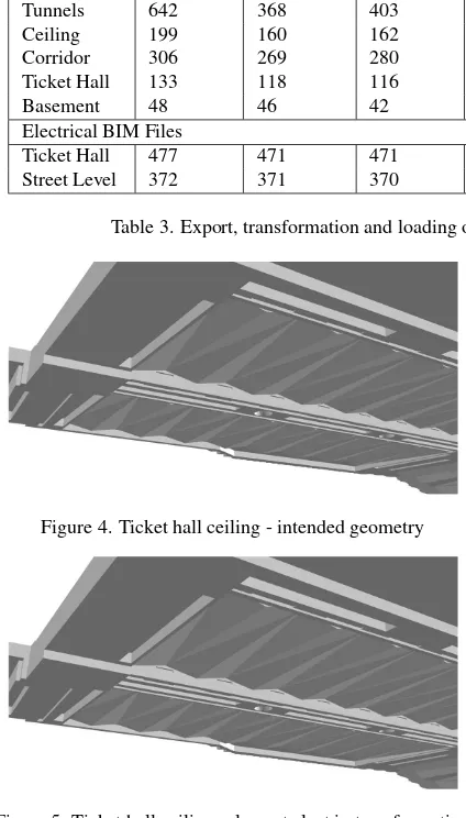
Tunnels 642 368 403 395 260 0 0 260
Ceiling 199 160 162 113 163 10 3 163
Corridor 306 269 280 234 180 0 0 180
Ticket Hall 133 118 116 96 119 6 1 119
Basement 48 46 42 38 46 0 0 46
Electrical BIM Files
Ticket Hall 477 471 471 471 611 — — 471 (IFC)
Street Level 372 371 370 370 547 — — 370 (IFC)
Table 3. Export, transformation and loading of MicroStation Elements via IFC and SketchUp to GIS
Figure 4. Ticket hall ceiling - intended geometry
Figure 5. Ticket hall ceiling- elements lost in transformation
3D multipatch features to an ESRI geodatabase. Each feature was identified with a MicroStation Element ID which, together with the source filename, enables the object to be traced back to the originating element in the source file.
The success of the geometry extraction is recorded in Table 3 for five files exported from Structural Modeller and two files ex-ported from Electrical Services extension. The second column is the elements counted in MicroStation using the MVBA script including features used for marking out and textual annotations. The third column is the elements after filtering to remove text, construction lines, etc. The fourth is elements exported via IFC using the bounding box representation together with the number of elements that could be read by FME. The sixth is the number of elements exported by SketchUp accompanied by the number elements of that required manual tagging. The eight column is the number of elements that the SketchUp exporter split. The final column is the number of multipatch features outputted.
The number of exported features is identical to the number of elements counted by the MVBA script taking into account the splits. This is with the exception of the tunnels file where there are 108 elements unaccounted for. These elements were searched for by their Element ID in MicroStation and they were found to be invisible in the original model. With regard to elements created using the Electrical Services extension, the IFC exporter performs
admirably. Consequently, the workaround described here is only required with respect to the Structural Modeller files.
7.3 Validating in ArcScene
The transformed elements were checked using theIsClosedtool in the ESRI 3D Analyst toolbox. This tool checks whether the topology of the multipatch feature is closed, thus satisfying the principal test for solidness. Although a small percentage of fea-tures were not closed, it was possible to heal them using the En-close Multipatchtool in the 3D Analyst toolbox.
The majority of steps in the workflow were automated using a batch script. However, a small number of exceptions, such as the invisible tunnel elements detailed above, require human input to determine a reason why they were not handled by the FME workspace. The need for manual resolution prevents a fully auto-matic workflow which would otherwise decresease the time taken to extract, transform and load geometry and decrease the chance for human error.
Figure 6 depicts a 3D model of an underground station ticket hall as viewed in ArcScene. As a final test, the usefulness of trans-forming the geometry and loading it into ArcScene was proven through the use of theInside3Dtool. A 2D floor plan with height information was extruded and converted into a multipatch solid. TheInside3Dtool was then successfully used to identify the nam-es of spacnam-es that the transformed featurnam-es are located within.
8. DISCUSSION AND FURTHER WORK
Crossrail is trialling the use of 3D GIS to permit the operational management of asset information, thus yielding further benefits of implementing BIM within the Crossrail project. The work described here demonstrates the potential of GIS and associated spatial analysis tools to overcome the problems identified in Sec-tion 4, i.e. the lack of a link between asset informaSec-tion and lo-cation. This works towards establishing a two-way link between the federated CAD and the non-geospatial AIMS and thus meet the requirement specified in PAS 1192-3 described in Section 2.
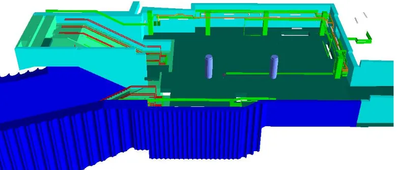
Figure 6. Station ticket hall showing structural, architectural and MEP objects in ESRI ArcScene
The issues described reflect previous work in this field – indeed, the woes of BIM interchange and interoperability are well doc-umented with problems (Pazlar and Turk, 2008; Delfosse, et al., 2012) and exporting data from BIM application to GIS has proved to be complex despite the existence of standard exchange formats such as IFC. In the case of Crossrail, the inability to export geo-metric and semantic information in a single file capable of being loaded into a GIS has required a significant amount of resources in terms of time. Workarounds provide a temporary solution but a large project requires processes that are fully automated. The methods described above go a long way towards achieving this in the context of the Crossrail system, although further extensive testing is required to validate this preliminary approach.
8.1 Examining the Sources of the Conversion Problems
Exporting geometry from CAD into a GIS format requires the conversion of the geometry into Boundary Representation (B-Rep). Straight-sided objects, e.g. a vertical wall, can be identi-cally represented, but curved surfaces, e.g. a tunnel casing, must be discretised and substituted with planar faces. This permanent loss of detail can never be recovered from the transformed geom-etry. By keeping a reference to the source geometry in the origi-nal file, the object can be re-transformed at any time with smaller stroke tolerance (i.e. a higher quality discretisation). However, high fidelity transformation of large objects, such as a tunnel, will be limited by the memory and processing power available.
The reason for FME failing to read IFC geometry can be at-tributed to geometry errors created converting Constructive Solid Geometry (CSG) to B-Rep. CSG elements in MicroStation are retained within the IFC file during export to this format and their conversion to B-Rep is performed in FME. But when the file is exported as a SketchUp file, the CSG is converted to B-Rep within MicroStation. The B-Rep converted by MicroStation does not contain geometry errors and can thus be handled by FME.
The CSG conversion engine in FME Workbench is attempting to convert a degraded geometry following export from its native source. It appears that floating point rounding errors are causing a thin polyhedral sliver to be created which is causing the conver-sion to fail. The CSG converconver-sion engine used in MicroStation to export SketchUp files is not affected, either because it is process-ing source data, or it has built-in resilience to remove the sliver.
The modelling process has created a latent defect that is unde-tectable in the native application but is apparent on export. This
issue could be resolved either by training CAD modellers to avoid error-prone geometry, or developing the application so that the CSG to B-Rep conversion is always performed in the native soft-ware. As the IFC schema supports multiple geometry represen-tations, the option should exist to include B-Rep geometry when exporting IFC from Bentley MicroStation. In the meantime ex-porting geometry via the SketchUp format and merging informa-tion in FME Workbench provides a workable soluinforma-tion.
8.2 Asset Management and Spaces
The final step of this experiment demonstrated the ESRI 3D An-alyst toolbox can be used to identify the location of geometric objects by reference to a named space. This supports the require-ment for matching geometric objects with assets in AIMS as de-scribed in Section 5. The ability to identify features by location in this way also provides the capability to filter a visualisation by reference to spaces, thus enabling the user to remove peripheral features that may be cluttering the visualisation. Also in terms of visualisation, features might be classified using colours related to the space where they belong. This space information can be coupled with asset space information and used to narrow down the potential asset information for each geometry.
The use of a spatial query to determine the space (or spaces) that an object is located may not lead to a match with the same asset that has been located by human interpretation. For instance, if an asset passes through more than one space (e.g. a pipe), the person responsible for marking down the name of the space where that asset is located may decide to use the space where the pipe is predominantly located, or where the pipe starts or ends. This will need to considered when trying to match assets and objects using an automated method. If the name of only one space is used, then the names may differ. If all the spaces that the asset is located are used, then the problem may become unmanageable.
Spaces that are accurately represented may be useful for other applications. For example the use of topological spaces in indoor navigation (Zlatanova, et al., 2016). Perhaps, as also proposed by Kang and Hong (2015) generalisation algorithms can be use on space geometry to provide a framework for supporting simpli-fied visualisation of the indoor environments, thus reducing mem-ory and processor specifcations. More accurately defined spaces might also be used in conjunction with point cloud surveys to detect changes betweenas-designedandas-builtmodels.
8.3 Further challenges
The potential exists to export the geometry and asset informa-tion into a GIS and exploit the spatial analysis opinforma-tions identified by Zhang, et al. (2009) including measuring area and volume, measuring the length of cable runs, and situational awareness of assets. Federated models used in a project Common Data En-vironment (CDE) are difficult for finding the right information due to their folder structure. Transporting the information into a 3D GIS provides a portal to find information in federated models using the architecture proposed by Kang and Hong (2015).
The work described in this paper has mainly focussed on the prac-tical aspects of exporting and transforming geometry. Although the geometry extracted from the CAD is now loaded inside a GIS, there has been no integration with regard to semantics. The next stage in this research project will be to investigate semantic-based and ontological-based approaches as described in Section 3.1.
9. CONCLUSION
The work carried out in this paper adds to the system-based re-search into BIM/GIS integration. It has highlighted the difficul-ties of exporting BIM geometry from a live project into 3D GIS, identifying issues with CSG-based IFC geometry. Workaround methods have been validated for extracting, transforming and loa-ding CAD/BIM geometry into a GIS where it provides an envi-ronment to exploit spatial analysis tools (Zhang, et al., 2009). Further research will continue to investigate whether extruded plans are a suitable representation of the complex spaces of an underground railway. Further research can then be carried out to develop the effectiveness of matching CAD elements and AIMS assets. If this can be accomplished, then the integration of BIM and GIS can be achieved meeting the requirements for a two-way link between systems in PAS 1192-3.
ACKNOWLEDGEMENTS
Work towards this paper has been conducted as part of a PhD stu-dentship supported by Crossrail Ltd. and the EPSRC. The authors thank Crossrail for the provision of BIM data that has provided the necessary realism that is essential for practical research.
References
Amirebrahimi, S., Rajabifard, A., Mendis, P., and Ngo, T., 2015. A Data Model for Integrating GIS and BIM for Assessment and 3D Visualisation of Flood Damage to Building, InCEUR Workshop Proceedings Research@Locate’15, Brisbane, Aus-tralia, 10-12 March 2015, pp. 78-89.
BIM Task Group, 2014. BIM Task Group FAQs, http://www.bimtaskgroup.org/bim-faqs/ (25 July 2014). Bishr, Y., 1998. Overcoming the semantic and other barriers to
GIS interoperability,Int J Geogr Inf Sci12(4), pp. 299-314.
BSI, 2007. BS 1192:2007 Collaborative production of architec-tural, engineering and construction information, BSI. BSI, 2014. PAS 1192-3:2014 : Specification for information
management for the operational phase of assets using building information modelling, British Standards Institution, London. Cabinet Office, 2011 Govt. Construction Strategy, UK Cabinet. Delfosse, V., Schrayen, J., Juchmes, R., and Leclercq, P., 2012.
Some advice for migrating to IFC, In T. Fischer, K. De Biswas, J.J. Ham, R. Naka, & W.X. Huang, eds.,The 17th Interna-tional Conference on Computer-Aided Architectural Design Research in Asia, pp. 265-274.
Eastman, C.M., Jeong, Y.S., Sacks, R., and Kaner, I., 2010. Ex-change Model and ExEx-change Object Concepts for Implemen-tation of National BIM Standards,J Comput Civil Eng24(1), pp. 25-34.
El-Mekawy, M., ¨Ostman, A., and Hijazi, I., 2012. A Unified Building Model for 3D Urban GIS,ISPRS Int Geo-Inf 1(3), pp. 120-145.
Fosu, R., Suprabhas, K., Rathore, Z., and Cory, C., 2015. Integra-tion of Building InformaIntegra-tion Modeling (BIM) and Geographic Information Systems (GIS) – a literature review and future needs, InProc. of the 32nd CIB W78 Conference 2015, 27th-29th October 2015, Eindhoven, The Netherlands, pp. 196-204. Hijazi, I.H., Ehlers, M., and Zlatanova, S., 2012. NIBU: a new ap-proach to representing and analysing interior utility networks within 3D geo-information systems,Int J Digit Earth5(1), pp. 22-42.
HM Government, 2015 Digital Built Britain – Level 3 Strategy. Isikdag, U. and Zlatanova, S., 2009. Towards Defining a
Frame-work for Automatic Generation of Buildings in CityGML Us-ing BuildUs-ing Information Models, In3D Geo-Information Sci-ences, Springer Berlin Heidelberg, Berlin, Heidelberg, pp. 79-96.
ISO, 2014. BS ISO 55000:2014 Asset management: Overview, principles and terminology.
ISO, 2017. ISO 41011:2017 Facility management - Vocabulary, International Standards Organisation.
Kang, T.W. and Hong, C.H., 2015. A study on software archi-tecture for effective BIM/GIS-based facility management data integration,Automation in Construction54, pp. 25-38. Lapierre, A. and Cote, P., 2007. Using Open Web Services for
urban data management: A testbed resulting from an OGC ini-tiative for offering standard CAD/GIS/BIM services, InUrban and Regional Data Management: UDMS 2007 Annual, CRC Press, Boca Raton, Fla.; London.
Pazlar, T. and Turk, Z., 2008. Interoperability in practice: geo-metric data exchance using the IFC standard,IJ of Information Management13, pp. 362-380.
Peachavanish, R., Karimi, H.A., Akinci, B., and Boukamp, F., 2006. An ontological engineering approach for integrating CAD and GIS in support of infrastructure management,Adv Eng Inform20(1), pp. 71-88.
Safe Software, 2017. MicroStation Design Quick Facts, https://docs.safe.com/fme/html/FME Desktop Documentation/ FME ReadersWriters/igds/quick facts igds.htm (27 Apr 17). Solibri, 2017. Solibri Model Viewer - Solibri,
https://www.solibri.com/products/solibri-model-viewer/ (27 April 2017).
Solihin, W., Eastman, C., and Lee, Y.-C., 2016. A framework for fully integrated building information models in a federated environment,Adv Eng Inform30(2), pp. 168-189.
Thabet, W., Lucas, J., and Johnston, S., 2016. A Case Study for Improving BIM-FM Handover for a Large Educational Insti-tution, InConstruction Research Congress 2016 May 31–June 2, 2016, San Juan, Puerto Rico, pp. 2177-2186.
Zhang, X., Arayici, Y., Wu, S.-W., Abbot, C., and Aouad, G., 2009. Integrating BIM and GIS for large scale (building) as-set management: a critical review, InThe 12th International Conference on Civil, Structural and Environmental Engineer-ing ComputEngineer-ing, 1-4 Sep 2009, Funchal, Madeira, Portugal.. Zlatanova, S., Oosterom, P.J M V., Lee, J., Li, K.J., and Lemmen,