Script Program Pengontrol Suhu
#include <LiquidCrystal.h>
LiquidCrystal lcd (13, 12, 11, 10, 9, 8);
#include <SHT1x.h>
#define dataPin 2
#define clockPin 7
SHT1x sht1x(dataPin, clockPin);
int octo4 =3;
int octo3 =4;
int octo2 =5;
int octo1 =6;
void setup() {
// put your setup code here, to run once:
lcd.begin (16,2);
pinMode(octo1, OUTPUT); //deklarasikan sebagai output
pinMode(octo2, OUTPUT); //deklarasikan sebagai output
pinMode(octo3, OUTPUT);
pinMode(octo4, OUTPUT);
Serial.begin(9600);
void loop() {
// put your main code here, to run repeatedly:
float temp_c;
float temp_f;
float humidity;
temp_c = sht1x.readTemperatureC();
temp_f = sht1x.readTemperatureF();
humidity = sht1x.readHumidity();
Serial.print("Temperature: ");
Serial.print(temp_c, DEC);
Serial.print("C / ");
Serial.print(temp_f, DEC);
Serial.print("F. Humidity: ");
Serial.print(humidity);
Serial.println("%");
float suhu;
float kelembaban;
suhu = sht1x.readTemperatureC();
kelembaban = sht1x.readHumidity();
lcd.setCursor(1,0);
lcd.setCursor(13,0);
lcd.print("C");
lcd.setCursor(1,1);
lcd.print("RH : ");
lcd.setCursor(5,1);
lcd.print(kelembaban);
lcd.setCursor(11,1);
lcd.print("%");
delay(50);
float kp_a = 50;
float set_point_a = 28;
float output_a = kp_a * (temp_c - set_point_a);
analogWrite(3,output_a);
if ( temp_c > 28.10 ){
digitalWrite(octo3, HIGH);
}
else{
digitalWrite(octo3, LOW);
}
float kp_b = 50;
float set_point_b = 28;
float output_b = kp_b * (temp_c - set_point_b);
analogWrite(5,output_b);
Version 4.0 – July 2008
(SHT10, SHT11, SHT15)
Humidity and Temperature Sensor
•
Fully calibrated
•
Digital output
•
Low power consumption
•
Excellent long term stability
•
SMD type package – reflow solderable
Drawing of SHT1x sensor packaging, dimensions in mm (1mm = 0.039inch). Sensor label gives “11” for SHT11 as an example. Contacts are assigned as follows: 1:GND, 2:DATA, 3:SCK, 4:VDD.
SHT1x V4 – for which this datasheet applies – features a version 4 Silicon sensor chip. Besides a humidity and a temperature sensor the chip contains an amplifier, A/D converter, OTP memory and a digital interface. V4 sensors can be identified by the alpha=numeric traceability code on the sensor cap – see example “A5Z” code on Figure 1.
While the sensor is made of a CMOS chip the sensor housing consists of an LCP cap with epoxy glob top on an FR4 substrate. The device is fully RoHS and WEEE compliant, thus it is free of Pb, Cd, Hg, Cr(6+), PBB and PBDE.
For sensor trial measurements, for qualification of the sensor or even experimental application of the sensor there is an evaluation kit available including sensor, hard and software to interface with a computer.
For more sophisticated and demanding measurements a multi port evaluation kit is available which allows for parallel application of up to 20 sensors.
SHT1x (including SHT10, SHT11 and SHT15) is Sensirion’s family of surface mountable relative humidity and temperature sensors. The sensors integrate sensor elements plus signal processing on a tiny foot print and provide a fully calibrated digital output. A unique capacitive sensor element is used for measuring relative humidity while temperature is measured by a band=gap sensor. The applied CMOSens® technology guarantees excellent reliability and long term stability. Both sensors are seamlessly coupled to a 14bit analog to digital converter and a serial interface circuit. This results in superior signal quality, a fast response time and insensitivity to external disturbances (EMC).
Each SHT1x is individually calibrated in a precision humidity chamber. The calibration coefficients are programmed into an OTP memory on the chip. These coefficients are used to internally calibrate the signals from the sensors. The 2=wire serial interface and internal voltage regulation allows for easy and fast system integration. The tiny size and low power consumption makes SHT1x the ultimate choice for even the most demanding applications.
SHT1x is supplied in a surface=mountable LCC (Leadless Chip Carrier) which is approved for standard reflow soldering processes. The same sensor is also available with pins (SHT7x) or on flex print (SHTA1).
!"#
sensor opening 2.5±0.1
Datasheet SHT1x
www.sensirion.com Version 4.0 – July 2008 2/11
$
% &'
Parameter Condition min typ max Units
0.4 0.05 0.05 %RH
Resolution1
8 12 12 bit
typical ±4.5 %RH
Accuracy2
SHT10 maximal see Figure 2
typical ±3.0 %RH
Accuracy2
SHT11 maximal see Figure 2
typical ±2.0 %RH
Accuracy2
SHT15 maximal see Figure 2
Repeatability ±0.1 %RH
Replacement fully interchangeable
Hysteresis ±1 %RH
raw data ±3 %RH
Nonlinearity
linearized <<1 %RH
Response time3 τ(63%) 8 s
Operating Range 0 100 %RH
Long term drift4 normal < 0.5 %RH/yr
"
& Maximal RH=accuracy at 25°C per sensor type.
,
-Parameter Condition min typ max Units
Source Voltage 2.4 3.3 5.5 V
sleep 2 5 NW
measuring 3 mW
Power Consumption5
average 150 NW
Communication digital 2=wire interface, see Communication
Storage 10 – 50°C (0 – 125°C peak), 20 – 60%RH
1 The default measurement resolution of is 14bit for temperature and 12bit for
humidity. It can be reduced to 12/8bit by command to status register.
2 Accuracies are tested at Outgoing Quality Control at 25°C (77°F) and 3.3V.
Values exclude hysteresis and non=linearity.
3 Time for reaching 63% of a step function, valid at 25°C and 1 m/s airflow.
."
Parameter Condition min typ max Units
0.04 0.01 0.01 °C
Resolution1
12 14 14 bit
typical ±0.5 °C
Accuracy2
SHT10 maximal see Figure 3
typical ±0.4 °C
Accuracy2
SHT11 maximal see Figure 3
typical ±0.3 °C
Accuracy2
SHT15 maximal see Figure 3
Repeatability ±0.1 °C
Replacement fully interchangeable
=40 123.8 °C
Operating Range
=40 254.9 °F
Response Time6 τ(63%) 5 30 s
Long term drift < 0.04 °C/yr
"
' Maximal T=accuracy per sensor type.
0 - $
Sensor Type Packaging Quantity Order Number
SHT10 Tape & Reel 2000 1=100218=04
Tape & Reel 100 1=100051=04
Tape & Reel 400 1=100098=04
SHT11
Tape & Reel 2000 1=100524=04
Tape & Reel 100 1=100085=04
SHT15
Tape & Reel 400 1=100093=04
4 Value may be higher in environments with high contents of volatile organic
compounds. See Section 1.3 of Users Guide.
5 Values for VDD=5.5V at 25°C, average value at one 12bit measurement
per second.
6 Response time depends on heat capacity of and thermal resistance to
Version 4.0 – July 2008
1
,
!
- $
2 3
Sensor works stable within recommended normal range – see Figure 4. Long term exposures to conditions outside normal range may temporarily offset the RH signal (+3 %RH after 60h). After return to normal range it will slowly return towards calibration state by itself. See Section 1.4. “Reconditioning Procedure” to accelerate eliminating the offset. Prolonged exposure to extreme conditions may accelerate ageing.
. Operating Conditions
2&
For soldering SHT1x standard reflow soldering ovens may be used. The sensor is qualified to withstand soldering profile according to IPC/JEDEC J=STD=020C with peak temperatures at 260°C during up to 40sec including Pb= free assembly in IR/Convection reflow ovens.
" Soldering profile according to JEDEC standard. TP<=
260°C and tP< 40sec for Pb=free assembly. TL< 220°C and tL<
150sec. Ramp=up/down speeds shall be < 5°C/sec.
For soldering in Vapor Phase Reflow (VPR) ovens the peak conditions are limited to TP < 233°C during tP < 60sec and ramp=up/down speeds shall be limited to 10°C/sec. For manual soldering contact time must be limited to 5 seconds at up to 350°C7.
7 233°C = 451°F, 260°C = 500°F, 350°C = 662°F
IMPORTANT: After soldering the devices should be stored at >75%RH for at least 12h to allow the polymer to re= hydrate. Otherwise the sensor may read an offset that slowly disappears if exposed to ambient conditions. In no case, neither after manual nor reflow soldering, a board wash shall be applied. Therefore it is strongly recommended to use “no=clean” solder paste. In case of application with exposure of the sensor to corrosive gases the soldering pads shall be sealed to prevent loose contacts or short cuts.
For the design of the SHT1x footprint it is recommended to use dimensions according to Figure 7. Sensor pads are coated with 35Sm Cu, 5Sm Ni and 0.1Sm Au.
5 Rear side electrodes of sensor, view from top side.
6 Recommended footprint for SHT1x. Values in mm.
2'
-It is of great importance to understand that a humidity sensor is not a normal electronic component and needs to be handled with care. Chemical vapors at high concentration in combination with long exposure times may offset the sensor reading.
For these reasons it is recommended to store the sensors in original packaging including the sealed ESD bag at following conditions: Temperature shall be in the range of 10°C – 50°C (0 – 125°C for limited time) and humidity at 20 – 60%RH (sensors that are not stored in ESD bags).
1.
Datasheet SHT1x
www.sensirion.com Version 4.0 – July 2008 4/11
For sensors that have been removed from the original packaging we recommend to stored them in ESD bags made of PE=HD8.
In manufacturing and transport the sensors shall be prevented of high concentration of chemical solvents and long exposure times. Out=gassing of glues, adhesive tapes and stickers or out=gassing packaging material such as bubble foils, foams, etc. shall be avoided. Manufacturing area shall be well ventilated.
For more detailed information please consult the
document or contact Sensirion.
2. %
As stated above extreme conditions or exposure to solvent vapors may offset the sensor. The following reconditioning procedure may bring the sensor back to calibration state:
Baking: 100 – 105°C at < 5%RH for 10h
Re=Hydration: 20 – 30°C at ~ 75%RH for 12h9.
2" $$
Relative humidity reading strongly depends on
temperature. Therefore, it is essential to keep humidity sensors at the same temperature as the air of which the relative humidity is to be measured. In case of testing or qualification the reference sensor and test sensor must show equal temperature to allow for comparing humidity readings.
If the SHT1x shares a PCB with electronic components that produce heat it should be mounted in a way that prevents heat transfer or keeps it as low as possible. Measures to reduce heat transfer can be ventilation, reduction of copper layers between the SHT1x and the rest of the PCB or milling a slit into the PCB around the sensor (see Figure 8).
7 Top view of example of mounted SHT1x with slits milled into PCB to minimize heat transfer.
Furthermore, there are self=heating effects in case the measurement frequency is too high. Please refer to Section 3.3 for detailed information.
8 For example, please check www.sirel.ch
9 75%RH can conveniently be generated with saturated NaCl solution.
100 – 105°C correspond to 212 – 221°F, 20 – 30°C correspond to 68 – 86°F
25 8
The SHT1x is not light sensitive. Prolonged direct exposure to sunshine or strong UV radiation may age the housing.
26 9
SHT1x does not contain a membrane at the sensor opening. However, a membrane may be added to prevent dirt and droplets from entering the housing and to protect the sensor. It will also reduce peak concentrations of chemical vapors. For optimal response times the air volume behind the membrane must be kept minimal. Sensirion recommends and supplies the SF1 filter cap for optimal IP54 protection (for higher protection – i.e. IP67 = SF1 must be sealed to the PCB with epoxy). Please compare Figure 9.
:Side view of SF1 filter cap mounted between PCB and housing wall. Volume below membrane is kept minimal.
27 1 $ ;
Many materials absorb humidity and will act as a buffer increasing response times and hysteresis. Materials in the vicinity of the sensor must therefore be carefully chosen. Recommended materials are: Any metals, LCP, POM (Delrin), PTFE (Teflon), PE, PEEK, PP, PB, PPS, PSU, PVDF, PVF.
For sealing and gluing (use sparingly): High filled epoxy for electronic packaging (e.g. glob top, underfill), and Silicone. Out=gassing of these materials may also contaminate the SHT1x (see Section 1.3). Therefore try to add the sensor as a last manufacturing step to the assembly, store the assembly well ventilated after manufacturing or bake at >50°C for 24h to outgas contaminants before packing.
2: <
-Carrying the SCK and DATA signal parallel and in close proximity (e.g. in wires) for more than 10cm may result in cross talk and loss of communication. This may be resolved by routing VDD and/or GND between the two data signals and/or using shielded cables. Furthermore, slowing down SCK frequency will possibly improve signal integrity. Power supply pins (VDD, GND) must be decoupled with a 100nF capacitor if wires are used. !"#
housing
PCB
o=ring
Melted plastic pin SHT1x
Datasheet SHT1x
www.sensirion.com Version 4.0 – July 2008 5/11
Capacitor should be placed as close to the sensor as possible. Please see the Application Note “ESD, Latchup and EMC” for more information.
2 ( ) +
ESD immunity is qualified according to MIL STD 883E, method 3015 (Human Body Model at±2 kV).
Latch=up immunity is provided at a force current of
±100mA with Tamb= 80°C according to JEDEC78A. See Application Note “ESD, Latchup and EMC” for more information.
&
-
$
$
4
1 GND Ground
2 DATA Serial Data, bidirectional
3 SCK Serial Clock, input only
4 VDD Source Voltage
NC NC Must be left unconnected
9 SHT1x pin assignment, NC remain floating.
&2 = )> ? ,4 +
The supply voltage of SHT1x must be in the range of 2.4 – 5.5V, recommended supply voltage is 3.3V. Power supply pins Supply Voltage (VDD) and Ground (GND) must be decoupled with a 100 nF capacitor – see Figure 10. The serial interface of the SHT1x is optimized for sensor readout and effective power consumption. The sensor cannot be addressed by I2C protocol, however, the sensor can be connected to an I2C bus without interference with other devices connected to the bus. The controller must switch between the protocols.
( Typical application circuit, including pull up resistor RPand decoupling of VDD and GND by a capacitor.
&2& 0 ) +
SCK is used to synchronize the communication between microcontroller and SHT1x. Since the interface consists of fully static logic there is no minimum SCK frequency.
&2' ) ! !+
The DATA tri=state pin is used to transfer data in and out of the sensor. For sending a command to the sensor, DATA is valid on the rising edge of the serial clock (SCK) and must remain stable while SCK is high. After the falling edge of SCK DATA may be changed. For safe communication DATA valid shall be extended TSUand THO before the rising and after the falling edge of SCK, respectively – see Figure 11. For reading data from the sensor, DATA is valid TV after SCK has gone low and remains valid until the next falling edge of SCK.
To avoid signal contention the microcontroller must only drive DATA low. An external pull=up resistor (e.g. 10kV) is required to pull the signal high – it should be noted that pull=up resistors may be included in I/O circuits of microcontrollers. See Table 2 for detailed I/O characteristic of the sensor.
&2.
The electrical characteristics such as power consumption, low and high level, input and output voltages depend on the supply voltage. Table 2 gives electrical characteristics of SHT1x with the assumption of 5V supply voltage if not stated otherwise. For proper communication with the sensor it is essential to make sure that signal design is strictly within the limits given in Table 3 and Figure 11.
Parameter Conditions min typ max Units
Power supply DC10 2.4 3.3 5.5 V
measuring 0.55 1 mA
average11 2 28 NA
Supply current
sleep 0.3 1.5 NA
Low level output
voltage IOL< 4 mA 0 250 mV
High level output
voltage RP< 25 kV 90% 100% VDD
Low level input
voltage Negative going 0% 20% VDD
High level input
voltage Positive going 80% 100% VDD
Input current on
pads 1 NA
on 4 mA
Output current
Tri=stated (off) 10 20 NA
9 & SHT1x DC characteristics. RP stands for pull up
resistor, while IOLis low level output current.
10Recommended voltage supply for highest accuracy is 3.3V, due to sensor
calibration.
11Minimum value with one measurement of 8 bit accuracy without OTP reload
Datasheet SHT1x
www.sensirion.com Version 4.0 – July 2008 6/11
Timing Diagram, abbreviations are explained in Table 3. Bold DATA line is controlled by the sensor, plain DATA line is controlled by the micro=controller. Both valid times refer to the left SCK toggle.
Parameter Conditions min typ max Units
VDD > 4.5V 0 0.1 5 MHz
FSCK SCK Frequency
VDD < 4.5V 0 0.1 1 MHz
TSCKx SCK hi/low time 100 ns
TR/TF SCK rise/fall time 1 200 * ns
OL = 5pF 3.5 10 20 ns
TFO DATA fall time
OL = 100pF 30 40 200 ns
** TR0is determined by the RP*Cbustime=constant at DATA line
*** TV_maxand TSU_maxdepend on external pull=up resistor (RP) and total bus
line capacitance (Cbus) at DATA line
**** TH0_max< TV– max (TR0, TF0)
9 ' SHT1x I/O signal characteristics, OL stands for Output Load, entities are displayed in Figure 11.
'
=
'2
As a first step the sensor is powered up to chosen supply voltage VDD. The slew rate during power up shall not fall below 1V/ms. After power=up the sensor needs 11ms to get to Sleep State. No commands must be sent before that time.
'2&
To initiate a transmission, a Transmission Start sequence has to be issued. It consists of a lowering of the DATA line while SCK is high, followed by a low pulse on SCK and raising DATA again while SCK is still high – see Figure 12.
& "Transmission Start" sequence
The subsequent command consists of three address bits (only ‘000’ is supported) and five command bits. The SHT1x indicates the proper reception of a command by pulling the DATA pin low (ACK bit) after the falling edge of the 8th SCK clock. The DATA line is released (and goes high) after the falling edge of the 9th SCK clock.
Command Code
Reserved 0000x
(((
% (( (
Read Status Register 00111
Write Status Register 00110
Reserved 0101x=1110x
$ ?resets the interface, clears the status register to default values. Wait minimum 11 ms before next command
(
9 . SHT1x list of commands
'2' $ %
After issuing a measurement command (‘00000101’ for relative humidity, ‘00000011’ for temperature) the controller has to wait for the measurement to complete. This takes a maximum of 20/80/320 ms for a 8/12/14bit measurement. The time varies with the speed of the internal oscillator and can be lower by up to 30%. To signal the completion of a measurement, the SHT1x pulls data line low and enters Idle Mode. The controller must wait for this Data Ready signal before restarting SCK to readout the data. Measurement data is stored until readout, therefore the controller can continue with other tasks and readout at its convenience.
Two bytes of measurement data and one byte of CRC checksum (optional) will then be transmitted. The micro controller must acknowledge each byte by pulling the DATA line low. All values are MSB first, right justified (e.g. the 5thSCK is MSB for a 12bit value, for a 8bit result the first byte is not used).
Communication terminates after the acknowledge bit of the CRC data. If CRC=8 checksum is not used the controller may terminate the communication after the measurement data LSB by keeping ACK high. The device automatically returns to Sleep Mode after measurement and communication are completed.
! !
90% 10%
90% 10% DATA valid read
DATA valid write
Datasheet SHT1x
www.sensirion.com Version 4.0 – July 2008 7/11
Important: To keep self heating below 0.1°C, SHT1x should not be active for more than 10% of the time – e.g. maximum one measurement per second at 12bit accuracy shall be made.
'2. @
If communication with the device is lost the following signal sequence will reset the serial interface: While leaving DATA high, toggle SCK nine or more times – see Figure 13. This must be followed by a Transmission Start sequence preceding the next command. This sequence resets the interface only. The status register preserves its content.
' Connection Reset Sequence
'2" % A7 0
The whole digital transmission is secured by an 8bit checksum. It ensures that any wrong data can be detected and eliminated. As described above this is an additional feature of which may be used or abandoned.
Please consult Application Note “CRC=8 Checksum Calculation” for information on how to calculate the CRC.
%
Some of the advanced functions of the SHT1x such as selecting measurement resolution, end of battery notice or using the heater may be activated by sending a command to the status register. The following section gives a brief overview of these features. A more detailed description is available in the Application Note “Status Register”. After the command Status Register Read or Status Register Write – see Table 4 – the content of 8 bits of the status register may be read out or written. For the communication compare Figures 16 and 17 – the assignation of the bits is displayed in Table 5.
0 0 0 0 0 1 1 0 Status Register
. Status Register Write
" Status Register Read
Examples of full communication cycle are displayed in Figures 15 and 16.
0 0 0 Command 0 0 MSB
5 Overview of Measurement Sequence. TS = Trans=
mission Start, MSB = Most Significant Byte, LSB = Last Significant Byte, LSb = Last Significant Bit.
6 Example RH measurement sequence for value “0000’1001“0011’0001” = 2353 = 75.79 %RH (without temperature
compensation). DATA valid times are given and referenced in boxes on DATA line. Bold DATA lines are controlled by sensor while plain lines are controlled by the micro=controller.
0 0 0 0 0 1 1 1 Status Register Checksum
(80ms for 12bit)
(wait for next measurement)
- E Skip ACK to end trans=mission (if no CRC is used)
Skip ACK to end transmission
Sensor pulls DATA line low after completion of measurement
MSb LSb
MSb LSb
15 14 13 12 11 10 9 8 ACK 7 6 5 4 3 2 1 0 ACK
A2 A1 A0 C4 C3 C2 C1 C0 ACK
Datasheet SHT1x
www.sensirion.com Version 4.0 – July 2008 8/11
Bit Type Description Default
7 reserved 0
6 R
End of Battery (low voltage detection)
‘0’ for VDD > 2.47 ‘1’ for VDD < 2.47
X
No default value, bit is only updated after a
measurement
5 reserved 0
4 reserved 0
3 For Testing only, do not use 0
2 R/W Heater 0 off
1 R/W no reload from OTP 0 reload
0 R/W
9 " Status Register Bits
Measurement resolution: The default measurement resolution of 14bit (temperature) and 12bit (humidity) can be reduced to 12 and 8bit. This is especially useful in high speed or extreme low power applications.
End of Battery function detects and notifies VDD voltages below 2.47 V. Accuracy is±0.05 V.
Heater: An on chip heating element can be addressed by writing a command into status register. The heater may increase the temperature of the sensor by 5 – 10°C12 beyond ambient temperature. The heater draws roughly 8mA @ 5V supply voltage.
For example the heater can be helpful for functionality analysis: Humidity and temperature readings before and after applying the heater are compared. Temperature shall increase while relative humidity decreases at the same time. Dew point shall remain the same.
Please note: The temperature reading will display the temperature of the heated sensor element and not ambient temperature. Furthermore, the sensor is not qualified for continuous application of the heater.
.
$
3
.2 %
For compensating non=linearity of the humidity sensor – see Figure 18 – and for obtaining the full accuracy of the sensor it is recommended to convert the humidity readout (SORH) with the following formula with coefficients given in Table 6:
12Corresponds to 9 – 18°F
SORH c1 c2 c3
12 bit =2.0468 0.0367 =1.5955E=6
8 bit =2.0468 0.5872 =4.0845E=4
9 5 Optimized V4 humidity conversion coefficients
The values given in Table 6 are newly introduced and provide optimized accuracy for V4 sensors along the full measurement range. The parameter set cx*, which has been proposed in earlier datasheets, which was optimized for V3 sensors, still applies to V4 sensors and is given in Table 7 for reference.
SORH c1* c2* c3*
12 bit =4.0000 0.0405 =2.8000E=6
8 bit =4.0000 0.6480 =7.2000E=4
9 6 V3 humidity conversion coefficients, which also apply to V4.
For simplified, less computation intense conversion formulas see Application Note “RH and Temperature Non= Linearity Compensation”. Values higher than 99% RH indicate fully saturated air and must be processed and displayed as 100%RH13. Please note that the humidity sensor has no significant voltage dependency.
0%
0 500 1000 1500 2000 2500 3000 3500
3% ) &9 +
%
7 Conversion from SORHto relative humidity
.2& $
For temperatures significantly different from 25°C (~77°F) the humidity signal requires a temperature compensation. The temperature correction corresponds roughly to 0.12%RH/°C @ 50%RH. Coefficients for the temperature compensation are given in Table 8.
(
C) (
1 2 RH)
lineartrue
T
25
t
t
SO
RH
RH
=
°−
⋅
+
⋅
+
SORH t1 t2
12 bit 0.01 0.00008
8 bit 0.01 0.00128
9 7 Temperature compensation coefficients14
13 If wetted excessively (strong condensation of water on sensor surface),
sensor output signal can drop below 100%RH (even below 0%RH in some cases), but the sensor will recover completely when water droplets evaporate. The sensor is not damaged by water immersion or condensation.
Datasheet SHT1x
www.sensirion.com Version 4.0 – July 2008 9/11
.2'
The band=gap PTAT (Proportional To Absolute
Temperature) temperature sensor is very linear by design. Use the following formula to convert digital readout (SOT) to temperature value, with coefficients given in Table 9:
T
5V =40.1 =40.2 14bit 0.01 0.018
4V =39.8 =39.6 12bit 0.04 0.072
3.5V =39.7 =39.5
3V =39.6 =39.3
2.5V =39.4 =38.9
9 : Temperature conversion coefficients15.
.2. =
SHT1x is not measuring dew point directly, however dew point can be derived from humidity and temperature readings. Since humidity and temperature are both measured on the same monolithic chip, the SHT1x allows superb dew point measurements.
For dew point (Td) calculations there are various formulas to be applied, most of them quite complicated. For the temperature range of =40 – 50°C the following approximation provides good accuracy with parameters given in Table 10:
(
)
Temperature Range Tn (°C) m
Above water, 0 – 50°C 243.12 17.62
Above ice, =40 – 0°C 272.62 22.46
9 ( Parameters for dew point (Td) calculation.
Please note that “ln(…)” denotes the natural logarithm. For RH and T the linearized and compensated values for relative humidity and temperature shall be applied. For more information on dew point calculation see Application Note “Dew point calculation”.
15Temperature coefficients have slightly been adjusted compared to datasheet
SHTxx version 3.01. Coefficients apply to V3 as well as V4 sensors.
"
9
If sensors are qualified for assemblies or devices, please make sure that they experience same conditions as the reference sensor. It should be taken into account that response times in assemblies may be longer, hence enough dwell time for the measurement shall be granted. For detailed information please consult Application Note “Qualification Guide”.
The SHT1x sensor series were tested according to AEC=
Q100 Rev. F qualification test method. Sensor
specifications are tested to prevail under the AEC=Q100 temperature grade 2 test conditions listed in Table 1116. Sensor performance under other test conditions cannot be guaranteed and is not part of the sensor specifications. Especially, no guarantee can be given for sensor performance in the field or for customer’s specific application.
Please contact Sensirion for detailed information.
% 17
HTSL 125°C, 1000 hours Within
specifications
TC =50°C = 125°C, 1000 cycles
Acc. JESD22=A104=C
Within specifications
UHST 130°C / 85%RH, 96h Within
specifications
THU 85°C / 85%RH, 1000h Within
specifications ESD immunity MIL STD 883E, method 3015
(Human Body Model at ±2kV)
Qualified
Latch=up force current of ±100mA with
Tamb= 80°C, acc. JEDEC 17
Qualified
9 Qualification tests: HTSL = High Temperature Storage Lifetime, TC = Temperature Cycles, UHST = Unbiased Highly accelerated temperature and humidity Test, THU = Temperature humidity unbiased
5
0
52 0
SHT1x are supplied in a surface mountable LCC (Leadless Chip Carrier) type package. The sensor housing consists of a Liquid Crystal Polymer (LCP) cap with epoxy glob top on a standard 0.8mm FR4 substrate. The device is fully RoHS and WEEE compliant – it is free of of Pb, Cd, Hg, Cr(6+), PBB and PBDE.
16Sensor operation temperature range is =40 to 105°C according to AEC=Q100
temperature grade 2.
Datasheet SHT1x
www.sensirion.com Version 4.0 – July 2008 10/11
Device size is 7.47 x 4.93 x 2.5 mm (0.29 x 0.19 x 0.1 inch), see Figure 1, weight is 100 mg.
52& 9 - $
All SHT1x are marked with an alphanumeric, three digit code on the chip cap (for reference: V3 sensors were labeled with numeric codes) – see “A5Z” on Figure 1. The lot numbers allow full traceability through production, calibration and testing. No information can be derived from the code directly, respective data is stored at Sensirion and is provided upon request.
Labels on the reels are displayed in Figures 19 and 20, they both give traceability information.
: First label on reel: XX = Sensor Type (11 for SHT11), 04 = Chip Version (V4), Y = last digit of year, RRRR = number of sensors on reel, TTTT = Traceability Code.
&( Second label on reel: For Device Type and Part Order Number please refer to Table 12, Delivery Date (also Date Code) is date of packaging of sensors (DD = day, MM = month, YYYY = year), CCCC = Sensirion order number.
52' 0
SHT1x are shipped in 12mm tape at 100pcs, 400pcs and 2000pcs – for details see Figure 21 and Table 12. Reels are individually labeled with barcode and human readable labels.
Sensor Type Packaging Quantity Order Number
SHT10 Tape & Reel 2000 1=100218=04
Tape & Reel 100 1=100051=04
Tape & Reel 400 1=100098=04
SHT11
Tape & Reel 2000 1=100524=04
Tape & Reel 100 1=100085=04
SHT15
Tape & Reel 400 1=100093=04
9 & Packaging types per sensor type.
Dimensions of packaging tape is given in Figure 21. All tapes have a minimum of 480mm empty leader tape (first pockets of the tape) and a minimum of 300mm empty trailer tape (last pockets of the tape).
& Tape configuration and unit orientation within tape, dimensions in mm (1mm = 0.039inch). The leader tape is at the right side of the figure while the trailer tape is to the left (direction of unreeling).
Device Type: 1-100PPP-04
Description: Humidity & Temperature Sensor
SHTxx
Part Order No. 1-100PPP-04 or Customer Number
Date of Delivery: DD.MM.YYYY
Order Code: 45CCCC / 0
Lot No.: XX0-04-YRRRRTTTT
Quantity: RRRR
RoHS: Compliant
Lot No.
2.00 ± 0.05
12.00 Ø1.50 MIN
Ø1.50 MIN
1.00
1.7
5
±
0.1
0
5.5
0
±
0.0
5
12
.0
±
0.3
R0.5 TYP 8.20
2.80 0.30 ± 0.05
R0.3 MAX
5.8
Datasheet SHT1x
www.sensirion.com Version 4.0 – July 2008 11/11
%
> ) +
March 2007 3.0 1 – 10 Data sheet valid for SHTxx=V4 and SHTxx=V3
August 2007 3.01 1 – 10 Electrical characteristics added, measurement time corrected
July 2008 4.0 1 – 10 New release, rework of datasheet
-
4
If the Buyer shall purchase or use SENSIRION products for any unintended or unauthorized application, Buyer shall defend, indemnify and hold harmless SENSIRION and its officers, employees, subsidiaries, affiliates and distributors against all claims, costs, damages and expenses, and reasonable attorney fees arising out of, directly or indirectly, any claim of personal injury or death associated with such unintended or unauthorized use, even if SENSIRION shall be allegedly negligent with respect to the design or the manufacture of the product.
The inherent design of this component causes it to be sensitive to electrostatic discharge (ESD). To prevent ESD=induced damage and/or degradation, take customary and statutory ESD precautions when handling this product.
See application note “ESD, Latchup and EMC” for more information.
<
SENSIRION warrants solely to the original purchaser of this product for a period of 12 months (one year) from the date of delivery that this product shall be of the quality, material and workmanship defined in SENSIRION’s published specifications of the product. Within such period, if proven to be defective, SENSIRION shall repair and/or replace this product, in SENSIRION’s discretion, free of charge to the Buyer, provided that:
• notice in writing describing the defects shall be given to SENSIRION within fourteen (14) days after their appearance;
• such defects shall be found, to SENSIRION’s reasonable satisfaction, to have arisen from SENSIRION’s faulty design, material, or workmanship;
• the defective product shall be returned to SENSIRION’s factory at the Buyer’s expense; and
• the warranty period for any repaired or replaced product shall be limited to the unexpired portion of the original period.
This warranty does not apply to any equipment which has not been installed and used within the specifications recommended by SENSIRION for the intended and proper use of the equipment. EXCEPT FOR THE WARRANTIES EXPRESSLY SET FORTH HEREIN, SENSIRION MAKES NO WARRANTIES, EITHER EXPRESS OR IMPLIED, WITH RESPECT TO THE PRODUCT. ANY AND ALL WARRANTIES, INCLUDING WITHOUT LIMITATION, WARRANTIES OF MERCHANTABILITY OR FITNESS FOR A PARTICULAR PURPOSE, ARE EXPRESSLY EXCLUDED AND DECLINED. SENSIRION is only liable for defects of this product arising under the conditions of operation provided for in the data sheet and proper use of the goods. SENSIRION explicitly disclaims all warranties, express or implied, for any period during which the goods are operated or stored not in accordance with the technical specifications.
SENSIRION does not assume any liability arising out of any application or use of any product or circuit and specifically disclaims any and all liability, including without limitation consequential or incidental damages. All operating parameters, including without limitation recommended parameters, must be validated for each customer’s applications by customer’s technical experts. Recommended parameters can and do vary in different applications.
SENSIRION reserves the right, without further notice, (i) to change the product specifications and/or the information in this document and (ii) to improve reliability, functions and design of this product.
Copyright©2007, SENSIRION.
CMOSens®is a trademark of Sensirion
All rights reserved
@
3$$
@ 3$$ 1 !
SENSIRION AG Phone: + 41 (0)44 306 40 00 SENSIRION Inc. Phone: 805 409 4900
Laubisruetistr. 50 Fax: + 41 (0)44 306 40 30 2801 Townsgate Rd., Suite 240 Fax: 805 435 0467
CH=8712 Staefa ZH [email protected] Westlake Village, CA 91361 [email protected]
Switzerland http://www.sensirion.com/ USA http://www.sensirion.com/
3$$ 3$$ H
SENSIRION KOREA Co. Ltd. Phone: 031 440 9925~27 SENSIRION JAPAN Co. Ltd. Phone: 03 3444 4940
#1414, Anyang Construction Tower B/D, Fax: 031 440 9927 Postal Code: 108=0074 Fax: 03 3444 4939
1112=1, Bisan=dong, Anyang=city [email protected] Shinagawa Station Bldg. 7F, [email protected]
Gyeonggi=Province http://www.sensirion.co.kr 4=23=5, Takanawa, Minato=ku http://www.sensirion.co.jp
South Korea Tokyo, Japan
© Semiconductor Components Industries, LLC, 2014 November, 2014 − Rev. 9
1 Publication Order Number:
TIP120/D
TIP120, TIP121, TIP122
(NPN); TIP125, TIP126,
TIP127 (PNP)
Plastic Medium-Power
Complementary Silicon
Transistors
Designed for general−purpose amplifier and low−speed switching applications.
Features
•
High DC Current Gain −hFE = 2500 (Typ) @ IC
= 4.0 Adc
•
Collector−Emitter Sustaining Voltage − @ 100 mAdc VCEO(sus) = 60 Vdc (Min) − TIP120, TIP125= 80 Vdc (Min) − TIP121, TIP126 = 100 Vdc (Min) − TIP122, TIP127
•
Low Collector−Emitter Saturation Voltage − VCE(sat) = 2.0 Vdc (Max) @ IC = 3.0 Adc= 4.0 Vdc (Max) @ IC = 5.0 Adc
•
Monolithic Construction with Built−In Base−Emitter Shunt Resistors•
Pb−Free Packages are Available**For additional information on our Pb−Free strategy and soldering details, please download the ON Semiconductor Soldering and Mounting Techniques Reference Manual, SOLDERRM/D.
TO−220AB CASE 221A
STYLE 1
MARKING DIAGRAM
DARLINGTON
5 AMPERE
COMPLEMENTARY SILICON
POWER TRANSISTORS
60−80−100 VOLTS, 65 WATTS
www.onsemi.com
1 2
3
4
TIP12x = Device Code x = 0, 1, 2, 5, 6, or 7 A = Assembly Location Y = Year
WW = Work Week G = Pb−Free Package
TIP12xG AYWW
See detailed ordering and shipping information on page 3 of this data sheet.
ORDERING INFORMATION STYLE 1:
TIP120, TIP121, TIP122 (NPN); TIP125, TIP126, TIP127 (PNP)
Collector−Emitter Voltage VCEO 60 80 100 Vdc
Collector−Base Voltage VCB 60 80 100 Vdc
Emitter−Base Voltage VEB 5.0 Vdc
Collector Current− Continuous
− Peak
IC 5.0
8.0
Adc
Base Current IB 120 mAdc
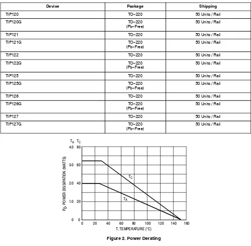
Total Power Dissipation @ TC = 25°C
Unclamped Inductive Load Energy (Note 1) E 50 mJ
Operating and Storage Junction, Temperature Range TJ, Tstg – 65 to + 150 °C
THERMAL CHARACTERISTICS
Characteristic Symbol Max Unit
Thermal Resistance, Junction−to−Case RqJC 1.92 °C/W
Thermal Resistance, Junction−to−Ambient RqJA 62.5 °C/W Stresses exceeding those listed in the Maximum Ratings table may damage the device. If any of these limits are exceeded, device functionality should not be assumed, damage may occur and reliability may be affected.
1. IC = 1 A, L = 100 mH, P.R.F. = 10 Hz, VCC = 20 V, RBE = 100 W
ÎÎÎÎÎÎÎÎÎÎÎÎÎÎÎÎÎÎÎÎÎÎÎÎÎÎÎÎÎÎÎÎÎ
ÎÎÎÎÎÎÎÎÎÎÎÎÎÎÎÎÎÎÎÎÎÎÎÎÎÎÎÎÎÎÎÎÎ
ELECTRICAL CHARACTERISTICS (TC = 25°C unless otherwise noted)
Characteristic Symbol Min Max Unit
OFF CHARACTERISTICS
Collector−Emitter Sustaining Voltage (Note 2)
(IC = 100 mAdc, IB = 0) TIP120, TIP125
Collector Cutoff Current
(VCE = 30 Vdc, IB = 0) TIP120, TIP125
Collector Cutoff Current
(VCB = 60 Vdc, IE = 0) TIP120, TIP125
ON CHARACTERISTICS (Note 2)
DC Current Gain (IC = 0.5 Adc, VCE = 3.0 Vdc)
Collector−Emitter Saturation Voltage (IC = 3.0 Adc, IB = 12 mAdc) TIP120, TIP121, TIP122
Cob −
−
300 200
pF
Product parametric performance is indicated in the Electrical Characteristics for the listed test conditions, unless otherwise noted. Product performance may not be indicated by the Electrical Characteristics if operated under different conditions.
TIP120, TIP121, TIP122 (NPN); TIP125, TIP126, TIP127 (PNP)
www.onsemi.com 3
Figure 1. Darlington Circuit Schematic BASE
EMITTER COLLECTOR
≈8.0 k ≈120
BASE
EMITTER COLLECTOR
≈8.0 k ≈120
ORDERING INFORMATION
Device Package Shipping
TIP120 TO−220 50 Units / Rail
TIP120G TO−220
(Pb−Free)
50 Units / Rail
TIP121 TO−220 50 Units / Rail
TIP121G TO−220
(Pb−Free)
50 Units / Rail
TIP122 TO−220 50 Units / Rail
TIP122G TO−220
(Pb−Free)
50 Units / Rail
TIP125 TO−220 50 Units / Rail
TIP125G TO−220
(Pb−Free)
50 Units / Rail
TIP126 TO−220 50 Units / Rail
TIP126G TO−220
(Pb−Free)
50 Units / Rail
TIP127 TO−220 50 Units / Rail
TIP127G TO−220
(Pb−Free)
50 Units / Rail
80
0
0 20 40 60 80 100 120 160
Figure 2. Power Derating T, TEMPERATURE (°C)
PD
, POWER DISSIP
A
TION (W
A
TTS)
40
20 60
140 TC
4.0
0 2.0
1.0 3.0 TA
TA
TIP120, TIP121, TIP122 (NPN); TIP125, TIP126, TIP127 (PNP)
www.onsemi.com 4
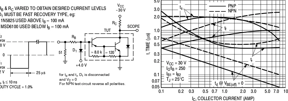
Figure 3. Switching Times Test Circuit
5.0
0.1
Figure 4. Switching Times IC, COLLECTOR CURRENT (AMP)
t, TIME
For NPN test circuit reverse all polarities. RB & RC VARIED TO OBTAIN DESIRED CURRENT LEVELS
D1 MUST BE FAST RECOVERY TYPE, eg:
Figure 5. Thermal Response t, TIME (ms)
TIP120, TIP121, TIP122 (NPN); TIP125, TIP126, TIP127 (PNP)
www.onsemi.com 5
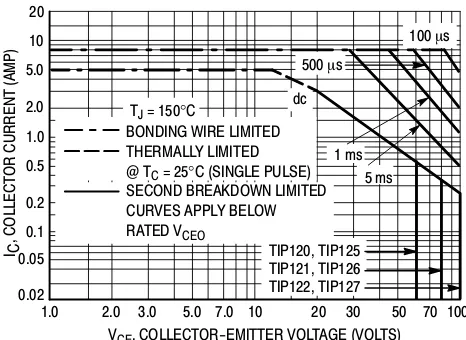
20
1.0
Figure 6. Active−Region Safe Operating Area VCE, COLLECTOR-EMITTER VOLTAGE (VOLTS)
10
BONDING WIRE LIMITED THERMALLY LIMITED
SECOND BREAKDOWN LIMITED CURVES APPLY BELOW RATED VCEO
5 ms
There are two limitations on the power handling ability of a transistor: average junction temperature and second breakdown. Safe operating area curves indicate IC− VCE
limits of the transistor that must be observed for reliable operation, i.e., the transistor must not be subjected to greater dissipation than the curves indicate.
The data of Figure 6 is based on TJ(pk) = 150°C; TC is
variable depending on conditions. Second breakdown pulse limits are valid for duty cycles to 10% provided TJ(pk)
< 150°C. TJ(pk) may be calculated from the data in Figure 5.
At high case temperatures, thermal limitations will reduce the power that can be handled to values less than the limitations imposed by second breakdown
300
0.1
VR, REVERSE VOLTAGE (VOLTS)
30
2.0 5.0 10 20 50 100 0.2 0.5 1.0
C, CAP
ACIT
ANCE (pF) 100
50
Figure 7. Small−Signal Current Gain 10,000
1.0
f, FREQUENCY (kHz) 10
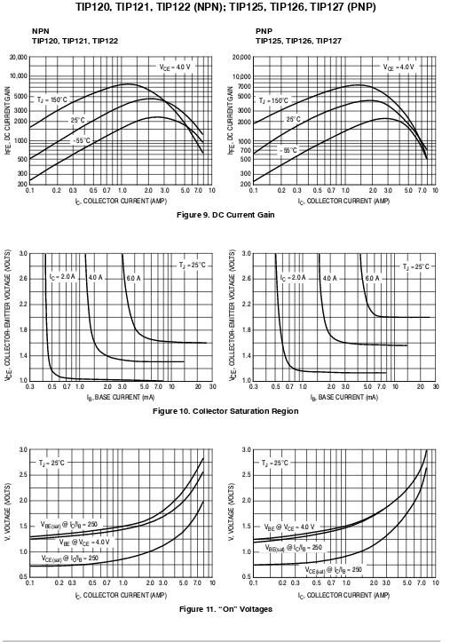
TIP120, TIP121, TIP122 (NPN); TIP125, TIP126, TIP127 (PNP)
Figure 9. DC Current Gain IC, COLLECTOR CURRENT (AMP)
200
, DC CURRENT
GAIN
TIP120, TIP121, TIP122
PNP
TIP125, TIP126, TIP127
Figure 10. Collector Saturation Region 3.0
IC, COLLECTOR CURRENT (AMP)
0.2 0.3 0.5 1.0 2.0 5.0 10
Figure 11. “On” Voltages VBE @ VCE = 4.0 V
IC, COLLECTOR CURRENT (AMP)
h FE
, DC CURRENT
GAIN
IC, COLLECTOR CURRENT (AMP)
TIP120, TIP121, TIP122 (NPN); TIP125, TIP126, TIP127 (PNP)
1. DIMENSIONING AND TOLERANCING PER ANSI Y14.5M, 1982.
2. CONTROLLING DIMENSION: INCH. 3. DIMENSION Z DEFINES A ZONE WHERE ALL
BODY AND LEAD IRREGULARITIES ARE ALLOWED.
DIM MIN MAX MIN MAX MILLIMETERS INCHES
A 0.570 0.620 14.48 15.75
B 0.380 0.415 9.66 10.53
C 0.160 0.190 4.07 4.83
D 0.025 0.038 0.64 0.96
F 0.142 0.161 3.61 4.09
G 0.095 0.105 2.42 2.66
H 0.110 0.161 2.80 4.10
J 0.014 0.024 0.36 0.61
K 0.500 0.562 12.70 14.27
L 0.045 0.060 1.15 1.52
N 0.190 0.210 4.83 5.33
Q 0.100 0.120 2.54 3.04
R 0.080 0.110 2.04 2.79
S 0.045 0.055 1.15 1.39
T 0.235 0.255 5.97 6.47
U 0.000 0.050 0.00 1.27
V 0.045 --- 1.15
---ON Semiconductor and the are registered trademarks of Semiconductor Components Industries, LLC (SCILLC) or its subsidiaries in the United States and/or other countries. SCILLC owns the rights to a number of patents, trademarks, copyrights, trade secrets, and other intellectual property. A listing of SCILLC’s product/patent coverage may be accessed at www.onsemi.com/site/pdf/Patent−Marking.pdf. SCILLC reserves the right to make changes without further notice to any products herein. SCILLC makes no warranty, representation or guarantee regarding the suitability of its products for any particular purpose, nor does SCILLC assume any liability arising out of the application or use of any product or circuit, and specifically disclaims any and all liability, including without limitation special, consequential or incidental damages. “Typical” parameters which may be provided in SCILLC data sheets and/or specifications can and do vary in different applications and actual performance may vary over time. All operating parameters, including “Typicals” must be validated for each customer application by customer’s technical experts. SCILLC does not convey any license under its patent rights nor the rights of others. SCILLC products are not designed, intended, or authorized for use as components in systems intended for surgical implant into the body, or other applications intended to support or sustain life, or for any other application in which the failure of the SCILLC product could create a situation where personal injury or death may occur. Should Buyer purchase or use SCILLC products for any such unintended or unauthorized application, Buyer shall indemnify and hold SCILLC and its officers, employees, subsidiaries, affiliates, and distributors harmless against all claims, costs, damages, and expenses, and reasonable attorney fees arising out of, directly or indirectly, any claim of personal injury or death associated with such unintended or unauthorized use, even if such claim alleges that SCILLC was negligent regarding the design or manufacture of the part. SCILLC is an Equal Opportunity/Affirmative Action Employer. This literature is subject to all applicable copyright laws and is not for resale in any manner.
PUBLICATION ORDERING INFORMATION
N. American Technical Support: 800−282−9855 Toll Free USA/Canada
Europe, Middle East and Africa Technical Support:
Phone: 421 33 790 2910
Japan Customer Focus Center
Phone: 81−3−5817−1050
TIP120/D
LITERATURE FULFILLMENT:
Literature Distribution Center for ON Semiconductor P.O. Box 5163, Denver, Colorado 80217 USA
Phone: 303−675−2175 or 800−344−3860 Toll Free USA/Canada
Fax: 303−675−2176 or 800−344−3867Toll Free USA/Canada
Email: [email protected]