Christian Gehrmann
Joakim Persson
Ben Smeets
British Library Cataloguing in Publication Data Gehrmann, Christian
Bluetooth security.—(Artech House computing library)
1. Bluetooth technology—Security measures 2. Computer security I. Title II. Persson, Joakim III. Smeets, Ben
005.8
ISBN 1-58053-504-6 Cover design by Igor Valdman
© 2004 ARTECH HOUSE, INC. 685 Canton Street
Norwood, MA 02062
All rights reserved. Printed and bound in the United States of America. No part of this book may be reproduced or utilized in any form or by any means, electronic or mechanical, including photocopying, recording, or by any information storage and retrieval system, without permission in writing from the publisher.
All terms mentioned in this book that are known to be trademarks or service marks have been appropriately capitalized. Artech House cannot attest to the accuracy of this information. Use of a term in this book should not be regarded as affecting the validity of any trademark or service mark.
Preface xi
Part I: Bluetooth Security Basics 1
1 Introduction 3
1.1 Bluetooth system basics 3
1.1.1 Background 3
1.1.2 Trade-offs 4
1.1.3 Bluetooth protocol stack 4
1.1.4 Physical layer 6
1.1.5 Baseband 7
1.1.6 Link manager protocol 13
1.1.7 Logical link control and adaptation protocol 15
1.1.8 Host control interface 15
1.1.9 Profiles 17
1.2 Bluetooth security basics 19
1.2.1 User scenarios 19
1.2.2 Notions and terminology 22
References 25
2 Overview of the Bluetooth Security Architecture 27
2.1 Key types 27
2.2 Pairing and user interaction 29
2.3 Authentication 30
2.4 Link privacy 31
2.4.1 Protect the link 32
2.4.2 Encryption algorithm 32
2.4.3 Mode of operation 34
2.4.4 Unicast and broadcast 36
2.5 Communication security policies 37
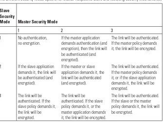
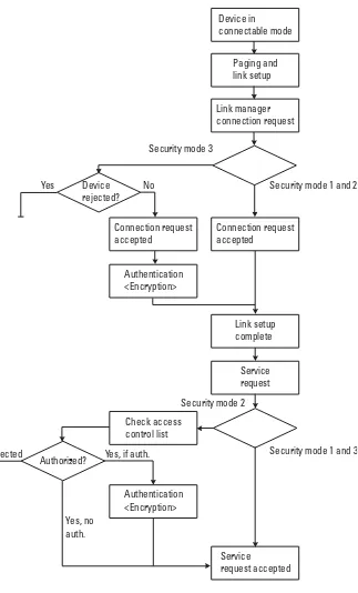
2.5.1 Security modes 38
2.5.2 Security policy management 42
References 42
3 Bluetooth Pairing and Key Management 43
3.1 Pairing in Bluetooth 43
3.2 HCI protocol 44
3.3 LM protocol 45
3.4 Baseband events 46
3.4.1 Initialization key generation 47
3.4.2 Unit key generation 47
3.4.3 Combination key generation 49
3.4.4 Authentication 50
3.4.5 Master key generation 52
3.5 User interaction 53
3.6 Cipher key generation 54
3.6.1 Encryption keyKC 54
3.6.2 Constraint keyKC′ 55
3.6.3 Payload keyKP 57
3.7 Key databases 58
3.7.1 Unit keys generation requirements 58
3.7.3 Key databases 60
3.7.4 Semipermanent keys for temporary use 63
References 63
4 Algorithms 65
4.1 Crypto algorithm selection 65
4.1.1 Block ciphers 65
4.1.2 Stream ciphers 66
4.2 SAFER+ 67
4.2.1 Authentication algorithmE
1 70
4.2.2 Unit key algorithmE
21 71
4.2.3 Initial key algorithmE
22 72
4.2.4 Encryption key algorithmE
3 73
4.3 Encryption engine 73
4.4 Ciphering algorithmE0 74
4.4.1 Initialization 77
4.5 Implementation aspects 79
References 80
5 Broadcast Encryption 81
5.1 Overview 81
5.2 Preparing for broadcast encryption 82
5.3 Switching to broadcast encryption 83
References 85
6 Security Policies and Access Control 87
6.1 Objectives 87
6.1.1 Trust relations 88
6.1.2 Security levels 88
6.1.3 Flexibility 89
6.1.4 Implementation considerations 89
6.2 Security manager architecture 90
6.2.2 Device trust level 91
6.2.3 Security level for services 92
6.2.4 Connection setup 92
6.2.5 Database contents and registration procedure 95
Reference 96
7 Attacks, Strengths, and Weaknesses 97
7.1 Eavesdropping 97
7.2 Impersonation 105
7.3 Pairing 107
7.4 Improper key storage 109
7.4.1 Disclosure of keys 110
7.4.2 Tampering with keys 111
7.4.3 Denial of service 111
7.5 Unit key 112
7.6 Location tracking 113
7.6.1 Bluetooth device address and location tracking 113 7.6.2 Five different types of location tracking attacks 115
7.7 Implementation flaws 116
References 117
Part II: Bluetooth Security Enhancements 121
8 Providing Anonymity 123
8.1 Overview of the anonymity mode 123
8.2 Address usage 124
8.2.1 The fixed device address,BD_ADDR_fixed 124
8.2.2 The active device address,BD_ADDR 125
8.2.3 Alias addresses,BD_ADDR_alias 128
8.3 Modes of operation 128
8.4 Inquiry and paging 129
8.4.1 Connectable mode 129
8.4.3 General connectable mode 131
8.5 Alias authentication 131
8.6 Pairing 133
8.7 Anonymity mode LMP commands 133
8.7.1 Address update,LMP active address 134
8.7.2 Alias address exchange,LMP alias address 134 8.7.3 Fixed address exchange, LMP fixed address 135
8.8 Pairing example 136
References 138
9 Key Management Extensions 139
9.1 Improved pairing 140
9.1.1 Requirements on an improved pairing protocol 140
9.1.2 Improved pairing protocol 141
9.1.3 Implementation aspects and complexity 147
9.2 Higher layer key exchange 149
9.2.1 IEEE 802.1x port-based network access control 150 9.2.2 Higher layer key exchange with EAP TLS 152
9.3 Autonomous trust delegation 154
9.3.1 Security group extension method 154
9.3.2 Public key–based key management 160
9.3.3 Group extension method versus public key method 163
References 164
10 Security for Bluetooth Applications 167
10.1 Headset 168
10.1.1 Headset security model 168
10.1.2 Pass-key and key management 169
10.1.3 Example 171
10.2 Network access 173
10.2.1 Common access keys 174
10.2.2 Security architecture 175
10.2.4 Initial connection 177
10.2.5 Subsequent access to NAcPs 179
10.3 SIM access 181
10.3.1 The SIM access profile 181
10.3.2 Securing SIM access 182
References 184
Glossary 187
List of Acronyms and Abbreviations 189
About the Authors 195
The simple wireless connectivity Bluetooth technology offers is attractive. Therefore, Bluetooth-equipped devices have found their way into quite different environments and are used for a wide range of applications. However, the secu-rity aspects must be carefully analyzed in order to decide whether Bluetooth technology indeed provides the right solution for a particular task.
Several books about Bluetooth wireless technology have been written. While these books are excellent at describing the general functionality of Blue-tooth devices, they are not particularly detailed when it comes to the security-related aspects of Bluetooth technology. This book is different in this respect, since it is completely devoted to security matters.
The security features that are defined in the specification are thoroughly discussed and described in the book. Moreover, several interesting facts with respect to this are pinpointed. Specifically, both strong and weak points of Blue-tooth security are identified. Additionally, we do not limit ourselves to what directly has been written in the specification. We also want to give some insight into how potential risks and security threats will affect deployment of Bluetooth technology.
This book is divided into two parts. Chapters 1 through 7 (Part I) discuss the security functionality defined on the basis of the Bluetooth version 1.2 speci-fication. However, security is not a feature that comes alone in a system. Secu-rity only has a meaning in a certain context. Therefore, the first chapter of this book provides an overview of the Bluetooth system. The communication princi-ples and the security-related functions in the system are covered. For the reader not familiar with security concepts and terminology, the notions and terms used in this book are explained. The security-related functions in the Bluetooth
specification are spread over several parts in the system. This explains why it is quite hard to grasp how the different security functions fit together from just reading the specifications. Chapter 2 gives an overview of the whole Bluetooth security architecture. This covers everything from the low-level functions like encryption and authentication to security policies. One core functionality in all security systems is key management. Secure generation, exchange, and distribu-tion of keys is maybe the most challenging task when designing a communica-tion security system. Chapter 3 describes Bluetooth key management. Bluetooth offers link encryption and secure device identification, which is provided by using two different core cryptographic algorithms in various ways. Chapter 4 gives a detailed description of the algorithms and the design principles behind them. Point-to-point encryption is different from sending encryption from one device to several receivers. The Bluetooth standard includes a broadcast encryp-tion funcencryp-tion. The broadcast funcencryp-tion is described in detail in Chapter 5. Often overlooked by communication system designers are security problems that are not directly related to the communication between devices but are related to the services offered by the devices. Even if strong encryption and identification are provided on a communicating link, the services that utilize the link must use the mechanism in a correct way. This is handled by introducing security policies, which in turn are enforced by access control mechanisms. Chapter 6 describes how this can be dealt with in a Bluetooth system. The last chapter of the first part of this book describes attacks on Bluetooth security. Obviously, it is impos-sible to correctly judge the appropriate usage of a security technology without a good understanding of the potential weaknesses. We cover all the main reported attacks on the system.
1
Introduction
Bluetooth wireless technology is gradually becoming a popular way to replace existing wireline connections with short-range wireless interconnectivity. It is also an enabling technology for new types of applications. In this chapter we give a short background and a condensed description of how the Bluetooth sys-tem works. We will focus on details that directly or indirectly relate to security issues and on the functionality that is important in order to understand the con-cept of the technology. The reference documentation for Bluetooth wireless technology is [1].
1.1 Bluetooth system basics
1.1.1 Background
Bluetooth wireless technology is a short-range radio technology that is designed to fulfill the particular needs of wireless interconnections between different per-sonal devices, which are very popular in today’s society. The development of Bluetooth started in the mid-1990s, when a project within Ericsson Mobile Communications required a way to connect a keyboard to a computer device without a cable. The wireless link turned out to be useful for many other things, and it was developed into a more generic tool for connecting devices. A synchro-nous mode for voice traffic was added and support for up to seven slaves was introduced. In order to gain momentum for the technology and to promote acceptance, the Bluetooth Special Interest Group (SIG) was founded in 1998. The group consists of many companies from various fields. By joining forces, the SIG members have evolved the radio link to what is now known as Blue-tooth wireless technology.
1.1.2 Trade-offs
Bluetooth wireless technology is targeting devices with particular needs and con-straints. The main issues are, as with all battery-powered consumer electronics, cost and power consumption. Consequently, certain design trade-offs have been made between the cost and power consumption on one side and overall per-formance on the other. For instance, some of the specified requirements for the radio (particularly the sensitivity numbers) are chosen to be so relaxed that it is possible to implement a rather cheap one-chip radio with very few external com-ponents (such as filters). The price paid is in a shortening of the range, as it will decrease with decreased sensitivity. On the other hand, some requirements are quite stringent (e.g., adjacent channel rejection) in order to handle interference at frequencies near the intended signal. This helps to keep up the aggregated throughput when many links are running simultaneously. One major design goal is to have the system quite robust in noisy environments. This is because interference rather than range is expected to be the limiting factor of the per-ceived performance.
In contrast to most other well-known radio standards used for data com-munication [e.g., Institute of Electrical and Electronics Engineers (IEEE) 802.11b and HIPERLAN], the specification has been written from the begin-ning with use cases for handheld personal devices in mind. In particular, there is no need to have an infrastructure (i.e., base stations) in place. The flexible Blue-tooth master-slave concept was introduced to fit well in a dynamically changing constellation of devices that communicate with each other. Furthermore, due to the wide range of requirements for the traffic types for different applications, Bluetooth can handle various data transport channels: asynchronous, isochro-nous, and synchronous. It is even possible for a device to mix asynchronous (data) and synchronous (voice) traffic at the same time.
In a radio environment where communication links are set up on request rather than by default (without the need for a centralized infrastructure, as in cellular networks) and where any node is able to communicate with any other node, networking is usually calledad hoc networkingorad hoc connectivity. As we will discuss later in the book, ad hoc connections impose special requirements for the security functionality for the system. Bluetooth wireless technology is particularly well suited for ad hoc usage scenarios.
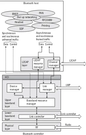
1.1.3 Bluetooth protocol stack
Above the physical layer is thebaseband layer, which is divided into lower and upper parts. In the following, we will not differentiate between these, but simply refer to them as the baseband. It is at this layer that packets are
Bluetooth host
BNEP PAN
Dial-up networking
Headset RFCOMM
SDP
Printing
Synchronous and isochronous unframed traffic
Asynchronous and isochronous framed traffic
Data Control Data Control
L2CAP layer
L2CAP resource manager
Channel manager
Device manager
Link manager
Baseband resource manager
Link controller
RF Upper
baseband layer
Lower baseband layer
Physical layer
Bluetooth controller HCI
L2CAP
LMP
Link controller
Radio
formatted: creation of headers, checksum calculations, retransmission proce-dure, and, optionally, encryption and decryption are handled. Thelink control-ler(LC) is the entity that implements the baseband protocol and procedures.
Bluetooth links are managed by thelink manager(LM). The devices set up links, negotiate features, and administer connections that are up and running using thelink manager protocol(LMP).
Large chunks of user data need to be reformatted into smaller units before they can be transmitted over the Bluetooth link. It is the responsibility of the logical link communication and adaptation protocol(L2CAP) to take care of this. At this layer it is possible to ask for certainquality-of-service(QoS) values one would like to reserve for the link.
In many cases, the Bluetooth functionality is to be integrated into a host entity that has computational power but lacks the radio part. For this purpose, Bluetooth moduleshandling only the lower layers exist. The entity handling the functionality of these layers is sometimes referred to as theBluetooth controller. For instance, a laptop that is perfectly capable of handling higher protocol layers can embed a module that handles radio, baseband, and L2CAP. In such a setup, the higher layers that are implemented in the host entity will communicate with the lower layers of the module through thehost controller interface(HCI).
1.1.4 Physical layer
Bluetooth radio operates in the license-free and globally availableindustrial, sci-entific, and medical(ISM) band at 2.4 GHz. Because the ISM band is free, Blue-tooth has to share this frequency band with many other systems. Various wireless communication systems operate in this band (besides Bluetooth, IEEE 802.11b, most notably). Other systems may be defined in the future. One other common device emitting radio frequency power in this band is found in almost all homes: the microwave oven. Even though the vast majority of the radiation is absorbed by the food inside the oven, some of it leaks and will appear outside as interference. Actually, the leakage may be as much as 1,000 times more power-ful than the signal one tries to capture, so this interference cannot be neglected. Fortunately, the interference is not there all the time (loosely speaking, the radiation cycle follows the frequency of the power supply) and is not over the entire frequency spectrum (approximately 15 to 20 MHz of the frequency band is affected by the microwave oven).
later, will hopefully be on a good channel. In general, faster hopping between frequencies gives more spreading, which improves on protection from other interference. However, the improved performance comes at the cost of increased complexity. The hopping rate chosen for Bluetooth is considered to be a good trade-off between performance and complexity.
The signal is transmitted using binary Gaussian frequency shift keying. The raw bit rate is 1 Mbps, but due to various kinds of protocol overhead, the user data rate cannot exceed 723 Kbps. Following regulatory bodies in different parts of the world, the maximum transmit power is restricted to 100 mW (or, equiva-lently, 20 dBm). It is expected that this will give a range of 100m at line of sight. Another power class, where the output power is restricted to 1 mW (0 dBm), is also defined. Radios of this power class are more common in handheld devices, and they will have a range of approximately 10m at line of sight.
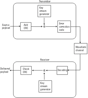
One should notice that the specification defines the sensitivity level for the radio such that the rawbit error rate(BER) 10−3is met, which translates into the range numbers given above within the specified link budget. It is around this raw BER that a voice link without error-correcting capabilities becomes noticea-bly distorted. This is a major reason for the choice of the BER 10−3as a bench-mark number for the radio specification. However, for data traffic, Bluetooth appliescyclic redundancy check(CRC) as well as optional error correction codes. Thus, if the receiver detects a transmission error, it will request a retransmission. The result is that when operating at BER 10−3(and even worse, to some extent), a data link will function quite well anyway. Depending on payload lengths and packet types, the decrease in throughput may even be unnoticed by the user. This is, of course, good for the users, but also for potential eavesdroppers, who may be able to choose a position at a safe distance beyond the specified range for their purposes.
1.1.5 Baseband
Addressing and setting up connections
The first step in finding other devices is to send an inquiry message. This message is repeatedly transmitted following a well-defined, rather short hop sequence of length 32. Any device that wants to be visible to others (also known as beingdiscoverable) frequently scans the inquiry hop sequence for inquiry mes-sages. This procedure is referred to as inquiry scan. A scanning device will respond to inquiries with its BD_ADDR and the current value of its native clock. The inquiry message is anonymous and there is no acknowledgment to the response, so the scanning device has no idea who made the inquiry, nor if the inquirer received the response correctly.
The inquirer gathers responses for a while and can, when so desired, reach a particular device through a page message. This message is sent on another length 32 hop sequence determined from the 24 least significant bits of the BD_ADDR[these are denoted bylower address part(LAP)] of the target device. A device listens for page messages when it is in the page scanstate. The phase (i.e., the particular position) of the FH sequence is determined from the device’s native clock. The paging device has knowledge of this from the inquiry response; thus it is possible for the paging device to hit the correct frequency of the paged device fairly quickly. As already has been stated, the inquiry part can be bypassed when two units have set up a connection before and want to con-nect again. If a long time has passed since the previous concon-nection, the clocks of the devices may have drifted, causing the estimate of the other unit’s native clock to be inaccurate. The only effect of this is that the connection set-up time may increase because of the resulting misalignment of their respective phase in the page hop sequence.
When a page response is received, a rough FH synchronization has been established between the pager and the paged device. By definition, the pager is themasterand the paged device is theslave. The meaning of these terms will be discussed in the next section. Before the channel can be set up, some more infor-mation must be exchanged between the devices. The FH sequence, the timing, and the channel access code (CAC) are all derived from the master device. In order to fine tune the FH synchronization, the slave needs theBD_ADDRand the native clock of the master. This information is conveyed in a special packet sent from the master to the slave. With all information at hand at the slave side, the master and slave can switch from the page hopping sequence (defined by the slave) to the basic channel hopping sequence determined by the master’s parameters. Details on this process can be found in [2].
Topology and medium access control
simplest form of piconet is illustrated in Figure 1.2(a). Information exchange within the piconet is done by sending packets back and forth between devices. Full duplex is accomplished using atime division duplexmode; that is, the chan-nel access is divided into time slots assigned to the communicating parties. Who gets access to the channel is determined by the piconet master simply by address-ing a slave, which will then have the right to send in the next time slot.
Being in connection state, the piconet devices follow a long deterministic FH sequence determined from the master’s LAP and native clock. The length of this sequence is 223, which roughly corresponds to a 23-hour cycle. Following from the fact that a device can only be master of one piconet at a time, every piconet will have different FH sequences. To stay tuned to its piconet, each slave member must continuously adjust for clock drift to the master by monitoring the traffic sent over the channel.
Only master-to-slave and slave-to-master communication is possible. Consequently, slave-to-slave traffic must be relayed via the master. If one par-ticular device is involved in all traffic, there is a risk that it becomes a bottleneck for the data transfer. This property is suboptimal with respect to the aggregated system throughput. However, an important concept in Bluetooth is that all devices have the ability to take the role of either slave or master, so the slaves may choose to create another piconet. Doing so is better for the aggregated throughput, since quite many piconets can actually be operated in parallel before mutual interference cancels the benefits inherent in the parallelism. This principle is shown in Figure 1.2(b).
In principle, a Bluetooth device is allowed to participate in more than one piconet simultaneously, as illustrated in Figure 1.2(c). This is accomplished using time sharing between the different piconets. To accommodate for this, the low-power modeshold, park, andsniffcan be used. Without going into detail,
M
M
M M M
S
S
S
S
S S
S
S
S S
S M
(a) (b) (c)
these modes make it possible for a device to temporarily leave a piconet to do something else (e.g., to sleep to save power or join another piconet). Thus, by having one device be a member of two piconets, it is possible to exchange infor-mation between piconets by relaying traffic via the common node. There are, of course, practical problems with this—such as timing issues and fulfilling quality of service when a device is absent from the piconet—but the possibility is given in the specification. One limitation is that a device can only be the master in at most one of the piconets of which it is a member.
Traffic types
Bluetooth wireless technology is designed to handle quite different types of traf-fic scenarios. Data may be sent without any QoS requirements (referred to as best effort traffic); thus, no bandwidth needs to be reserved and there are no requirements for latency or delay. Typically, file transfer and data synchroniza-tion fall into this category. Sometimes this traffic is called asynchronous. For real-time, two-way communication, the round-trip delay must be kept small, as do variations in the interarrival time of data samples. If not, the quality will be perceived as unacceptable. This type of traffic is referred to assynchronous. Typi-cal examples are speech and video conversations. Streaming audio and video falls somewhere in between these categories. Small time variations between data sam-ples is still important, but latency and roundtrip delays are of less interest. Such traffic is called isochronous. Bluetooth can handle all these traffic types—it is even possible to mix asynchronous and synchronous traffic between the master and a slave at the same time.
A synchronous link in Bluetooth is referred to as asynchronous connection-oriented(SCO) link. It is a point-to-point link between the master and a slave where traffic is sent on slots reserved at regular intervals. Another logical link that carries traffic on reserved slots is called enhanced synchronous connection-oriented (eSCO) link. Both these logical links provide constant rate data services by carry-ing fixed-sized packets on reserved slots over the physical channel. The eSCO link (introduced in Bluetooth version 1.2) is more flexible than the SCO link in that it offers more freedom in choosing bit rates and it is more reliable, as a lim-ited number of retransmissions can take place in between the reserved time slots.
The asynchronous connection-oriented (logical transport) (ACL) link is a point-to-multipoint link between the master and all the slaves on the piconet. No reserved slots are used. The master can address an arbitrary slave at any slot not reserved for SCO/eSCO traffic, even one that has a SCO/eSCO logical link running with the master.
Packet structure
synchronize the receiver. Each piconet uses a unique access code derived from theBD_ADDRof the master. Thus, by inspecting the access code, a receiver can determine if a packet is for another piconet. In that case, processing the rest of the packet can be aborted, which will help it save some power. Moreover, as the access code defines where a slot boundary is, it is used to time-synchronize the slave to the master clock. This is necessary, as time drift is inevitable between different devices due to differences in their respective crystal frequencies. Conse-quently, each slave of a piconet must continuously adjust its clock offset relative to the master clock; otherwise it will eventually lose connection with the master. The packet header is used to address individual slaves of a piconet. For this purpose, a 3-bit field denoted bylogical transport address(LT_ADDR) is used.1 The master assigns nonzero addresses to slaves at connection setup, while the all-zero address is reserved for broadcast messages. Apart from this, the packet header conveys information regarding the type of data traffic, flow control, and the retransmission scheme. To increase the robustness of the packet header, it is encoded with a rate R = 1/3 repetition code (i.e., each bit is repeated three times).
User data is carried by the payload. The length of this field can vary depending on the type of traffic—from zero bytes (for acknowledgment of received data when nothing needs to be sent in the reverse direction) up to 339 bytes (plus 4 bytes of payload header and CRC). The packet format is depicted in Figure 1.3.
A baseband packet may occupy up to 1, 3, or 5 slots, depending on its type. This allows for having asymmetric data rates in the forward and reverse
Access code Header Payload
Preamble Sync word Trailer
LT_ADDR Type
ARQN Flow SEQN
HEC
4 64 4
72 18 0 – 2,744
Figure 1.3 Packet format used in Bluetooth. The numbers refer to the number of bits before channel encoding.
directions without the overhead penalty that one-size packets would cause. Error detection may be applied through a 16-bit CRC code. Furthermore, it is possi-ble to apply an error correcting code to the payload—either a rateR=1/3 repe-tition code, or a (15,10) shortened Hamming code [3] (which has rate R = 2/3)—when link conditions are bad. In the Bluetooth specification, one uses the notionforward error correction(FEC) for this.
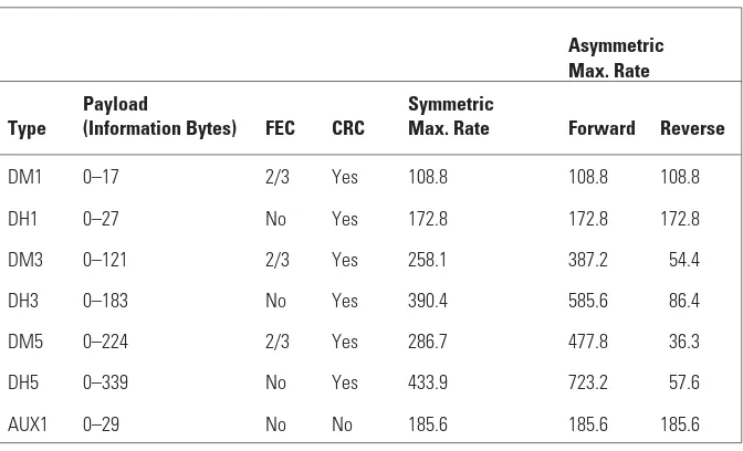
Best effort traffic (i.e., ACL links) without an error correcting code are car-ried over packets denoted by DH1, DH3, and DH5, where D indicates data, H stands for high rate, and the number is the maximum number of slots occupied by the packet. Similarly, there are DM1, DM3, and DM5 packets (where M stands for medium rate) for packets utilizing the shortened Hamming code. Using these packet types, it is possible to have user data rates ranging from 108.8 Kbps (sym-metric, DM1) to 723.2 Kbps (forward) and 57.6 Kbps (reverse) for DH5 packets. The achievable data rates using ACL packets are summarized in Table 1.1.
For synchronous traffic, there are the HV1, HV2, and HV3 [where H stands for high-quality (referring to the relatively high bit rate available for speech coding) and V stands for voice] packets of 10, 20, and 30 information bytes, respectively. These one-slot packets have no CRC applied to the payload and are typically used to carry voice traffic. The achievable rate for all HV pack-ets is 64 Kbps. The HV1 packet is protected by the rateR=1/3 repetition code, the HV2 packet is protected by the rateR=2/3 Hamming code, and the HV3 packet has no error correcting code applied. There is also a DV packet which consists of two parts—one carrying 10 bytes of voice data (no CRC) and one
Table 1.1
Summary of ACL Packets and Their Achievable Data Rates (in Kbps)
Asymmetric Max. Rate
Type
Payload
(Information Bytes) FEC CRC
Symmetric
Max. Rate Forward Reverse
DM1 0–17 2/3 Yes 108.8 108.8 108.8
DH1 0–27 No Yes 172.8 172.8 172.8
DM3 0–121 2/3 Yes 258.1 387.2 54.4
DH3 0–183 No Yes 390.4 585.6 86.4
DM5 0–224 2/3 Yes 286.7 477.8 36.3
DH5 0–339 No Yes 433.9 723.2 57.6
carrying asynchronous user data (0 to 9 bytes) for which CRC is applied. The voice part also offers 64 Kbps. In addition to these, the eSCO logical transport is mapped on EV3, EV4, and EV5 packets. All these have a CRC, which implies that retransmission is possible if no acknowledgment has been received within the retransmission window. The EV4 also applies the error correcting code to the payload. For these packets, the achievable rates are 96, 192, and 288 Kbps, respectively. The rates that are supported for synchronous traffic are summa-rized in Table 1.2.
1.1.6 Link manager protocol
It is the link manager that is responsible for the control of the Bluetooth link. That includes all tasks related to the setup, detachment, or configuration of a link. The LM is also responsible for exchanging security-related messages. The LMs in different units exchange control messages using the LMP. A large set of control messages or LMPprotocol data units(PDU) have been defined. Many of these are security related and some PDUs are used to carry the information needed at pairing and authentication, and for enabling of encryption.
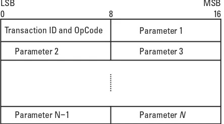
The LMP PDUs are transferred in the payload instead of ordinary data. They are always sent as single-slot packets and they can be carried in two differ-ent types of data packets. In order to distinguish LMP packets from other pack-ets, a special type code is used in the packet header of all LMP messages. To avoid overflow in the receiving packet buffer, flow control is normally applied to the asynchronous data packet in Bluetooth. However, no flow control applies to LMP PDUs. The LMP PDU payload format is shown in Figure 1.4. The
Table 1.2
Summary of Synchronous Packets and Their Achievable Data Rates (in Kbps)
Type
Payload
(Information Bytes) FEC CRC
Symmetric Max. Rate
HV1 10 1/3 No 64
HV2 20 2/3 No 64
HV3 30 No No 64
DV 10+(0–9)* 2/3* Yes* 64+57.6*
EV3 1–30 No Yes 96
EV4 1–120 2/3 Yes 192
EV5 1–180 No Yes 288
PDU format can be considered as one byte header followed by the LM data. The header has two fields. The first field is only 1 bit long and contains the transaction identifier (ID). The second field is 7 bits long and contains the
operation code(OpCode). The operation code tells which type of LMP PDU
that is being sent. Each LMP message has its unique OpCode.
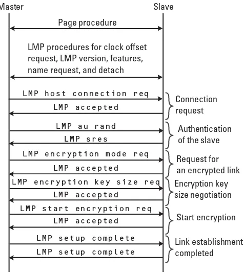
As we have described, the LMP is used to control and set up the link. A typi-cal PDU flow example at connection creation is shown in Figure 1.5. The con-nection establishment always starts with the master unit paging the slave unit. After the basic baseband page and page response messages have been exchanged, the setup of the link can start. Before the master sends a connection request, it might request information from the slave regarding its clock, version of the link manager protocol, LMP features, and the name of the slave units. A set of LMP PDUs has been defined for this purpose. The connection setup procedure then really starts with the master sending theLMP connection request mes-sage. Next, the security-related message exchange takes place. Finally, the peers complete the connection setup by exchangingLMP setup complete mes-sages. Special security related PDUs have been defined in order to accomplish:
• Pairing; • Authentication; • Encryption;
• Changing the link key.
The details of principles and usage are described in Chapters 2 and 3. In addition to the different LM functions we have mentioned previously, the LM is also responsible for performing role change (master-slave switch), controlling multislot packet size, and power control.
LSB 0
MSB 16
Parameter N 1−
Parameter 2 Parameter 3 Parameter 1 Transaction ID and OpCode
ParameterN 8
1.1.7 Logical link control and adaptation protocol
The L2CAP takes care of datagram segmentation and reassembly, multiplexing of service streams, and quality-of-service issues. The L2CAP constitutes a filter between the Bluetooth independent higher layers running on the host and the lower layers belonging to the Bluetooth module. For instance,transmission con-trol protocol/internet protocol(TCP/IP) traffic packets are too large to fit within a baseband packet. Therefore, such packets will be cut into smaller chunks of data before they are sent to the baseband for further processing. On the receiving side, the process is reversed; baseband packets are reassembled into larger entities before being released to higher layers.
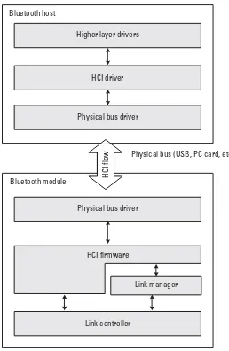
1.1.8 Host control interface
The HCI is a common standardized interface between the upper and lower lay-ers in the Bluetooth communication stack. As we described in Section 1.1.3, the HCI provides the capability of separating the radio hardware-related functions from higher layer protocols, which might run on a separate host processor. By using the HCI, it is possible to use one Bluetooth module for several different
Master Slave
Page procedure
LMP procedures for clock offset request, LMP version, features, name request, and detach
LMP host connection req LMP accepted
LMP setup complete LMP setup complete
LMP accepted LMP start encryption req
LMP accepted
LMP encryption key size req LMP accepted
Connection request
Authentication of the slave
Request for an encrypted link Encryption key size negotiation
Start encryption
Link establishment completed
LMP au rand LMP sres
LMP encryption mode req
hosts and applications. Similar, upper-layer applications implemented in one host can use any Bluetooth module supporting the HCI.
Figure 1.6 provides an overview of the lower Bluetooth layers and the HCI interface. The HCI commands for the Bluetooth module are handled by the HCI firmware that access the baseband and link manager.
Not all Bluetooth implementations run the lower and higher layer process-ing on different processors. Integrated implementations are also possible. Con-sequently, the HCI is an optional feature and only products that benefit from the separation use it.
Link controller
Link manager HCI firmware
Physical bus driver Bluetooth module
Physical bus (USB, PC card, etc.) Physical bus driver
HCI driver Higher layer drivers Bluetooth host
HCI
flow
The HCI commands are transported between the Bluetooth module and host by some physical bus. This can, for example, be auniversal serial bus(USB) or PC card connection. Three physical transport media have been defined [4]: USB, RS232, and universal asynchronous receiver/transmitter (UART). The host exchanges data with the module by usingcommand packets,and the module gives responses to these requests or sends its own commands to the host, which are calledevent packets. Data to be passed over a Bluetooth link is transported in data packets.
To prevent buffer overflow in the host controller, flow control is used in the direction from the host to the host controller. The host keeps track of the size of the buffer all the time. At initialization, the host issues the Read Buffer Sizecommand. The host controller then continuously informs the host of the number of completed transmitted packets through theNumber of Completed Packetevent.
The command packets can be divided into six different subgroups:
1. Link control commands; 2. Link policy commands;
3. Host controller and baseband commands; 4. Read information commands;
5. Read status commands; 6. Test commands.
The link control commands are used to control the link layer connections to other Bluetooth devices. Control of authentication and encryption as well as keys and pass-key commands belong to this subgroup. The policy commands are used to control how the link manager manages the piconet. The host con-troller and baseband commands are used to read and write into several different host controller registers. This includes reading and writing keys and pass-keys to or from the host controller, as well as reading and writing the general link man-ager authentication and encryption policy (see Section 2.5). The read informa-tion commands are used to get informainforma-tion about the Bluetooth device and the capabilities of the host controller. Information on connection states and signal strength can be obtained through the read status commands. Finally, the test commands are used to test various functionalities of the Bluetooth hardware.
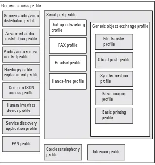
1.1.9 Profiles
defines an unambiguous description of the communication interface between two units for one particular service. Both basic profiles that define fundamental procedures for Bluetooth connections and profiles for distinct services have been defined.
A new profile can be built on existing ones, allowing efficient reuse of existing protocols and procedures. This gives raise to a hierarchical profiles structure as outlined in Figure 1.7. The most fundamental definitions, recom-mendations, and requirements related to modes of operation and connection and channel setup are given in thegeneric access profile(GAP). All other existing Bluetooth profiles make use of the GAP. The very original purpose of the Blue-tooth standard was short-range cable replacement. Pure cable replacement through RS232 emulation is offered by theserial port profile. Several other pro-files, like thepersonal area network(PAN) andlocal positioning profilemake use
Hands-free profile Headset profile
FAX profile Dial-up networking
profile Generic object exchange profile
Basic printing profile Basic imaging profile Synchronization profile
Object push profile File transfer profile
Service discovery application profile Human interface device profile
Common ISDN access profile Hardcopy cable replacement profile
Advanced audio distribution profile Generic audio/video distribution profile
PAN profile
Cordless telephony
profile Intercom profile Audio/video remove
control profile Generic access profile
Serial port profile
of theserial port profile. One level deeper in the profiles hierarchy is thegeneral object exchange profile. The purpose of this profile is to describe how the IrDA
object exchange(OBEX) layer is used within Bluetooth. OBEX can be used to
any higher layer object exchange, such as synchronization, file transfer, and push services.
Different services have different security requirements. In Section 10 we discuss the security requirements and solutions for a selection of Bluetooth pro-files. Most profiles benefit from using the baseband security functions. It is important, though, that the mechanisms are correctly understood and that application providers are aware of the strength as well as limitations of the link level security services. New profiles are constantly being developed, and some existing profiles may become replaced as others covering the same or similar functionality are added. Profiles are released independently of the core specifica-tion release schedule. In Figure 1.7 we have included the profiles that were adopted at the time of this writing (November 2003).
1.2 Bluetooth security basics
Security issues surfaced from the beginning in the design of the Bluetooth tem. It was decided that even for the simplest usage scenarios, the Bluetooth sys-tem should provide security features. To find the correct level of security when a new communication technology is defined is a nontrivial task, as it depends on usage. Bluetooth is versatile, which further increases the difficulties in finding the correct level one anticipates for the system. We start this section by discuss-ing some typical user scenarios for Bluetooth applications.
1.2.1 User scenarios
In Section 1.1.9 we touched upon Bluetooth profiles. The overview of the pro-files shows that the technology can be used in a large number of different appli-cations. The overview also demonstrates that very different devices with very different capabilities might utilize the local connectivity provided by Bluetooth. However, most applications are characterized by two things:personal area usage andad hoc connectivity. The Bluetooth link level security mechanisms have been designed with these two characteristics in mind, and below we describe what we mean by personal area networks and ad hoc connectivity.
Personal area networks
units can be under one user’s control (i.e., personal computing units) or they can be controlled by different users or organizations. Bluetooth is used as a local connection interface between different personal units, such as mobile phones, laptops,personal digital assistants(PDA), printers, keyboards, mouses, headsets, and loudspeakers. Hence, Bluetooth is a true enabling technology for the PAN vision. The devices are typically (but not at all limited to) consumer devices. Different consumer devices have different manufacturers, and the personal usage of a device will vary from person to person. Hence, in order to provide interoperability between the different personal devices, the security must to some extent be configured by the user. Bluetooth security solutions have been designed with the principles in mind that any ordinary user should be able to configure and manage the necessary security actions needed to protect the com-munication links.
The information exchanged over Bluetooth might very well be sensitive and vulnerable to eavesdropping. In addition, users of mobile phones or laptops would like to be sure that no unauthorized (by the users) person is able to con-nect to their personal devices. Another issue is location privacy. People would like to use their Bluetooth devices anywhere they go without fearing that some-body can track their movements. To ensure that, device anonymity is an impor-tant user expectation.
To sum up, there are four fundamental security expectations for Bluetooth:
1. Easy-to-use and self-explanatory security configuration; 2. Confidentiality protection;
3. Authentication of connecting devices; 4. Anonymity.
Bluetooth provides link encryption and authentication. In this book we will provide a possible solution for providing anonymity (see Chapter 8). If the expectation for easy-to-use and self-explanatory security configuration has also been fulfilled is hard to say—at least the system has been designed with this goal in mind.
Ad hoc connectivity
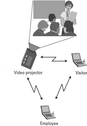
where two persons, an employee and a visitor, meet in a room equipped with a video projector, illustrated in Figure 1.8.
The two persons in the room are each carrying one laptop. The laptops contain presentation information that the users would like to present to each other using the video projector. Furthermore, after the presentation, the visitor would like to send a presentation to the employee. We assume that the video projector and the laptops support Bluetooth for local connectivity. Hence, we have a PAN scenario with three different Bluetooth-enabled devices:
1. A video projector; 2. A visitor laptop; 3. An employee laptop.
The ad hoc nature of these connections stems from the fact that no prior relation can be assumed between the visitor’s laptop and the projector or between the visitor and employee laptop. Hence, in order to provide security (authentication and encryption) on the communication links, the security rela-tions must be set up on the fly and often by the users themselves. The original Bluetooth pairing mechanism provides the possibility of setting up ad hoc secu-rity relations. However, one would like to minimize the load on the user and
Video projector Visitor
Employee
find alternative methods to manual procedures. In this book we revisit these issues several times and discuss features needed to make ad hoc connectivity as secure and, at the same time, as user friendly as possible. In the next chapter we will give an overview of the Bluetooth security architecture. But first we review some frequently used notions and terminology.
1.2.2 Notions and terminology
We already mentioned that security expectations for Bluetooth are related to the following four aspects (1) easy-to-use and self-explanatory security configura-tion, (2) confidentiality protecconfigura-tion, (3) authentication of connecting devices, and (4) anonymity. These aspects describe what we mean by security in this book. When considering general information systems, security is understood to encompass the following three aspects [5]: confidentiality, integrity, and avail-ability. The mechanisms that address the confidentiality aspects should provide the means to keep user information private. Integrity mechanisms address the capability to protect the data against unauthorized alterations or removal. Finally, availability deals with the aspect that the system should be available as expected. Availability is therefore closely related to reliability and robustness. Comparing this with what we said within the context of Bluetooth, we see that the aspects of confidentiality and availability appear in the four security expecta-tions, although it may be argued that anonymity is an aspect on its own. The Bluetooth standard does not currently include any data integrity protection mechanism. In the sections that follow, we discuss first the meaning of confi-dentiality and integrity in more detail. We then continue to give a very compact description of cryptographic mechanisms that are used to achieve security.
Confidentiality
is in the same order as the number of key combinations. In other words, break-ing the cipher is equivalent to a complete search through the key space.
Integrity
The second aspect of security, that is, integrity, is about ensuring that data has not been replaced or modified without authorization during transport or stor-age. Integrity should not be confused with peer authentication or identification (see the explanation below), which can be used to verify the communication peer during connection setup. Peer authentication only guarantees that a con-nection is established with the supposed peer, while message integrity is about authenticity of the transmitted messages. Integrity protection of transmitted data is not part of the Bluetooth standard.
Symmetric and asymmetric mechanisms
Cryptographic mechanisms are distinguished as being either symmetric key or
asymmetric key. Symmetric mechanisms are mechanisms for which the
commu-nicating parties share the same secret key. There is, so to speak, a symmetric situation among the parties. If the mechanism concerns the encryption of files, say, then the receiver is not only able to decrypt the files received from the trans-mitter, but in fact the receiver is able to decrypt encrypted files that were gener-ated by the receiver itself. Thus, a receiver cannot claim that the decrypted data indeed was sent by the sender. Symmetric mechanisms (we sometimes also use the wordschemes) are also calledsecret-key mechanisms. An important property of symmetric mechanisms is that the transportation of the key from the sending to the receiving party needs to be realized in such a way that no information about the key is leaked to outsiders. This need for key transfer constitutes the core problem in key management. Encryption of large data blocks is often realized through symmetric encryption mechanisms because they are faster than the asymmetric mechanisms. Secret-key mechanisms have a long history, and many variants are known and in use. The main two types of secret-key mechanisms are block and stream ciphers.
Asymmetric mechanisms are mechanisms that realize an encryption and decryption transformation pair for which the keys for the respective transforma-tions are not the same. In fact, one demands that one of the keys cannot be recovered from the other. Hence, the keys at the sending and receiving sides have an asymmetry in their properties. Asymmetric mechanisms are also called
public-key mechanisms. This naming stems from the fact that for asymmetric
have proofs of the binding between a public key and an entity who claims to be the owner (of the private key). A widespread solution to this is the use of so-called certificates. Such certificates bind a public key to an identity2 and are issued by a common trusted agent.
Public-key schemes are asymmetric cryptographic mechanisms. The two keys that relate to a pair of encryption and decryption transformations are called the public key and private key, respectively. Together they form a public- and private-key pair. In public-key schemes, the private key cannot be recovered by practical means from the public key or any other publicly known information for that matter.
The best known public-key schemes are the Rivest, Shamir, and Adleman (RSA) and Diffie-Hellman schemes. Both date back to the beginning of public-key cryptography in the 1970s. Diffie-Hellman is used for public-key establishment, while RSA is for key transport, encryption, or digital signatures. For more infor-mation and a historical overview, see [6].
Block and stream ciphers
Block ciphersare symmetric cryptographic mechanisms that transform a fixed
amount of plaintext data (a block) to a block of ciphertext data using a key, and that have an inverse transformation using the same key (as used for the encryp-tion transformaencryp-tion). See Figure 1.9(a). Block ciphers are very useful as building blocks to obtain other cryptographic mechanisms, such as authentication mechanisms. In Bluetooth, the SAFER+block cipher is used in this manner, as will be described in Section 4.2.
Stream ciphersare the other main type of symmetric cryptographic mecha-nisms. Here a stream (sequence) of plaintext symbols is transformed symbol by symbol in a sequence of ciphertext symbols by adding, symbol by symbol, a so-calledkey streamto the sequence of plaintext symbols. See Figure 1.9(b). Stream ciphers have a trivial inverse transformation. Just generate the same key stream and subtract its symbols from the stream of cipher symbols. Bluetooth uses the E0stream cipher to encrypt the data sent via the radio links.
Authentication
Authentication is the procedure by which a unit (the verifier) can convince itself about the (correct) identity of another unit (the claimant) it is communicating with3. Note that in cryptography, one often refers to this as the identification, and authentication is reserved for referring to (message or data) authenticity,
2. This is the most common use of certificates. However, there are types of certificates other than identity certificates, and certificates often carry other information as well, often telling about limitations of the use of the key (pair).
that is, the problem of asserting that a received message is authentic (as sent by the sender). Here we use the definition of authentication that is in use in many (cellular) communication systems [e.g., Global Mobile System (GSM) and wideband code division multiple access (WCDMA)], that is, it refers to the process of verifying the consistency of the link keys in the involved Bluetooth devices exchanged during the pairing procedure.
Authorization
Authorization is the process of giving someone permission to do or have access to something. For Bluetooth this means to decide whether a remote device has the right to access a service on the local host and what privileges to gain for it. Usually this involves some form of user interaction. Alternatively, granting access to services can be subject to device-specific settings. Sometimes authoriza-tion refers both to administering system permission settings and the actual checking of the permission values when a device is getting access.
References
[1] Bluetooth Special Interest Group,Specification of the Bluetooth System, Version 1.2, Core
System Package, November 2003.
[2] Bluetooth Special Interest Group,Specification of the Bluetooth System, Version 1.2, Core
System Package, Part B, Baseband Specification, Link Controller Operation, November 2003.
[3] Lin, S., and D. J. Costello Jr.,Error Control Coding: Fundamentals and Applications, Engle-wood Cliffs, NJ: Prentice-Hall, Inc., 1983.
[4] Bluetooth Special Interest Group,Specification of the Bluetooth System, Version 1.2, Core
System Package, Part E, Host Controller Interface Functional Specification, November 2003.
Plaintext block
Encrypt Key steamgenerator
Cipertext block
Key Key
Ciphertext symbol Ciphertext symbol Plaintext symbol
Plaintext symbol
+
+ −
(a) (b)
[5] CCITT: International Telegraph and Telephone Consultative Committee,X.800: Data Communication Networks: Open Systems Interconnection (OSI); Security, Structure and
Applications, International Telecommunication Union, Geneva, 1991.
2
Overview of the Bluetooth Security
Architecture
The security demands in the various usage scenarios for Bluetooth differ sub-stantially. For example, a remote-controlled toy and a remote-controlled indus-trial robot constitute usage cases with essentially different demands on security. The security architecture for Bluetooth is designed to provide built-in security features even for the simplest cases and at the same time provide adequate sup-port to provide security in demanding cases, such as those where Bluetooth devices are used in a network environment.
This chapter gives an overview of the Bluetooth security architecture, starting with a description of the different key types that are used, how the link encryption is organized, and how all the basic features are controlled through security modes to achieve different trust relations.
2.1 Key types
The security provided by the Bluetooth core is built upon the use of symmetric-key cryptographic mechanisms for authentication, link encryption, and symmetric-key gen-eration. A number of different key types are used in connection with these mechanisms. In Bluetooth, a link is a communication channel that is established between two Bluetooth devices. To check that a link is established between the correct devices, an authentication procedure between two devices has been introduced. The authentication mechanism in this procedure uses the so-called link key. As we will find out later, there are several different types of link keys. Link keys are not only used for authentication. They are also used for derivation
of the key that controls the encryption of the data sent via a link. Through this encryption, confidentiality of the transmitted data is realized. The correspond-ing encryption mechanism uses thelink encryption key. Loosely speaking, a link key is used for the authentication between two devices and to derive the link encryption key. A link key is created during the pairing of two devices. Section 2.2 contains more details on the pairing and use of pass-keys.
Before we discuss the pairing mechanism, it is useful to clarify the condi-tions under which communication between two devices will occur. It is impor-tant to distinguish two imporimpor-tant states. Firstly, we have the state in which a device wants to establish a connection with a device it has not been paired with. Secondly, we have the state where a device wants to communicate with a device it has paired with. Of course, a device may, as a result of a malfunction or a forced reset, have lost the pairing information associated with a device. In such a situation, the device should fall back to the unpaired state.
The pairing operation will result in a link key that two devices will use for authentication and link encryption key generation directly after the pairing and at later instances. The Bluetooth system recognizes two types of link keys:
semipermanent and temporary keys. Furthermore, two types of semipermanent
(link) keys are distinguished:unit keysandcombination keys. A unit key is a link key that one unit generates by itself and uses as a link key with any other (Blue-tooth) device, and a combination key is a key that a device generates in coopera-tion (combinacoopera-tion) with another device. Therefore, any unit key that a specific device has may be known to many other devices, whereas each combination key is only known to itself and the device with which it was generated. Unit keys can only be safely used when there is full trust among the devices that are paired with the same unit key. This is because every paired device can impersonate any other device holding the same unit key. Since Bluetooth version 1.2, the use of unit keys is not recommended. But, for legacy reasons, unit keys have not been completely removed from the specification. Besides the combination and unit keys, two other key types are used:initialization keysandmaster keys. These are temporary keys. The initialization key is a short-lived key that exists during the pairing of two devices. The master key is a link key that the master generates prior to the setup of an encrypted broadcast communication to several slave devices. Besides the link keys, we have three ciphering keys: the encryption key KC, theconstrained encryption keyKC′, and thepayload key KP. The encryption
key is the main key that controls the ciphering. Since this key may have a length (in bits) that exceeds legislative constraints on the maximally allowed key length, KC is not used directly but is replaced by the constrained encryption keyKC′,
ciphering key derived from the constrained encryption keyKC′. This key is the
initial state of the ciphering engine prior to generating the overlay sequence. A summary of the different key types can be found in Table 2.1. More details on the encryption keys is given in Section 2.4.1.
2.2 Pairing and user interaction
As indicated earlier, the pairing of two devices is the procedure by which two devices establish a shared secret that they can use when they meet again. The pairing requires user interaction, for example, the entering of a pass-key.1 See Figure 2.1(a). The Bluetooth system allows the pass-key to be 128 bits long. Such a large pass-key value would be rather user unfriendly for manual input. How-ever, this feature allows the use of a higher level automated key agreement scheme that can “feed” the agreed pass-key into the pairing procedure. See Figure 2.1(b). The high-level key agreement scheme can be a network ortransport layer security (TLS) protocol. Examples of such protocols are the Internet Engineering Task Force (IETF) protocols TLS [1] and Internet key exchange (IKE) [2].
There are two kinds of pass-keys in Bluetooth terminology: the variable pass-key and thefixedpass-key. The first type represents a pass-key that can be arbitrarily chosen at the pairing instance. This requires that some form of user interaction takes place in order to feed the Bluetooth device with the appropri-ate pass-key value. This interaction is most likely accomplished using a keyboard or numerical keypad. An example of a typical device with a variable pass-key is the mobile phone. In contrast, the fixed pass-key cannot be chosen arbitrarily when it is needed. Instead, a predetermined value must be used. This type of pass-key is used when there is no user interface to input a value to the Bluetooth
Table 2.1
Overview of Key Types
Purpose Semipermanent Temporary
Authentication key generation
Unit key Combination key Initialization key Master key
Ciphering Encryption key Constrained encryption key
Payload key
device. Clearly, for a pairing to work, only one device can have a fixed pass-key (unless, of course, both devices happen to have the same fixed pass-key). Exam-ples of devices in need of fixed pass-keys are Bluetooth-enabled mice and head-sets. These gadgets come with a factory preset pass-key when delivered to the customer.
Note that a fixed pass-key need not be “fixed” in the sense that it can never be changed. Preferably, the user is allowed to change the fixed pass- key in some way. In some scenarios, a wired connection could be used, for example, by plug-ging in an external keyboard and chanplug-ging the pass-key. This is only feasible if it is difficult for anyone but the rightful owner to have physical access to the Blue-tooth device in question. More interesting is to allow the change over BlueBlue-tooth using an already paired device (equipped with the necessary user interface) over asecure connection. This implies that the user connects to the device with a fixed pass-key, authenticates itself, and requests the link to be encrypted before a fresh pass-key value can be sent to the remote device. The new value replaces the old one and becomes the fixed pass-key to use in subsequent pairings. In Chapter 3 we will come back to the details of the pairing procedure.
2.3 Authentication
A Bluetooth device in a connectable state accepts connection requests from other devices. This means that there is a risk that a connectable device is con-nected to and attacked by a malicious device. Obvious, this can be avoided by never entering a connectable state. On the other hand, that implies that no Bluetooth connections at all can be established. Accordingly, there is a need to
Pass-key Pass-key
(a)
(b)
Device 1 Device 1
Device 2 Device 2
Key agreement
Key agreement
Pass-key Pass-key
securely identify the other communication peer so that connections from unknown devices can be refused. Device identification is provided through the Bluetooth authentication mechanism. The authentication procedure is a so-called challenge-response scheme, where theverifierdevice sends a random chal-lenge to the claimantdevice and expects a valid response value in return. The authentication procedure is only one way, and if mutual authentication is needed the procedure must be repeated with the verifier and claimant roles switched. In Section 3.4.4 the authentication procedure is described in more detail.
2.4 Link privacy
Of all security aspects encountered in wireless scenarios, the easiest to under-stand is the one relating to confidentiality. Eavesdropping on a radio transmis-sion can be accomplished without revealing anything to the victim. Radio waves are omnidirectional and travel through walls (at least to some extent). One can easily imagine hiding a small radio receiver close enough to intercept the mes-sages sent by a user, without revealing its presence to anyone not knowing where to look for it. It may even be possible to do this without having physical access to the premises where the Bluetooth devices are used. If the walls surrounding the user area are not completely shielding the radio transmissions, eavesdrop-ping can take place outside this room.
Initially, Bluetooth was envisioned as a simple cable replacement technol-ogy. For some applications (such as device synchronization), replacing the wire with a radio has implications for confidentiality. It was desirable that the user should not experience any decrease in confidentiality when comparing the wire-less with the wired solution. Thus, it was determined to look into what kind of security means were needed in order to give a sufficient degree of protection to Bluetooth communication.
2.4.1 Protect the link
It is important to understand that Bluetooth specifies security for the link between radio units, not for the entire path from source to destination at the application layer. All protocols and profiles that need end-to-end protection will have to provide for this themselves. The implications are obvious in access point scenarios, where the remote application may be running on a unit located thou-sands of kilometers away, and traffic routing will involve many unknown links apart from the short radio link between the local unit and the access point. Since the user has no control over this, higher layer security is an understandable pre-requisite to ensuring confidentiality all the way. However, even in the case when the source and destination reside on PDAs close to each other and there is only one direct Bluetooth link in between, one should remember that Bluetooth security only addresses the radio link. Who is really in control on the other side? Can malicious software access and control the Bluetooth radio?
2.4.2 Encryption algorithm
When it comes to the selection of which encryption algorithm to use, there are some considerations that need to be taken into account:
• Algorithmic complexity; • Implementation complexity; • Strength of the cipher.
Algorithmic complexity relates to the number of computations needed for encryption and decryption, while implementation complexity relates to the size of the implementation on silicon. These two items boil down to power con-sumption and cost—crucial properties for the battery-powered units Bluetooth is designed for. A complex algorithm will almost certainly require a larger foot-print on silicon than does a simple algorithm, leading to higher cost. For the implementation, sometimes the speed obtained from dedicated hardware can be traded for flexibility and smaller size using a programmable component such as a digital signal processor (DSP) or a small central processing unit(CPU). For such solutions, an increased algorithmic complexity will inevitably demand higher clocking frequency, which also increases power consumption.
strength of the cipher. In fact, the goal is to keep the algorithmic complexity low while having the computational complexity for all types of attacks as high as possible.
Bluetooth deploys a stream cipher (see Section 1.2.2) with the desired properties of a small and simple hardware solution while being difficult to break. A key stream is added modulo 2 to the information sequence. Thus, the scheme is symmetric, since the same key is used for encryption and decryption. This means the same hardware can be used for encryption and decryption, something that will actively keep down the size of the implementation. Moreover, stream ciphers are built efficiently using linear feedback shift registers (LFSR), which helps to reduce the die size even further.
The encryption/decryption consists of three identifiable parts: initialization of a payload key, generating the key stream bits, and, finally, the actual process of encrypting and decrypting the data. These functions are depicted in Figure 2.2. The payload key is generated out of different input bits that are “randomized” by running the sequence generating circuitry of the key stream generator for a while. Then the payload key is used as the starting state for the key stream generator in the encryption process. Since the sequence generating circuitry is used also for generating the payload key, the implementation is mainly concentrated in this part. The last part simply consists of XORing2the key stream bits with the out-going data stream (for encryption) or the demodulated received sequence (for decryption). The details for all this can be found in Section 4.3.
The choice of a stream cipher was to a large extent based on implementa-tion consideraimplementa-tions. Clearly, a key stream generator needs to fulfill a whole range of properties to make it useful for cryptographic purposes. For instance, the
2. Addition modulo 2.
Random number Clock
Address Constrained encryption key
Payload key generator
Key stream generator
Plaintext/Ciphertext
Ciphertext/Plaintext
⊕
sequence must have a large period and a high linear complexity, and satisfy stan-dard statistical and cryptographic tests. A more thorough discussion about this can be found in Section 4.1.2.
As can be seen in Figure 2.2, there are some parameters involved in creat-ing the payload key,KP. The secret constrained encryption key,KC′, is generated
by both units at the time a decision is made to switch encryption on. This key is fixed for the duration of the session or until a decision is made to use a tempo-rary key (which will require a change of the encryption key). Even though the constrained encryption key always consists of 128 bits, its true entropy will vary between 8 and 128 bits (in steps of 8 bits), depending on the outcome of the link key negotiation that the involved units must perform before encryption can be started. Theaddressrefers to the 48-bit Bluetooth unit address of the master, while theclockis 26 bits from the master’s native clock. Finally, there is a
128-bitrandom numberthat is change