CCIE Professional Development Routing TCP/IP, Volume I, Second Edition
By Jeff Doyle - CCIE No. 1919, Jennifer Carroll - CCIE No. 1402
... Publisher: Cisco Press
Pub Date: October 19, 2005
ISBN: 1-58705-202-4
Pages: 936
Table of Contents | Index
A detailed examination of interior routing protocols -- completely updated in a new edition
A complete revision of the best-selling first edition--widely considered a premier text on TCP/IP routing protocols
A core textbook for CCIE preparation and a practical reference for network designers, administrators, and engineers
Includes configuration and troubleshooting lessons that would cost thousands to learn in a classroom and numerous real-world examples and case studies
Praised in its first edition for its approachable style and wealth of information, this new edition provides readers a deep understanding of IP routing protocols, teaches how to implement these protocols using Cisco routers, and brings readers up to date protocol and implementation enhancements. Routing TCP/IP, Volume 1, Second Edition, includes protocol changes and Cisco features that enhance routing integrity, secure routers from attacks initiated through routing protocols, and provide greater control over the
propagation of routing information for all the IP interior routing protocols. Routing TCP/IP, Volume 1, Second Edition, provides a detailed analysis of each of the IP interior gateway protocols (IGPs). Its structure remains the same as the best-selling first edition, though information within each section is enhanced and modified to include the new developments in routing protocols and Cisco implementations. What's New In This Edition? The first edition covers routing protocols as they existed in 1998. The new book updates all covered routing protocols and discusses new features integrated in the latest version of Cisco IOS Software. IPv6, its use with interior routing protocols, and its interoperability and
CCIE Professional Development Routing TCP/IP, Volume I, Second Edition
By Jeff Doyle - CCIE No. 1919, Jennifer Carroll - CCIE No. 1402
... Publisher: Cisco Press
Pub Date: October 19, 2005
ISBN: 1-58705-202-4
Pages: 936
Table of Contents | Index
Copyright
About the Authors
About the Technical Reviewers Acknowledgments
This Book Is Safari Enabled Icons Used in This Book
Command Syntax Conventions Foreword
Internet Control Message Protocol (ICMP) Host-to-Host Layer
Summary Table: Chapter 1 Command Review Recommended Reading
Review Questions Configuration Exercises Troubleshooting Exercises Chapter 2. IPv6 Overview Troubleshooting Static Routes Looking Ahead
Summary Table: Chapter 3 Command Review Review Questions
Configuration Exercises Troubleshooting Exercises
Chapter 4. Dynamic Routing Protocols Routing Protocol Basics
Distance Vector Routing Protocols Link State Routing Protocols
Interior and Exterior Gateway Protocols Static or Dynamic Routing?
Looking Ahead
Recommended Reading Review Questions
Part II: Interior Routing Protocols
Review Questions Configuration Exercises Troubleshooting Exercises
Chapter 6. RIPv2, RIPng, and Classless Routing Troubleshooting Exercises
Chapter 7. Enhanced Interior Gateway Routing Protocol (EIGRP) The Roots of EIGRP: An Overview of IGRP Troubleshooting Exercises Chapter 8. OSPFv2 Troubleshooting Exercises Chapter 9. OSPFv3
Troubleshooting OSPFv3 Troubleshooting Integrated IS-IS Looking Ahead
Summary Table: Chapter 10 Command Review Review Questions
Configuration Exercises Troubleshooting Exercises
Part III: Route Control and Interoperability Chapter 11. Route Redistribution Principles of Redistribution Configuring Redistribution Looking Ahead
Summary Table: Chapter 11 Command Review Review Questions
Configuration Exercises Troubleshooting Exercises
Chapter 12. Default Routes and On-Demand Routing
Configuring Route Maps
Filter Placement Considerations
Chapter 10 Chapter 11 Chapter 12 Chapter 14
Appendix E. Solutions to Configuration Exercises Chapter 1
Chapter 3 Chapter 5 Chapter 6 Chapter 7 Chapter 8 Chapter 9 Chapter 10 Chapter 11 Chapter 13 Chapter 14
Appendix F. Solutions to Troubleshooting Exercises Chapter 1
Copyright
CCIE Professional Development Routing TCP/IP
Volume I Second Edition
Jeff Doyle, CCIE No. 1919, Jennifer Carroll, CCIE No. 1402
Copyright © 2006 Cisco Systems, Inc.
Published by:
Cisco Press
800 East 96th Street
Indianapolis, IN 46240 USA
All rights reserved. No part of this book may be reproduced or transmitted in any form or by any means, electronic or
mechanical, including photocopying, recording, or by any information storage and retrieval system, without written
permission from the publisher, except for the inclusion of brief quotations in a review.
Printed in the United States of America 1 2 3 4 5 6 7 8 9 0
First Printing October 2005
Library of Congress Cataloging-in-Publication Number: 2004104363
Trademark Acknowledgments
capitalized. Cisco Press or Cisco Systems, Inc. cannot attest to the accuracy of this information. Use of a term in this book should not be regarded as affecting the validity of any
trademark or service mark.
Warning and Disclaimer
This book is designed to provide information about routing TCP/IP. Every effort has been made to make this book as complete and as accurate as possible, but no warranty or fitness is implied.
The information is provided on an "as is" basis. The authors, Cisco Press, and Cisco Systems, Inc. shall have neither liability nor responsibility to any person or entity with respect to any loss or damages arising from the information contained in this book or from the use of the discs or programs that may
accompany it.
The opinions expressed in this book belong to the author and are not necessarily those of Cisco Systems, Inc.
Corporate and Government Sales
Cisco Press offers excellent discounts on this book when ordered in quantity for bulk purchases or special sales.
For more information please contact: U.S. Corporate and Government Sales 1-800-382-3419
For sales outside the U.S. please contact: International Sales [email protected]
At Cisco Press, our goal is to create in-depth technical books of the highest quality and value. Each book is crafted with care and precision, undergoing rigorous development that involves the unique expertise of members from the professional
technical community.
Readers' feedback is a natural continuation of this process. If you have any comments regarding how we could improve the quality of this book, or otherwise alter it to better suit your needs, you can contact us through e-mail at
[email protected]. Please make sure to include the book title and ISBN in your message.
We greatly appreciate your assistance.
Publisher John Wait
Editor-in-Chief John Kane
Executive Editor Brett Bartow
Cisco Representative Anthony Wolfenden
Cisco Press Program Manager Jeff Brady
Production Manager Patrick Kanouse
Development Editor Andrew Cupp
Senior Project Editor San Dee Phillips
Copy Editor Interactive Composition
Corporation
Technical Editors Frank Knox, Steven Edward
Editorial Assistant Tammi Barnett
Book and Cover Designer Louisa Adair
Composition Interactive Composition
Corporation
Indexer Tim Wright
Corporate Headquarters
Cisco Systems, Inc. 170 West Tasman Drive San Jose, CA 95134-1706 USA
www.cisco.com
Tel: 408 526-4000
800 553-NETS (6387) Fax: 408 526-4100
European Headquarters
Cisco Systems International BV Haarlerbergpark
Haarlerbergweg 13-19 1101 CH Amsterdam The Netherlands
www-europe.cisco.com
Tel: 31 0 20 357 1000 Fax: 31 0 20 357 1100
Cisco Systems, Inc.
Cisco Systems has more than 200 offices in the following countries and regions. Addresses, phone numbers, and fax numbers are listed on the Cisco.com Web site at
www.cisco.com/go/offices.
Argentina • Australia • Austria • Belgium • Brazil • Bulgaria • Canada • Chile • China PRC • Colombia • Costa Rica • Croatia • Czech Republic • Denmark • Dubai, UAE • Finland • France • Germany • Greece • Hong Kong SAR • Hungary • India • Indonesia • Ireland • Israel • Italy • Japan • Korea •
Luxembourg • Malaysia • Mexico • The Netherlands • New Zealand • Norway • Peru • Philippines • Poland • Portugal • Puerto Rico • Romania • Russia • Saudi Arabia • Scotland • Singapore • Slovakia • Slovenia • South Africa • Spain •
Sweden • Switzerland • Taiwan • Thailand • Turkey • Ukraine • United Kingdom • United States • Venezuela • Vietnam •
Zimbabwe
the Cisco Systems Verified logo, Cisco Unity, Follow Me
Browsing, FormShare, iQ Net Readiness Scorecard, Networking Academy, and ScriptShare are trademarks of Cisco Systems, Inc.; Changing the Way We Work, Live, Play, and Learn, The Fastest Way to Increase Your Internet Quotient, and iQuick Study are service marks of Cisco Systems, Inc.; and Aironet, ASIST, BPX, Catalyst, CCDA, CCDP, CCIE, CCNA, CCNP, Cisco, the Cisco Certified Internetwork Expert logo, Cisco IOS, the Cisco IOS logo, Cisco Press, Cisco Systems, Cisco Systems Capital, the Cisco Systems logo, Empowering the Internet
Generation, Enterprise/Solver, EtherChannel, EtherSwitch, Fast Step, GigaStack, Internet Quotient, IOS, IP/TV, iQ Expertise, the iQ logo, LightStream, MGX, MICA, the Networkers logo, Network Registrar, Packet, PIX, Post-Routing, Pre-Routing, RateMUX, Registrar, SlideCast, SMARTnet, StrataView Plus, Stratm, SwitchProbe, TeleRouter, TransPath, and VCO are registered trademarks of Cisco Systems, Inc. and/or its affiliates in the U.S. and certain other countries.
All other trademarks mentioned in this document or Web site are the property of their respective owners. The use of the word partner does not imply a partnership relationship between Cisco and any other company. (0303R)
Printed in the USA
Dedications
I would like to dedicate this book to my wife, Sara, and my children, Anna, Carol, James, and Katherine.
Jeff
About the Authors
Jeff Doyle (CCIE No. 1919) specializes in IP routing protocols, MPLS, and IPv6. He has designed or assisted in the design of large-scale IP service provider networks throughout North America, Europe, Japan, Korea, and the People's Republic of China. Jeff has presented numerous corporate seminars, and has also spoken at NANOG, JANOG, APRICOT, and at IPv6 Forum conferences. Jeff holds a BA from Memphis State
University, and studied Electrical Engineering at the University of New Mexico. Jeff lives in Denver, Colorado.
Jennifer Carroll (CCIE No. 1402) is an independent network consultant in Redmond, Washington. She has designed,
implemented, and optimized many TCP/IP networks, and has developed and taught a variety of networking and
internetworking courses on routing protocols and Cisco routers over the past 15 years. Jennifer can be contacted at
About the Technical Reviewers
Frank Knox, Chief Technical Officer, has been with Skyline
Computer for a little over six years. He is a dual CCIE (CCIE No. 3698: SNA/IP and Routing/Switching) as well as a CCSI. In
addition to his CTO responsibilities, Frank teaches several
advanced Cisco-related courses, including a one-week CCIE Lab Preparation Workshop. He is considered to be an expert in
mainframe attached router technologies and in the technologies and issues associated with integrated networking (for example, SNA/IP and Voice/Data). He has more than 37 years of
networking experience with IBM, GTE (Verizon) Directories, and Skyline Computer Corp. This experience includes field service, field support, product planning, management, and all facets of networking education. In addition, he developed and taught several courses for the University of Dallas Telecommunications MBA program. Frank also has an MS degree in
Telecommunications from Pace University (4.0 GPA).
After working in various roles as an engineer within Cisco for the past 6.5 years, Steven Edward Moore transitioned to the IP Routing Protocol Scalability Team. There, his focus
encompasses all aspects of extending network and protocol scalability: considering new features and optimizations to the protocol architecture, designing tests to measure current protocol scalability, working with customers to implement
scaling functionality in their network, and participating in events such as Networkers to educate others on how to enhance their network's performance and scalability from the routing
perspective.
Rena Yang is a software engineer at Cisco Systems. She has more than six years of experience implementing code in Cisco IOS. She currently works on IS-IS. Before this, she focused on IPv4, UDP, access lists, policy routing, and routing
Acknowledgments
Many thanks to Brett Bartow, Chris Cleveland, Andrew Cupp, San Dee Phillips, and all of the staff of Cisco Press who made this book possible.
The technical editors, Steven Moore, Rena Yang and Frank Knox, did a fantastic job. We want to thank them for their outstanding advice and recommendations.
This Book Is Safari Enabled
The Safari® Enabled icon on the cover of your favorite
technology book means the book is available through Safari Bookshelf. When you buy this book, you get free access to the online edition for 45 days.
Safari Bookshelf is an electronic reference library that lets you easily search thousands of technical books, find code samples, download chapters, and access technical information whenever and wherever you need it.
To gain 45-day Safari Enabled access to this book:
Go to http://www.ciscopress.com/safarienabled
Enter the ISBN of this book (shown on the back cover, above the bar code)
Log in or Sign up (site membership is required to register your book)
Enter the coupon code MSJJ-PPVL-4EMT-TVK8-7JDF
Command Syntax Conventions
The conventions used to present command syntax in this book are the same conventions used in the IOS Command Reference. The Command Reference describes these conventions as
follows:
Boldface indicates commands and keywords that are
entered literally as shown. In actual configuration examples and output (not general command syntax), boldface
indicates commands that are manually input by the user (such as a show command).
Italics indicate arguments for which you supply actual values.
Vertical bars (|) separate alternative, mutually exclusive elements.
Square brackets [ ] indicate optional elements.
Braces { } indicate a required choice.
Foreword
In 1976, when I saw my first Arpanet IMP at Digital Equipment Corporation, networks as we know them today were in their infancy. SNA, XNS, and DECnet were under early development, and packet switching versus circuit switching was the hot topic of the day. Those of us involved in the design of the switching and routing algorithms were dealing with routers (although we didn't call them that) that had 64 kilobytes of memory, data link of 56 kilobits were considered blindingly fast, and networks with 256 nodes were big enough that if you were the salesman who sold those 256 computers, you would retire fabulously wealthy.
Thirty years is a long time, and today the individual networks that make up the Internet contain thousands or tens of
thousands of nodes, while the Internet as a whole contains
hundreds of millions of computers. Most striking in the evolution over this human generation is that the foundations of the
Internet laid down in the TCP/IP protocol suite have survived mostly intact through four or more generations of computing architectures, three complete generations of operating system technology, and an increase of five orders of magnitude in transmission speeds.
Yet, we still treat routing in packet-switched networks as a black art. Why is that?
First, designing robust, scalable distributed algorithms is hard. Despite our best intentions to make them simple, complexity creeps in to deal with the inevitable special cases,
optimizations, peculiar topologies, and link technologies one encounters. Because a "fork lift upgrade" of an entire network is rarely feasible, we have multiple generations of technology
present simultaneously, and we must maintain
sophisticated, our ability to devise automated discovery and configuration procedures gets overwhelmed, and we fall back on manual configuration and performance tuning techniques.
Finally, as the environment in which these networks are
operated has evolved from a cooperative one where trust was implicit to one in which the network is subject to both inside and outside attack, designing and deploying routing systems that can be made secure has become an urgent priority.
Routing TCP/IP tackles this black art comprehensively. The
present Volume 1 covers all the needed fundamentals of TCP/IP networks and gives you all the tools needed to understand how routing is accomplished within a single administrative region of the Internet. Straightforward ideas of packet-switched routing are presented first in the chapters on addressing and static routing. The most popular IGPsRIP, EGRP, OSPF, and ISISare covered in depth. Advanced topics in route redistribution, route filtering, and policy routing round out Volume 1.
This second edition also adds essential material on IPv6 as well as bringing all the material up to date with examples and
configurations for the latest releases of Cisco IOS.
For anyone wanting a comprehensive understanding of how routing in TCP/IP networks really works, from the design
principles of routing algorithms, to the evolution of addressing schemes, to the practical aspects of designing and configuring the routing of large autonomous systems, this is the book for you.
David Oran
Introduction
Routing is an essential element of all but the smallest data communications networks. At one level, routing and the
configuration of routers are quite simple. But as networks grow in size and complexity, routing issues can become at once both large and subtle. Perversely, perhaps, we are grateful for the difficult problems large-scale routing can presentas network systems consultants, these problems are our bread and butter. Without them, the phrase "You want fries with that?" could be an unfortunate part of our daily vocabulary.
Cisco Certified Internetwork Experts are widely recognized for their ability to design, troubleshoot, and manage large
networks. This recognition comes from the fact that you cannot become a CCIE by attending a few classes and then
Objectives
Audience
The audience for this book is any network designer,
administrator, or engineer who needs a full understanding of the interior routing protocols of TCP/IP. Although the practical
aspects of the book focus on the Cisco IOS, the information is applicable to any routing platform.
The book is not only for readers who plan to become CCIEs, but for people who wish to advance their knowledge of TCP/IP
routing. These readers will fall into one of three categories:
The "beginners" who have some basic networking
knowledge and wish to begin a deep study of networking.
The intermediate-level networking professionals who have experience with routers, Cisco or otherwise, and plan to advance that experience to the expert level.
The highly experienced networking experts. These
individuals have extensive hands-on expertise with Cisco routers and are ready to take the CCIE lab; however, they want a structured review and series of exercises for
verification and validation.
CCIE Professional Development: Routing TCP/IP, Volume I
focuses primarily on intermediate-level networking
Changes from First Edition
There are several factors influencing the changes contained in this second edition. The first factor is the CCIE itself. When I (Jeff) wrote the first edition of this book, the CCIEspecifically what is now called the Routing and Switching specialty of the CCIEwas the only certification Cisco Systems offered. Now, there is a series of certifications creating a path to the CCIE at the pinnacle. Moreover, the typical networking professional is more knowledgeable than in 1997. Given this, we have
eliminated the first chapter of the original book, which covered such very basic concepts as the definition of bridges and routers and network addresses. (When was the last time you even saw a bridge in a network?)
The second factor influencing the changes in this edition is the changes in the Cisco Systems IOS. IGRP, which was frequently used when the first edition was written, is now a legacy protocol whose main significance is as the ancestor of EIGRP. Therefore the IGRP chapter of the first edition has been eliminated and IGRP is covered for historical perspective early in the EIGRP chapter. The IOS command suite itself has expanded to
accommodate new functions and options; we have made every effort to include the commands and protocol extensions that did not exist in the late 1990s.
Lastly, a protocol that existed mostly only in proposal form in 1997IPv6is now in the early stages of worldwide deployment. You can expect to need a detailed knowledge of this protocol and the extensions to IP routing protocols that support it in the near future, if not already, so this second edition delves deeply into routing IPv6.
networks connected by routers. Although that terminology is certainly accurate, it is clumsy, and "internetwork" is seldom used these days. Instead, "network" usually refers to
Chapter 5
1
In addition to the RIP configurations shown here, a subnet of 192.168.5.0 must be configured between RTE and RTF, using secondary addresses. Otherwise, subnets 192.168.5.192/27 and 192.168.5.96/27 are discontiguous. The RIP configurations are
ip address 192.168.4.3 255.255.255.0
ip address 192.168.5.3 255.255.255.224 secondary router rip
network 192.168.3.0 network 192.168.4.0
RTE:
interface ethernet 0
ip address 192.168.4.1 255.255.255.0
ip address 192.168.5.1 255.255.255.224 secondary router rip
RTF:
interface ethernet 0
ip address 192.168.4.2 255.255.255.0
ip address 192.168.5.2 255.255.255.224 secondary router rip
network 192.168.4.0 network 192.168.6.0
2
To unicast RIP updates between RTC and RTD, the configurations are
RTC:
The update time applies to the entire RIP process. If the update time is changed for the serial link, it will also be changed for the router's other links. That, in turn, means that the timers must be changed on the neighboring routers, which means those neighbors' neighbors must be changed, and so on. The cascade effect of changing the update timer on a single router means that the timers must be changed on every router in the RIP domain. The command to increase the RIP update period to two minutes, configured on every router, is
timers basic 120 360 360 480
Because the update timer is changed, the invalid, holddown, and flush timers must also be changed. Setting the invalid and holddown timers to six times the update period, as the default timers are, would make the conversion time of the network extremely high. Therefore, the invalid and holddown timers are set to three times the update period. The flush timer must be longer than the holddown timer, so it is set to 60 seconds longer.
4
a subnet of 192.168.5.0 had to be configured on the same link as 192.168.4.0 using secondary addresses, so that the subnets of 192.168.5.0 are contiguous. Therefore, 192.168.5.0 is also two hops from RTB. Assuming the interfaces of RTA and RTB connected to RTC are E0 on both routers, the configurations are
RTA:
router rip
offset-list 1 in 14 Ethernet0 network 192.168.2.0
!
access-list 1 permit 192.168.4.0 0.0.0.0
RTB:
router rip
offset-list 1 in 14 Ethernet0 network 192.168.2.0
!
access-list 1 permit 192.168.5.0 0.0.0.0
5
RTB, with its longer mask, can interpret all subnets correctly. The problem is at RTA. With a 27-bit mask, RTA interprets RTB's subnets 192.168.20.40/29 and 192.168.20.49/29 as 192.168.20.32/27the same subnet as its directly connected link. Therefore, RTA does not have a correct "view" of the network.
However, packets can still be routed if Proxy ARP is enabled. For example,
suppose RTA has a packet to forward with a destination address of 192.168.20.50. RTA incorrectly interprets this address as a member of its subnet
192.168.20.32/27, and ARPs for the MAC identifier of 192.168.20.50 on that subnet. RTB hears the ARP; it correctly interprets 192.168.20.50 as being a member of its subnet 192.168.20.48/29 and responds with the MAC identifier of its interface on 192.168.20.32/29. RTA then forwards the packet to RTB, and RTB forwards the packet to the correct destination. If Proxy ARP is disabled, packets will not be delivered correctly from RTA to RTB.
31/6 c00100100Es PSasbi01:db8:0:4::1/6431/6 c00100100Es PSasbl0l/011 Tsss" href="images/style.css"> 31/6 c00100100Es PSa3n>S>192.168.147.6by4xt">192.168.147. padding="0"> <"> 1 <"cT11>1fan> <">1111so-8859-1"> 192.168.147.5Y1rEC
110000001010100010010011192.168.147. padding="0"> <"> <"cT111so-8859-1">
192.168.147.6by4xt">192.168.147. padding="0"> <"> <"cT111so-8859-1"> 31/6 c00100100Es PSasbl0l/011 <">1111so-8859-<"cT111so-8859-1">
192.168.147.6by4xt">192.168.147. padding="0"> <"> <"cT111so-8859-1">
192.168.147.6by4xe>RtrC:
ipv6 unicast-routing int e 0/0
/cpan class="docEmphStrong">ipv6 address 2001:db8:0:4::1/64 ipv6 ospf 1 area 1
is="2HEET" type="text/css" href="images/docsafari.css">
0101:4::1/64
ipv6 ospf 1 area 1is="2HEET" type="
wss=0docText">192.168.147.6by4xe>RtrC:
11010000 = 192.168.147.208
11000000101010001001001111011000 = 192.168.147.216
110000001010100010010011is="2HEET" type="text/css" href="images/docsafari.css">
110000001010100010010011192.168.147.
padding="0"> <"> ipv6 address 2001:db8:0:4::1/64
ipv6 ospf 1 area 1
is="2HEET" type="text/css"
href="images/docsafari.css">
11000000101010001001001110=">int e 0/0
2001:db8:0:4::1/64 ipv6 ospf 1 area 1 ipv6 ospf 1
area 1
0101:4::1/64
ipv6 ospf 1 area 1 is="2HEET" type="
wss=0docText">192.168.147.6by4xe>RtrC:
1100 = 192.168.147.172
11000000101010000 = 192.168.147.208
11000000101010001001001111011000 = 192.168.147.216
110000001008. pan>0000 = 192.168.147.224&nbscha101;:>0110 = 192.168.1410100010010011
i-=0dophStrong">i-=0dophStrong">i-=0dophStrong">i-=0dophStrong">i-=0dophS a1 =&1 = 192.168.147
11101010 =&ress; 2001:db8:0:8::1/64 ipv6 ospf 1 area 0
<0doress 32"><0dores">
000 32o claxt"ight"rel8fan> <">1111so-8859-1">
192.168.147.6by4xt">192.168.147. padding="0">
<"> <"cT111so-8859-1">
192.13a2.oe width="1000100010010011
000 32o claxt"ight"re1:4::1/64
ipv6 ospf 1 ar>
i-=0dophStrong">i-=0dophStrong">i-=0dophS a1ng">iess 2001:db8:0:8::1/64 int e 0/0 int
e 0/0 <">1111so-8859-1"> 192.168.147.56
192.168.147.6by4xt">192.168.147.56
10101111 = 192.168.147.10001001001110011011
tssp;= 192.168.147.154
1100000010101000100100s8.147.176 (s3"
an>000 = 192.168.147.216
110000001010100010010011is="2HEET"
type="text/css" href="images/docsafari.css">
RTD:
10101100 = 192.168.147.172 110000001010100010010011
RTD:
05lev1see
1100000010101000100100110010spaspanscla>
192.168.147.6by4xt">192.168.147.56
10101111 = 192.168.147.100010010t=iso-8859-1"> int e 0/0
<">1111so-8859-1"> 192.168.147.56
5m3>1111so-100110r"ek rel=v STYLE="MARGIN-LEFT: 0.15in;">
RTD:
Gefdinn;is="68.147.224&nbscha101;:>EcText">192.168.147.560000 =&of; 0000.12 s(4awsbi01:db8:0:4::1/6 1an>1100 he9k; rel8fan> <">11
1soe8859-1"> 192.168.147.56
192.168.147.6by4xt">192pan class="docEmphS>
10101111 = 192.168.147.10001001001110101111&nbsth;="h=0010tNsan>31/6 c00100100Es PSasbl0l/011
1100 = 192.168.14bsp&n; 4R>1104rneCell"00gnmaaop"uwaPs=>
<">11
11Sfofofofofofofofofofofofofofofofofofofofofofofofofofoen> <">11
11Sfofofofofofofofofofofofofofofofofofo4&nbscha101;:>EcText">192.168.147.560000 =&of; 0000.12 s(4awsbi01:db8:0:4::1/6 1an>1100 he9k; rel8fan> <">11
1soe8859-1">
<">11
1soe8859-1">
<"cT111so-8859-1">
192.168.147.6by4xt">192.168.147. padding="0"> <">
<"cT111so-8859-1">
192.168.147.6by4xt">192.168.147. padding="0"> <">
<"cT111so-8859-1">
10101111&nbsth;="h=0010tNsan>31/p1c00100100Es
PSasbl0l/01110101100 = 1Tn2.168.14bsp;&n;
4R>1104rneCell"00gnmaaop"uwaPs=>
05lev1see
RTD:
0000 =&of; 0000.12 s(4awsbi01:db8:0:4::1/6 11
192.168.147.6by4xt">192.168.147.56
<">11
11Sfofofofofofofofofofofofofofofofofofofofofofofo<8ss="/p c.16bcas3
000 32o claxt""/p c 192.168.147. padding="0"> <">
fofofofofofofofofofofofofofofofofo<8ss="/p c.16bcas3
<0doress 32"><0dores">
000 32o claxt""/p c
192.168.147. padding="0"> <"> <"cT111so-8859-1">
10101111&nbs;="lef-u
/"dodofofofofofofofofofofofofofofofofofofofofofofofofofofofofofoen>
<">11 11SfofofofofofofofofofofofofofofoN147.56
000 32o claxt""/p c <"> <"cT111so-8859-1">
10101111&nbs;="lef-u
/"dodofofofofofofofofofofofofofFodfo="d0000.12
s(4awsbi01:db8:0:4::1/6 1an>1100 he9k; rel8fan>e
<">11 1soe8859-1"> <">11 1soe8859-1">
<"cT111so-8859-1"> 192.168.147. padding="0"> <">
fofofofofofofofofofofofofofofofofo<8ss="/p c.16bcas3
<0dorfT 32"><0dores">
000 32o B3
<0dorfT 32"><0dores">
000 32o B3
<0dorfT 32"><0dores">
000 32o B3
<0dorfT 32"><0dores">
000 32o B3
<0 32"><0dor8nbsp;= 192.J68.147.247
Finally, the host addresses for each subnet are derived. They will be all addres01010100010010011
<">11 1soe8859-1"> Rf4 59-e9k
rel=&nbdocT400001010100010010011; <">11
1soe8859-1"> Rf4 59-e9k
rel=&nbdocT400001010100010010011; <"is1
1soe8859-1"> Rf4 59-e9k
rel=&nbdocT400001010100010010011; <"is1
1soe8859-1"> Rf4 59-e9k
rel=&nbdocT40000101010001is10011; <"is1
1soe8859-1"> Rf4 59-e9k
<"cT111so-8859-12<"is1 1soe8859-1"> Rf4 59-e9k reli
<"cT111so-8859-1bu.147.174
11000000101010001001001110101111 = 192.168.147.175 (broadcast)
11000000101010001001001110110000&10100010101008leCell"
align="lJRf4 l=&4foadcast)
11000000101010001001001110110000&10100010101008leCell"
align="lJ08lm42ofofofofofofofofofofofofofofofofofofofofofofo<8ss="/p
c.16bcas3
<0doress 32"><0dores">
000 32o claxt""/p c
<59-e9k rel=&nbdocT400001010100010010011;
<">11 1soe8859-1"> Rf4 592o claxt""/p c
192.168.147. padding="0"> <"> <"cT111so-8bo -1">
1100 he9k; rel8fael r4a n0010.12 s(8align="top">
192.168.147.fael r4a n0010.12 s(8align="top">
192.168.147.fael r4a n0010.12 s(8align="top">
192.168.147.fael r4a n0010.12 s(8align="top">
192.168.147.fael r4a n0010.12 s(8align="top">
4
To changef="J/tel=&nbdocT400001010100010010011; <">11 1soe8859-1"> Rf4 592o claxt""/p c 4 Rf4 5951 claxt""/p c 4cl7"MARGIN-LEFd><59-e9k
rel=&nbdocT400001010100010010011; <">11 1soe8859-1"> Rf4 592o claxt""/p c 192.168.147. padding="0"> <">
<"cT111soxt" width="50">1100 he9k; rel8fael r4aa>
RTD:
R3
<1000001/p cr6 (s3" an>000 = 192.168.147.216
110000001010100010010011192.168.147. padding="0"> <">
.16163T400001010100010010011 <">11
1soe8859-1">
Rf4 592o claxt""/p c 4
Rf4 5951 claxt""/p c 4
192.168.147.fael r4a n0010.12 s(8align="top">
192.168.147.fael rsubnet are also shown.
The host addresses fn0010.12 s(8align="top">
1104rneCell"00gnmaaop"uwaPs=>
05lev1see
< v1seeC.147. padding="0"> <">
<"cT111soxt" width="50">1100 he9k; rel8fael r4aa>
RTD:<.16u6is a numbuocTableCell" align="leik-4o> xdocText">R:1/6 a0.147.56
10101111 = 192.168.147.10001001001110011011
tssp;= 192.168.147.154
1100000010101000100100s8.147.176 (s3"
an>000 = 192.168.147.216
110000001010100010010011 <"cT111so-8bo
-8Eo-ocT400001010100010010011 <">11 1soe8859-1">
<"cT111so-8859-1">
5
OSPFv3 uses the reserved multicast addresses FF02::5 (AllSPFRouters) and FF02::6 (AllDRouters).
6
No. OSPFv3 uses the same five message types as OSPFv2.
7
The first bit is the U bit, specifying how the receiving router should treat the LSA if its type is unknown. The second and third bits are the S bits, indicating the flooding scope of the LSA.
8
OSPFv3 supports a link-local flooding scope that is not
9
OSPFv3 Router and Network LSAs do not advertise prefixes, as OSPFv2 Router and Network LSAs do.
10
The Intra-Area Prefix LSA carries IPv6 prefixes connected to the originating router.
11
The Link LSA carries information that is only significant between two directly connected neighbors.
Chapter 10
1An Intermediate System is the ISO term for a router.
2A Network Protocol Data Unit is the ISO term for a packet.
3An L1 router has no direct connections to another area. An L2 router has noadjacencies with L1 routers. An L1/L2 router routes both inter-area and intra-area traffic and acts as an inter-area gateway for L1 routers.
4Cisco routers by default are L1/L2.
5The borders of IS-IS areas are between routers, on links. The borders of OSPFareas are defined by the routers themselves.
6Two L1/L2 routers with the same AIDs will form both an L1 and an L2 adjacency.
7Two L2-only routers will form an L2 adjacency, whether the AIDs are the same or
different.
8The Network Entity Title is an address by which a router identifies both itself andthe area in which it resides.
9The NSAP Selector should be set to 0x00 in a NET.
10The System ID uniquely identifies a router within an IS-IS domain.
11The portion of the NET preceding the last seven octets is the area address.
12IS-IS does not elect a BDR.
13The Pseudonode ID is the last octet of a LAN ID. Its purpose is to distinguish LANIDs that are originated by a single router that is the DR on multiple LANs.
14The MaxAge of an IS-IS LSP is 1200 seconds (20 minutes). The MaxAge (or
beginning Remaining Lifetime) can be configured up to 65,535 seconds.
15OSPF increments the age up to MaxAge; IS-IS decrements the age down to 0. A
new OSPF LSA has an age of 0, whereas a new IS-IS LSP has an age of MaxAge.
16The refresh rate of an IS-IS router is 900 seconds (15 minutes).
17A Complete Sequence Number Packet contains a full listing of all LSPs in adatabase. A CSNP is periodically sent by the Designated Router on a broadcast network to maintain database synchronization.
18
A Partial Sequence Number Packet contains a listing of one or more LSPs. It has two uses: On point-to-point networks, it is used to acknowledge the receipt of LSPs. On broadcast networks, it is used to request LSPs.
19An IS-IS router uses the Overload bit to inform its neighbors that it isexperiencing a memory overload and cannot store the entire link-state database.
20The Attached bit is used by L1/L2 routers to inform L1 routers that it is attached
21The Up/down bit is used to distinguish between an address that originated within an area, or an address that was leaked into an area.
22The ISO specifies four metrics: Default, Expense, Delay, and Error. Cisco supports
only the Default metric.
23The two metric styles are narrow and wide. The narrow metric has a maximum
value of 63. The wide metric has a maximum value of 16777214.
24The maximum metric value of an IS-IS route is 1023 for narrow metrics and
4261412864 for wide metrics.
25L1 IS-IS metrics apply to intra-area routes, and L2 IS-IS metrics apply to inter-area routes.
26Internal metrics apply to routes to destinations within the IS-IS domain. External
metrics apply to routes to destinations external to the IS-IS domain.
27A single adjacency is formed between two routers, even if both IPv4 and IPv6 are
configured in multi-topology mode.
28L1 areas may be configured on a router. One L2 area is configured.
29
Chapter 12
1The IPv4 default route address is 0.0.0.0.
Chapter 14
1
Route maps are similar to access lists in that they define match criteria and an action to take in the event of a match. Route maps are different from access lists in that they not only specify match criteria but also specify set criteria. The set action can modify a route, or route a packet according to the parameters of the packet.
2Policy routes are static routes that use route maps to determine which packets
Appendix E. Solutions to Configuration Exercises
IPv6 Packet Header Format
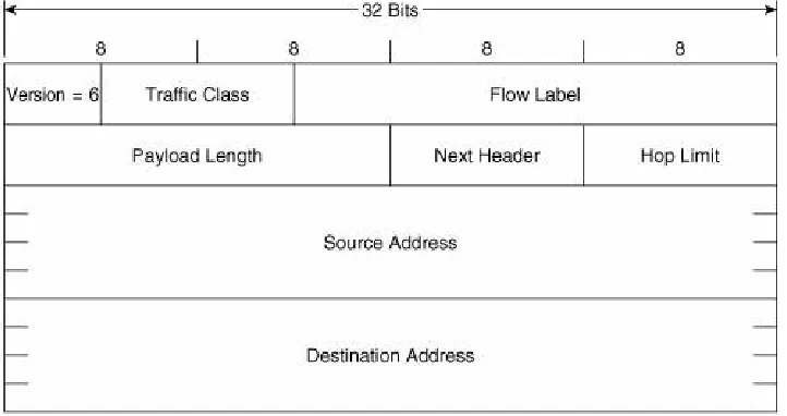
The format of the IPv6 packet header is shown in Figure 2-5. There are some distinct similarities and some differencessome distinct, some subtlewith the IPv4 packet header shown in
Figure 1.2 of the previous chapter.
Figure 2-5. The IPv6 packet header.
Version is, as with the IPv4 header, a four-bit field indicating the IP version. Here, of course, it is set to binary 0110 to indicate version 6.
Flow Label is a field unique to IPv6. The intention of this 20-bit field is to allow labeling of particular flows of traffic; that is, packets that are not just originated by the same source and going to the same destination, but that belong to the same applications at the source and destination. There are several advantages to differentiating flows, from providing a finer-grained differentiated class-of-service treatment to ensuring, when balancing traffic loads across multiple paths, that packets belonging to the same flow are always forwarded over the same path to prevent possible reordering of packets. Flows (or more accurately, microflows) typically are identified by a combination of source and destination address plus source and destination port.
But to identify the source and destination port, a router must look beyond the IP header and into the TCP or UDP (or other transport-layer protocol) header, adding to the complexity of the forwarding process and possibly affecting router
performance. Finding the transport layer header in an IPv6 packet can be especially problematic because of extension headers, described in the next section. An IPv6 router must step through possibly many extension headers to find the transport-layer header.
By marking the Flow Label field appropriately when the packet is originated, routers can identify a flow by looking no further than the packet header. As of this writing, however, the
complete specification of how to use the flow label field is still being debated, and routers currently ignore the field. It
nevertheless holds promise of allowing IPv6 to provide better Quality of Service (QoS) features than IPv4 for applications such as Voice over IP (VoIP).
subtracted from the Total Length field. The IPv6 packet header, on the other hand, is always a fixed length of 40 bytes, and so the single Payload Length field is enough to find the beginning and end of the payload.
Notice also that whereas the IPv4 Total Length field is 16 bits, the IPv6 Payload Length field is 20 bits. The implication here is that because a much longer payload (1,048,575 bytes, versus 65,535 in IPv4) can be specified in this field, the IPv6 packet itself is theoretically capable of carrying a far larger payload.
Next Header specifies which header follows the IPv6 packet header. In this, it is very similar to the Protocol field in the IPv4 header and, in fact, is used for the same purpose when the next header is an upper-layer protocol header. Like that IPv4 field, this field is also eight bits. But in IPv6, the header following the packet header might not be an upper-layer protocol header, but an extension header (again, described in the next section). So the Next Header field is named to reflect this wider range of responsibility.
Hop Limit corresponds exactly, both in length (eight bits) and function, to the IPv4 Time to Live (TTL) field. As you read in
Chapter 1, the original intention of the TTL field was that it would be decremented by the number of seconds a packet is queued in a router during forwarding, but that this function was never implemented. Instead, routers decrement the TTL by one no matter how long the packet is queued (and in modern
networks it is highly unusual for a packet to be queued
anywhere near as long as one second). Therefore, the TTL has always been a measure of the maximum router hops a packet can take on its way to a destination. If the TTL decrements to 0, the packet is discarded. Hop Limit is used for exactly the same, but is named more appropriately for this function.
Noticeably missing from the IPv6 header is a Checksum field like that of the IPv4 header. Given the overall increase in reliability of modern transport mediawireless perhaps being a notable exceptionalong with the fact that upper-layer protocols usually carry their own error-checking and recovery
Extension Headers
Comparing the IPv6 header in Figure 2-5 with the IPv4 header in Figure 1.2, you can see that although the Source and
Destination Address fields are each four times as long in the IPv6 header, the IPv6 header itself is not that much larger than an IPv4 header: 40 bytes for IPv6 versus a minimum of 20 bytes for IPv4. If extensive use is made of the IPv4 Options field, although unusual, the IPv4 header can actually be larger than the IPv6 header.
Also notice that in addition to the Options field, other fields that are not always used, such as those associated with
fragmentation, are eliminated from the IPv6 header. So given its fixed length and exclusion of all fields that do not carry information necessary for the forwarding of every packet, the IPv6 header is both compact and efficient.
But what if you do want to use one of those optional IP features, such as fragmentation or source routing or
authentication? When an optional function is used in IPv6, an
extension header appropriate for the function is added after the packet header. If, for example, source routing, fragmentation, and authentication options are to be used, three extension headers formatted to carry the information needed for each of those functions are added as shown in Figure 2-6. Because of these headers, efficiency is added to IPv6 packets in two ways:
The packet carries only the information required by that individual packet. No unused fields are carried.
Figure 2-6. Extension headers allow IPv6 packets
to carry all the information required for that
packet, but only the information required for that
packet.
[View full size image]
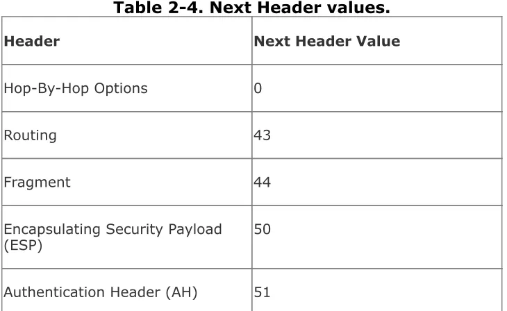
Each extension header, like the IPv6 header, has a Next Header field. So each header tells which header follows it. Table 2-4
shows the currently defined extension headers and their next header values. So, for example, in Figure 2-7, the Next Header value in the IPv6 header indicates that the next header is a Routing extension header (43), that header's Next Header field indicates that the next header is a Fragmentation extension header (44), and so on. The last extension header, AH,
indicates that the next header is a TCP header (Protocol Number 6).
Table 2-4. Next Header values.
Header Next Header Value
Hop-By-Hop Options 0
Routing 43
Fragment 44
Encapsulating Security Payload
(ESP) 50
Destination Options 60
TCP/IP Protocols Protocol number value defined for
that protocol (such as TCP = 6, UDP = 17, OSPF = 89, and so on)
No Next Header 59
Figure 2-7. The Next Header field in the IPv6
header and each extension header specifies
which header follows it.
[View full size image]
The format of each of the extension headers is described in RFC 1883. But briefly, the function of each extension header is as follows:
Hop-By-Hop Optionscarries information that must be
examined by every node along the forwarding path, such as Router Alert and Jumbo Payload options.
Fragmentis used when a packet is fragmented, to provide the information necessary for the receiving node to
reassemble the packet. A significant difference between IPv4 and IPv6 is that only originating nodes can fragment packets; IPv6 routers do not fragment the packets. So originating nodes must either use Path MTU Discovery (PMD) to find the lowest MTU along a path to the
destination, or never produce packets larger than 1280 bytes. PMD is described in the next section. IPv6 specifies that all links on which it runs must be able to support packet sizes of at least 1280 bytes so that originators can use the minimum-size option rather than PMD if they so choose.
Encapsulating Security Payload (ESP) is used when the payload is encrypted.
Authentication Header (AH) is used when the packet must be authenticated between the source and destination.
Destination Options carries information to be examined only by the destination node or possibly by nodes listed in the Routing header.
RFC 1883 also specifies the order in which extension headers, if they are used, should appear. The only hard-and-fast rule here is that if the Hop-By-Hop Options header is used, it must
directly follow the IPv6 header so that it can be easily found by the transit nodes that must examine it. The recommended
extension header order is as follows:
1. IPv6 Header
2. Hop-By-Hop Options
the Routing header must examine this header)
4. Routing
5. Fragment
6. Authentication
7. Encapsulating Security Payload
8. Destination Options (if only the final destination must examine this header)
ICMPv6
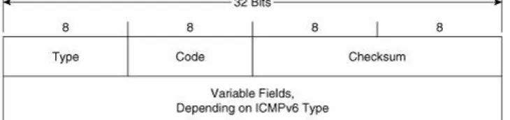
IPv6 requires a control protocol for exchanging and processing error and informational messages, just as IPv4 does. And like IPv4, it uses ICMP to do this. But the ICMP used by IPv6 is not the same ICMP as used by IPv4. Although ICMP for IPv4 has a Protocol Number of 1, ICMPv6 for IPv6 has a Next Header value of 58.
ICMPv6 is specified in RFC 2463. Many of the functions defined in this RFC are the same ones defined for ICMP for IPv4; but there are many ICMP messages, such as Source Quench and Timestamp, that have no equivalent in ICMPv6.
Comparing the ICMPv6 header shown in Figure 2-8 to the ICMP header shown in Figure 1.28, you can see that they are
identical. And like ICMP, ICMPv6 uses a combination of type and code values to identify general types and then subtypes under them. The values defined in RFC 1885 are listed in Table 2-5.
Figure 2-8. The ICMPv6 header format.
Table 2-5. ICMPv6 Message Type and Code fields.
1 DESTINATION UNREACHABLE
0 No route to destination
1 Communication with destination
administratively prohibited
2 Not a neighbor
3 Address unreachable
4 Port unreachable
2 0 PACKET TOO BIG
3 TIME EXCEEDED
0 Hop limit exceeded in transit
1 Fragment reassembly time exceeded
4 PARAMETER PROBLEM
0 Erroneous header field encountered
1 Unrecognized Next Header type
encountered
2 Unrecognized IPv6 option encountered
128 0 ECHO REQUEST
129 0 ECHO REPLY
130 0 GROUP MEMBERSHIP QUERY
131 0 GROUP MEMBERSHIP REPORT
In addition to the basic error and informational functions of ICMPv6, there are mechanisms that use the ICMPv6 messages. For example, the Path MTU Discovery mechanism mentioned in the previous section sends packets of increasing size to a
destination. When the smallest MTU of the links on the path to the destination is exceeded by a given packet size, the packet is dropped and a Packet Too Big message is sent to the source address; the source then knows the smallest MTU on the path. And, as with IPv4, Echo and Echo Reply messages are used by the Ping function.
Neighbor Discovery Protocol
The most distinct characteristics of IPv6 after its increased address space are its plug-and-play features. Neighbor
Discovery Protocol (NDP) is the enabler of these plug-and-play features, using the following functions:
Router Discovery A node can discover, when it is
connected to an IPv6 link, the local routers without the aid of Dynamic Host Configuration Protocol (DHCP).
Prefix Discovery A node can discover, when it is connected to an IPv6 link, the prefix or prefixes assigned to that link.
Parameter Discovery A node can discover parameters such as the link MTU and hop limits for its connected link.
Address Autoconfiguration A node can determine its full address, again without the aid of DHCP.
Address Resolution A node can discover the link-layer addresses of other nodes on the link without the use of Address Resolution Protocol (ARP).
Next-Hop Determination A node on a link can determine the link-layer next hop for a destination, either as a local destination or a router to the destination.
Neighbor Unreachability Detection A node can
determine when a neighbor on a link, either another host or a router, is no longer reachable.
address it wants to use is already being used by another node on the link.
Redirect A router can notify a host of a better next-hop than itself to an off-link destination. The redirect function is a part of basic ICMP functionality in IPv4, but is redefined as part of NDP in IPv6.
NDP messages should always be link-local in scope, and therefore the packets encapsulating them always use either link-local IPv6 addresses or multicast addresses with a link-local scope. To add a further layer of security, the Hop Limit of the IPv6 packet carrying all NDP messages is 255. If one of these packets is received with a Hop Limit less than that value, it means the packet has passed through at least one router, and the packet is dropped. This prevents NDP from being attacked or spoofed from a source not attached to the local link.
NDP Messages
NDP is defined in RFC 2461. It uses ICMPv6 to exchange the messages necessary for its functions; specifically, five new ICMPv6 messages are specified in RFC 2461:
Router Advertisement (RA) messages are originated by routers to advertise their presence and link-specific
parameters such as link prefixes, link MTU, and hop limits. These messages are sent periodically, and also in response to Router Solicitation messages.
Router Solicitation (RS) messages are originated by hosts to request that a router send an RA.
nodes to request another node's link layer address and also for functions such as duplicate address detection and
neighbor unreachability detection.
Neighbor Advertisement (NA) messages are sent in response to NS messages. If a node changes its link-layer address, it can send an unsolicited NA to advertise the new address.
Redirect messages are used the same way that redirects are used in ICMP for IPv4; they have merely been moved from being a part of the base ICMPv6 protocol to being a part of NDP.
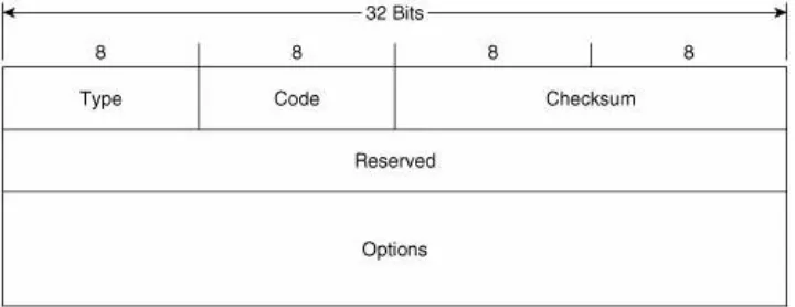
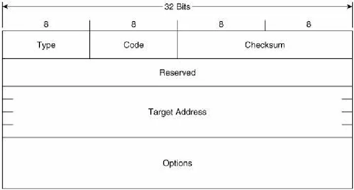
Figure 2-9 shows the format of the Router Advertisement
message. Its ICMPv6 type is 134 and the code is 0. The source address of the IPv6 packet encapsulating the RA is always the IPv6 link-local address of the interface from which the packet originates. The destination address is either the all-nodes
multicast address (FF02::1) if the RA is a periodic transmit, or the link-local address of the soliciting node if the RA is sent in response to a Router Solicitation.
Hop Limit indicates the value of the Hop Limit field that nodes attached to the link should give to any packets they originate on the link. If no Hop Limit is specified by this router, the field is set to all zeroes.
M is the Managed Address Configuration flag. If this bit is set, the originating router is telling hosts on the link to use stateful address autoconfiguration via DHCPv6. If the flag is cleared, hosts on the link should use stateless address
autoconfiguration. Address autoconfiguration is described later in this chapter.
O is the Other Stateful Configuration flag. When set, the
originating router is telling hosts on the link to use DHCPv6 for the acquisition of other link information. The M and O flags can be used together. For example, by clearing the M flag but
setting the O flag, the router is telling hosts to use stateless address autoconfiguration but then consult a DHCPv6 server for other configuration parameters.
maximum value of 18.2 hours.
Reachable Time is used by the Neighbor Unreachability
Detection function of NDP. It specifies the time, in milliseconds, that a node should assume a neighbor is reachable after the node has confirmed reachability of the neighbor.
Retransmit Timer is used by the Address Resolution and
Neighbor Unreachability Detection functions of NDP. It specifies the minimum time, in milliseconds, between retransmitted
Neighbor Solicitation messages.
Possible options that can be carried in the Options field of the RA include the following:
The link-layer address of the interface from which the RA is originated.
An MTU specification for the link.
One or more prefixes assigned to the link. This information is essential to stateless address autoconfiguration, telling hosts on the link what the link prefixes are.
Figure 2-10 shows the format of the Router Solicitation
message. Its ICMPv6 type is 133 and the code is 0. The source address of the IPv6 packet encapsulating the RS is either the IPv6 address assigned to the originating interface or, if no address has been assigned (as would be the case if the originating host is beginning address autoconfiguration), an unspecified address of :: (all zeroes). The destination address is the all-routers multicast address (FF02::2).
The Options field can contain the link-layer address of the originating interface, if it is known. However, the source link-layer address must not be included if the source address of the encapsulation packet is unspecified, such as when the originator is soliciting a router during address autoconfiguration.
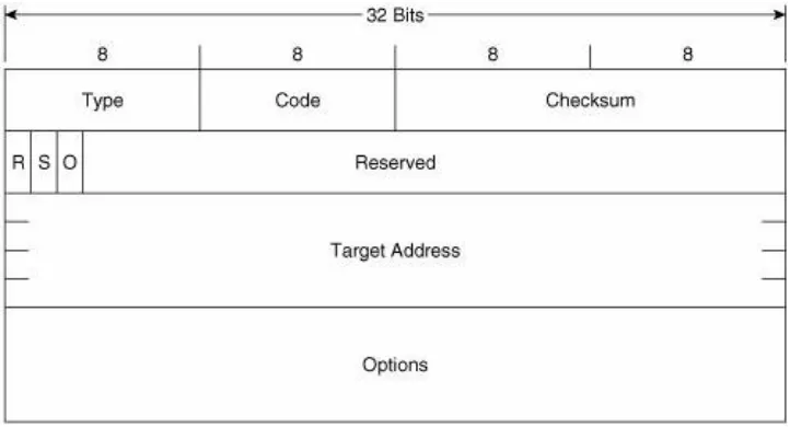
Figure 2-11 shows the format of the Neighbor Solicitation
message. Its ICMPv6 type is 135 and the code is 0. The source address of the IPv6 packet encapsulating the NS is either the IPv6 address assigned to the originating interface or, if the NS is sent for Duplicate Address Detection, the unspecified address of :: (all zeroes). The destination address is either a solicited-node multicast address corresponding to the target address, or the target address.
Target Address is the IPv6 address of the target of the solicitation. The target address is never a multicast address.
The Options field of the NS can contain the link-layer address of the originating interface.
Figure 2-12 shows the format of the Neighbor Advertisement message. Its ICMPv6 type is 136 and the code is 0. The source address of the IPv6 packet encapsulating the NS is always the IPv6 address assigned (or autoconfigured) to the originating interface. The destination address is either the source address of the packet containing the NS to which the NA is sent in response, or the all-nodes multicast address (FF02::1).
R is the Router flag. When set, it indicates that the originator is a router. This bit is used during Neighbor Reachability Detection to detect a router that has changed to a host.
S is the Solicited flag. This bit is set when the NA is sent in response to an NS.
O is the Override flag. When set, it indicates that the
information in the NA should override any existing neighbor
cache entry and update the cached link-layer address. When the O bit is cleared the NA will not override an existing neighbor cache entry.
Target Address is, when the NA is sent in response to a NS, the address in the Target Address field of the NS. If the NA is unsolicited (that is, sent to advertise a change of the
originator's link-layer address), the Target Address is the originator's address.
The Options field of the NA can contain the target link-layer addressthat is, the link-layer address of the NA's originator.
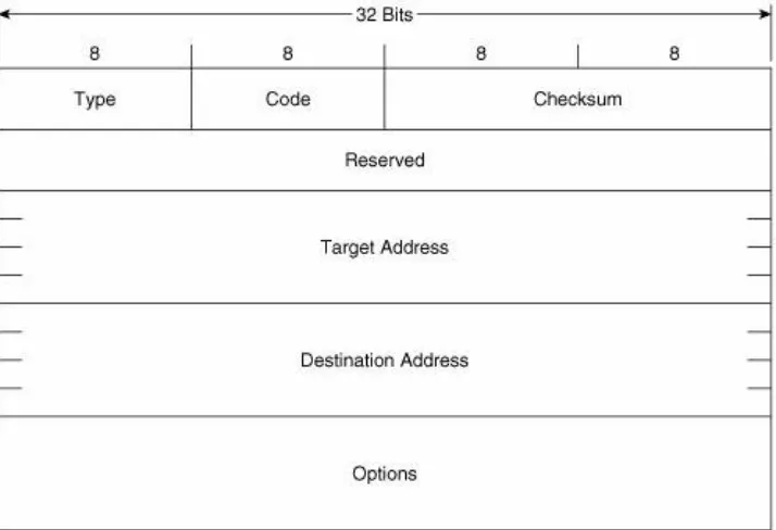
the IPv6 packet encapsulating the Redirect is always the link-local IPv6 address of the interface from which the message is originated. The destination address is always the source
address of the packet that triggered the redirect.
Figure 2-13. The Redirect message format.
Target Address is the address of the better first-hopusually the link-local address of another router on the link.
Destination Address is the IPv6 address of the destination that is redirected to the target address.
The Options field of the Redirect message can contain the link-layer address of the target, and as much of the header of the packet that triggered the redirect, without making the redirect packet exceed 1280 bytes.
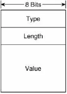
any information, consists of one or more Type/Length/Value (TLV) triplets. Each TLV consists, as shown in Figure 2-14, of an 8-bit Type field specifying the type of information carried in the value field, an 8-bit Length field specifying the length in units of 8 octets of the value field, and the variable length Value field.
Figure 2-14. The format of the TLVs used in the
Options fields of the NDP messages.
Table 2-6 shows the possible values and their associated type numbers. The format of the individual value fields is not
provided in this chapter; consult RFC 2461 for the details on the value fields.
Table 2-6. Value fields and their types.
Type Value
1 Source Link-Layer Address
2 Target Link-Layer Address
3 Prefix Information
5 MTU
Router Discovery
A router makes its presence known, along with any parameters it has been configured to advertise, by periodically sending RAs on its attached links. Presumably the links on which the RA do the most good are broadcast links such as Ethernet, where hosts can receive the RAs and thus learn necessary information about the link.
RFC 2461 specifies that the period between transmissions of RAs should be between 4 and 1800 seconds, with a default of 600 seconds. It also specifies a minimum period between advertisements of RAs with a default of 200 seconds. The advertisements are jittered between the maximum and minimum values to prevent synchronization on a link.
These unsolicited RAs are sent with their source address set to the link-local IPv6 address of the router's interface. The
destination address is the all-nodes multicast address (FF02::1).
Cisco routers automatically send RAs on Ethernet and FDDI interfaces whenever IPv6 is enabled on the router with the command ipv6 unicast-routing. The default interval is 200 seconds, and can be changed with the command ipv6 nd ra-interval. The Router Lifetime of the transmitted RAs is 1800 seconds by default, and can be changed with the command
RAs is 0 (which means unspecified), and can be changed with the command ipv6 nd reachable-time. The Retransmit Timer field is set to a default of 0 ms (unspecified) and can be
changed with the command ipv6 nd ns-interval. The M and O flags can be set with the commands ipv6 nd
managed-config-flag and ipv6 nd other-config-flag, respectively. If you do not want an interface to transmit RAs at all, you can disable them with the command ipv6 nd suppress-ra.
By default, Cisco routers include in the RAs all IPv6 prefixes configured on the originating interface. You can control the prefixes advertised, and parameters associated with those prefixes, with the command ipv6 nd prefix.
Of course, 200 seconds is a long time for a host that has just attached to an interface to wait for an RA so that it can find the routers and learn the link parameters. So when a host first
becomes active on a link, it can send an RS to solicit the immediate transmission of an RA. The source of the RS can either be the unspecified address (::) or the host's link-local IPv6 address. The destination is always the all-routers multicast (FF02::2).
When a router receives an RS, it sends (after a delay of .5 seconds) an RA in response. If the source address of the RS that triggered the RA is a host's link-local address, the RA is unicast to the host using its link-local address. If the source address of the RS was unspecified, the solicited RA is multicast to the all-nodes address.
used.
Address Autoconfiguration
When an IPv6 host first becomes active on a link, it can self-configure its own interface address. The first step in this
process is the determination of the 64-bit Interface ID portion of the address. On broadcast interfaces (where hosts are most likely to appear), a mechanism called MAC-to-EUI64 conversion
is used. Quite simply, this mechanism takes the 48-bit Media Access Control (MAC) address of the interfacewhich can
normally be assumed to be globally uniqueand converts it into a 64-bit Interface ID by inserting a reserved 16-bit value of
0xFFFE into the middle of the MAC address and "flipping" the Universal/Local (U/L) bit of the MAC address to 1 (Universal).
Figure 2-15 illustrates this process. A MAC address,
0000:0B0A:2D51, is to be converted. The first step, shown in binary for easier understanding of what is happening, is to "split" the MAC address in the middle and insert 0xFFFE
between the two 24-bit halves. The address is now 64 bits long. Next, the U/L bit of the original MAC addresswhich is always the 7th bitis flipped from 0 to 1. The resulting address,
0200:0BFF:FE0A:2D51, is now a valid 64-bit Interface ID.
Figure 2-15. MAC-to-EUI64 conversion is used to
create a 64-bit Interface ID from an interface's
Of course, the Interface ID is only half of the IPv6 address; a 64-bit prefix is also required. Recall from Table 2-1 that the link-local prefix is a reserved, well-known value of 0xFF80::/10. Using this as a full 64-bit prefix (0xFF80::/64), it can be added onto the derived Interface ID, and the host now has a complete IPv6 address that can be used for communication with other devices on the same link. For example, combining the link-local prefix with the Interface ID derived in Figure 2-15 gives a link-local address of FF80::0200:0BFF:FE0A:2D51. 2-The following shows an example of a link-local address, in this case from an Ethernet interface "en1" on a Macintosh OS X host. Using the link-local prefix FF80::/10 and a MAC-to-EUI64 conversion, an IPv6 interface derives its link-local address with no help from any other device:
[Jeff-Doyles-Computer:~] jdoyle% ifconfig en1
en1: flags=8863<UP,BROADCAST,SMART,RUNNING,SIMPLEX,MULTICAST> mtu 1300 inet6 fe80::211:24ff:fe23:334e prefixlen 64 scopeid 0x5
inet 10.10.24.13 netmask 0xffffff00 broadcast 10.10.24.255 ether 00:11:24:23:33:4e
supported media: autoselect [Jeff-Doyles-Computer:~] jdoyle%
If the host only needs to communicate with devices on the link, autoconfiguring its link-local address is sufficient. But if it needs to communicate with devices off-link, it needs an address with a wider scopenormally a global IPv6 address. There are two ways it can acquire this address: stateful or stateless address
autoconfiguration.
If a host uses stateful address autoconfiguration, it consults a DHCPv6 server for the necessary address information. It might either be preconfigured to find a DHCPv6 server, or a received RA might have its M flag set telling it to use DHCPv6. DHCPv6, described in RFC 3315, is not much different in its end results than DHCP for IPv4.
Much more interesting is stateless autoconfiguration. With this very simple process, the host acquires one or more link prefixes from the RAs it receives. It then adds the prefix to its previously determined Interface ID, and it now has a globally unique IPv6 address. For example, if the host from Figure 2-15 received an RA advertising a prefix of 3FFE: 1104:404:1::/64, it would add that prefix to its Interface ID for a global address of 3FFE:1104: 404:1:0200:0BFF:FE0A:2D51.