UAV CAMERAS: OVERVIEW AND GEOMETRIC CALIBRATION BENCHMARK
M. Cramer a 1, H.-J. Przybilla b, A. Zurhorst c
a Institute for Photogrammetry (ifp), Stuttgart University, Geschwister-Scholl-Str. 24D, 70174 Stuttgart, Germany - [email protected]
b Department of Geodesy, Bochum University of Applied Sciences, Lennershofstr. 140, 44801 Bochum, Germany - [email protected]
c aerometrics, Landwehrstraße 143, 59368 Werne, Germany – [email protected]
ICWG I/II
KEY WORDS: UAV camera, geometric calibration, stability, benchmark, image formats
ABSTRACT:
Different UAV platforms and sensors are used in mapping already, many of them equipped with (sometimes) modified cameras as known from the consumer market. Even though these systems normally fulfil their requested mapping accuracy, the question arises, which system performs best? This asks for a benchmark, to check selected UAV based camera systems in well-defined, reproducible environments. Such benchmark is tried within this work here. Nine different cameras used on UAV platforms, representing typical camera classes, are considered. The focus is laid on the geometry here, which is tightly linked to the process of geometrical calibration of the system. In most applications the calibration is performed in-situ, i.e. calibration parameters are obtained as part of the project data itself. This is often motivated because consumer cameras do not keep constant geometry, thus, cannot be seen as metric cameras. Still, some of the commercial systems are quite stable over time, as it was proven from repeated (terrestrial) calibrations runs. Already (pre-)calibrated systems may offer advantages, especially when the block geometry of the project does not allow for a stable and sufficient in-situ calibration. Especially for such scenario close to metric UAV cameras may have advantages. Empirical airborne test flights in a calibration field have shown how block geometry influences the estimated calibration parameters and how consistent the parameters from lab calibration can be reproduced.
1. INTRODUCTION
The UAV based image recording is a now-established data acquisition method in photogrammetry and geodesy. In addition to the request to capture data in reasonable imaging block geometry (typically images are flown as highly overlapping blocks) and corresponding evaluation, the choice of the camera system is important as the camera is the primary sensor from which the later products (e.g. 3D object points, 3D point clouds) are derived. In the meantime there is a variety of cameras used in UAV based scenarios. In the first beginnings these systems were almost entirely from the so-called consumer segment: Compact cameras, mirrorless system and / or bridge cameras (Digital Single Lens Mirrorless, DSLM) as well as classic Digital Single Lens Reflex cameras (DSLR). Recently, however, high-quality medium-format cameras have increasingly been offered for use on UAVs. In addition, multi- / hyperspectral systems offer extended application possibilities that extend the range of visible spectrum to near and thermal infrared. UAV based remote sensing is definitely one of the most emerging UAV application scenarios.
If one focuses on the geometrical reconstruction of 3D objects, i.e. following the more classical “geometry-based” photogrammetric point of view, the question of selecting the suitable camera is essential: which camera will fulfil my application in agreement with my project-related accuracy requirements? There is an ongoing debate on the need for geometric pre-calibration from labs and/or (moveable) calibration targets, ultimately culminating in the question for a (photogram-)metric camera system. Others fully rely on the potential of in-situ calibration, which is the standard tool provided by extended bundle adjustment using additional
1 Corresponding author
parameters to refine the camera’s geometry from the image data itself.
This paper will give an overview on the current scenario of cameras, often used in UAV applications. Its focus is on the geometrical calibration of these cameras. A total of 9 different camera systems has been evaluated for their geometric properties. In order to compare and reproduce results, the tests have been made in well-defined test fields, namely a terrestrial 3D geometrical lab calibration field and a 3D test field, where the cameras have been flown after. It should be mentioned, that due to time and organizational issues not all of the cameras, which have been analysed in the lab, already have been flown in the airborne test field. Due to the fast consumer product cycles some of the investigated systems have already been re-placed by their successors.
This paper can be seen in connection of the work from Meißner et al. (2017) – to be submitted to this UAV-g conference – where the analysis of radiometric performance of UAV based cameras is discussed. Some of the cameras investigated from geometrical point of view here also were radiometrically analysed by Meißner et al. (2017).
2. UAV BASED CAMERAS – OVERVIEW AND
CALIBRATION ASPECTS
In principle, today’s UAVs offer the possibility to carry different kind of camera systems, although the providers often recommend specific systems or products. Limiting factor often is the maximum-take-off-weight (MTOW) of the carrier, which is characteristic for the specific UAV. For the past the MTOW was limited to 5kg, at least for those, who would like to get a more flexibly general permission to fly all over the country (for
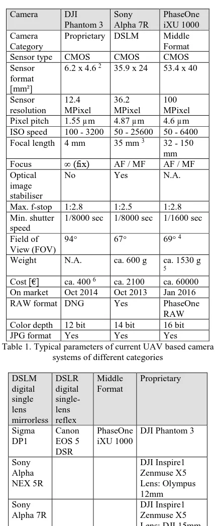
Germany only). This MTOW was recently increased to 10kg, which somewhat reduced the weight constraints on the payload, assuming the UAV is capable to lift-off this additional weight. The market of digital cameras as such is highly dynamic; there are several hundred new releases and further developments of existing systems every year. Most cameras, however, are common to the general photographers (mass-)market where stable and reproducible camera geometry is not the primary goal in development. In order to classify, available camera systems can be grouped into the following categories: proprietary cameras (like DJI systems on Phantom or Inspire platforms), system or bridge cameras (alternatively called digital single lens mirrorless DSLM, like Sony Alpha series), standard digital single-lens reflex DSLR cameras and middle/large format camera (like PhaseOne iXU series) (Cramer 2016, Przybilla 2017). Some relevant technical data for selected systems can be seen from the following Table 1.
As the classical photogrammetry has its clear focus on the precise geometric modelling of 3D objects, the geometric calibration and stability is one important part of the process flow. From this point of view, almost all UAV camera systems belong to the group of "partially metric cameras" since the sensor matrix realizes a defined image coordinate system and the distortion parameters of the interior orientation can be assumed to be largely constant, while focal length and principal point position represent variable elements. From this, the necessity for camera calibration is obvious, which most often is carried out simultaneously within the bundle block adjustment of project data itself – this is called self- / or in-situ calibration which allows the optimal estimation of camera calibration as part of the project itself. The necessary preconditions during the UAV flight are described by Przybilla et al. (2015) as well as Gerke & Przybilla (2016). Remaining optical and mechanical inadequacies of the cameras, as well as user errors during operation, however, cannot be modelled in the evaluation process and may impose further accuracy losses.
3. GEOMETRIC CALIBRATION PERFORMANCE
TEST – BENCHMARK
3.1 Lab calibrations
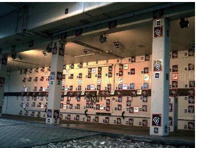
Calibrations by using well defined (3D) test fields offer the possibility to test the geometrical behaviour of a camera system over a longer period of time or under variable operating conditions. The 3-dimensional test field of the HS Bochum used here has an extension of approx. 14m x 3m x 3m and consists of approx. 500 spatially distributed, coded and non-coded targets (Figure 1a-b). The image acquisition during the calibration takes place via convergent imagery taken from 180° varying viewing directions and from different heights. In order to decouple exterior and interior orientations and to precisely determine principal point position, as well as of affinity and non-orthogonality parameters, the data set includes 90°, 180° and 270° tilted images. The described calibration configuration is depicted in Figure 1c. The calibration is carried out as part of a bundle block adjustment using the software Aicon 3D-Studio. Typically 70 images were taken per calibration run. The number of images for the DJI system calibration was little less, which is due to the more complex handling, as the camera cannot be separated from the drone itself, which limits the handling when taking the tilted / rotated imagery. The Aicon 3D-Studio implements the standard Brown additional parameter physical
21/2.3“ sensor
3 Voigtländer Skopar 35/2.5 4 with HC 3.5/35mm optic
model, which consists of corrections of focal length, principal point, radial- and tangential distortions and affinity and shear components. All of the points are extracted automatically, using ellipse fitting.
Proprietary DSLM Middle Format
Table 1. Typical parameters of current UAV based camera systems of different categories
Table 2. Evaluated UAV cameras
5 Schneider-Kreuznach fast sync 55mm f/2.8
6 costs including standard optic and gimbal (as of Nov 2016)
Figure 1a. 3D test site at Bochum University of Applied Sciences (overview)
Figure 1b. Different types of coded targets
Figure 1c. Example for the calibration configuration
Within the following, nine different camera systems (see Table 2) have been evaluated in this calibration environment. As the geometry of calibration blocks is very similar and comparable – similar camera stations have been realized for all of the different systems – the calibration results can be compared directly. In order to check for the stability and repeatability of camera parameters, the same camera was calibrated multiple times. The system is completely switched-off and restarted between calibrations. In addition, for some of the cameras (due to their availability) the multiple calibration epochs were extended over a period of several days.
The Figure 2 shows the stability of principal point components and principal distance forthe nine mentioned cameras from Table 2. Except two systems, all cameras were calibrated in 4 different epochs. The first calibration always was supposed to be the reference epoch, the remaining thus indicating variations of the three geometric parameters of interior orientation over time, between calibration epochs. As it can be seen, the changes in the parameters are obvious for all of the investigated systems. These
deviations can be interpreted as an indication of the optical-mechanical instability of the camera. Still, looking in detail one may see little differences in results. Concerning DSLM cameras the changes for DP1 and Ricoh systems are well below ±5µm for all components, where the DP1 seems to be a little more stable than the Ricoh, which might be due to the fixed lens of DP1. This is followed by the PhaseOne, representing the middle format sector. The Canon EOS represents the DSLR class and shows the largest variations; here the principal distance changes for more than 60µm for the last two calibration epochs. In between you find the two Sony systems. For the Sony NEX 5R the focal length changed by -12µm in the fourth calibration epoch.
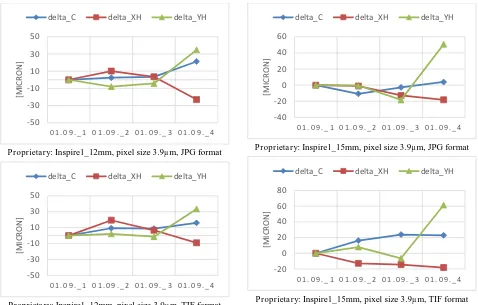
Interesting to note, the proprietary DJI Phantom 3 system shows quite small variations (below 4µm only). Even though the four epochs were all taken at the same day for DJI calibration, these only small changes might also be due to the fixed mounting of lens and camera body as this camera system cannot be changed by the user. Obviously the Phantom 3 proprietary system is quite close to the concept of (photogram-)metric camera. This especially becomes obvious comparing the stability of Phantom 3 camera with the DJI Inspire systems, all being calibrated on one single day only. Still the Inspire shows much larger variations not only in the focal length but also in principal point. Please notice the different scaling of the axis of ordinates in Figure 2. One additional aspect was analysed for the DJI systems. The influence of image formats within the calibration. Here the calibration result from original raw format (converted into TIF) was compared to the results from JPG images, directly generated by the camera. Such different image formats influence the calibration result which can be seen for all of the DJI cameras. The parameter variation is larger in case JPG imagery is used, even though it is only the output image format changed, i.e. the image block geometry is exactly the same. Obviously the export of images in different format does not only change the format of the file only, but additional geometrical corrections are applied by camera firmware. Using the JPG formats in calibration, the standard physical parameter model only less precisely fits to the images, compared to the results from calibration using the TIF imagery. The differences are significant; about 1/10 of a pixel for all the three tested DJI camera installations, as depicted in Table 3. In addition, these differences also might be due to the inevitable compression effects, when using JPG formats, which will affect the quality of tie point matching. Unfortunately the camera supplier does not give any more details on what is modified when converting RAW images to JGP format. Table 3 shows the variations of sigma0 values after bundle adjustment of test field calibration blocks for the different cameras. The mean sigma0 is obtained from the 3-4 calibration runs of each camera system. This value reflects the precision of intersection of rays of an observation with unit weight. As the block geometries are very close and all image observations are considered with similar weightings (as derived automatically using the same software) the sigma0 can be used to compare results.
DSLM: Sigma DP1, pixel size 7.8µm, JPG format
DSLM: Sony Alpha NEX 5R, pixel size 4.8µm, JPG format
DSLM: Sony Alpha 7R, pixel size 4.9µm, JPG format
DSLM: Ricoh GXR, pixel size 5.5µm, JPG format
DSLR: Canon EOS 5 DSR, pixel size 4.14µm, JPG format
Middle Format: PhaseOne iXU 1000, pixel size 4.6µm, TIF format
Proprietary: DJI Phantom 3, pixel size 1.5µm, JPG format
Proprietary: DJI Phantom 3, pixel size 1.5µm, TIF format
Camera Format sigma0 [µm] sigma0 [pix] Table 3. Estimated quality (sigma0 after bundle adjustment) of
test field calibration
There are clear differences visible. Quite some cameras, all in the DSLM camera group except the DJI Phantom 3, perform around 0.2µm which refers to around 0.05 – 0.15 pix depending on the original pixel size of the systems. This number indicates the quality of point mensuration and, in addition, how well the calibration model fits the physical reality of image formation. Within the group of DSLM/DSLR systems the Sony Alpha 7R and the Canon EOS perform little less, whereas the Sigma DP1 performs best, besides the DJI Phantom 3 (using TIF format), the latter belonging to the group of proprietary systems. If the sigma values are given in pixel, the Sigma DP1 is the best DSLM camera here. This might be due to the unique approach of RGB image acquisition, as the system is based on the FOVEON chip, which is not used by any of the other systems. As the FOVEON technology allows to capture all three colour channels for each individual pixel, the use of Bayer filters and following
de-mosaicking, which is standard for all the remaining cameras, is not necessary here. The influence of image de-mosaicking is discussed and comprehensively analysed in Meißner et al. (2017). As mentioned, the Phantom 3 (using TIF) shows very good performance, not only in the group of proprietary DJI systems, further confirming the previous assumption that this camera is already close to the concept of metric camera design. As it can be seen from the parallel TIF and JPG analyses as done for the DJI cameras, the use of uncompressed RAW image data (later converted to TIF) is of advantage and should be recommended. Unfortunately most of the cameras need more time for the capturing of RAW image formats, which in way limits the flights especially when high forward overlap is required and the flight speed cannot be decreased accordingly.
3.2 UAV flight in-situ calibrations
The self- or in-situ calibration is quasi-standard for triangulation of UAV image blocks. In almost all adjustments the additional camera parameters are considered as one group of unknowns (Jacobsen et al. 2010, Cramer et al. 2017). What is not sufficiently addressed by many users are the special requirements on the underlying geometry of the block when in-situ calibration is applied. Reliable calibration is only possible with a suitable image acquisition configuration (Przybilla et al., 2015). Reliable calibration means that the camera parameters are determined physically correct i.e. decoupled as best as possible from the remaining unknowns of the exterior orientation parameters. This especially is of concern, when calibrations should be transferred to other mission sites. As it was described previously, in terrestrial lab calibration scenarios special configurations and camera tilting are realized to get those parameters de-correlated, which is not possible in real airborne scenarios. Still, as off-nadir angles in UAV applications tend to become larger than in classic Proprietary: Inspire1_12mm, pixel size 3.9µm, JPG format
Proprietary: Inspire1_12mm, pixel size 3.9µm, TIF format
Proprietary: Inspire1_15mm, pixel size 3.9µm, JPG format
Proprietary: Inspire1_15mm, pixel size 3.9µm, TIF format
Figure 2. Changes of interior orientation parameters between calibration epochs, results obtained from 3D test site
-50
airborne photogrammetric imaging, this already supports the block geometry and the in-situ calibration.
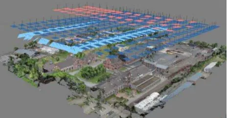
Figure 4 exemplarily shows the flight arrangements in the UAV test field "Zeche Zollern" Dortmund, covering an area of approx. 215 x 315m. It is a former hard-coal facility which now is converted into an industrial museum. Thus, the area contains several diverse pit buildings. The two mine head towers surpass the terrain with their height of about 40m. The figure shows a typical configuration, i.e. as flown in the context of DJI Inspire camera (12mm) calibration flights (GSD approx. 2 cm). In addition to the standard nadir arrangement (REGULAR), the block has been supplemented by a cross (CROSS) and / or convergent (OBLIQUE) arrangement in different variants. The parameters of the interior orientation (IORI) have been determined differently: unified – using one set of IORI for all images or separate – using a separate set of IORI for each of the sub-block arrangements, which describes the effect of turning the camera on and off while changing the battery of the UAV. A total of 46 regularly distributed signalized points is available serving as ground control (GCP) or check points (ChP), respectively. GCPs were taken into account into adjustment with an accuracy of 5mm.
Figure 5a shows the multiple calibration of a Zenmuse X5 equipped with an Olympus lens (M. Zuiko Digital ED 12mm, see (Przybilla, 2017)) as part of the DJI Inspire 1 UAV. The changes in terrestrial 3D test field calibration (4 epochs, already discussed and shown in Section 3.1) are compared to self-calibrating AT from Zeche Zollern flights (versions R-C Unified, R only). Figure 5b represents the same but now for using a DJI Phantom 3 with its integrated fix focus 4mm lens camera. These two DJI installations – so far – are the two only systems, which in the context of this research have already been evaluated from both terrestrial and airborne calibration tests.
While the first calibration sequences from terrestrial test site calibration show comparatively small deviations (see Figure 2 for enlarged view), there are clear changes in IO parameters, especially in focal length, when it comes to the airborne in-situ approach. As discussed the different epochs of terrestrial test field calibrations were in a direct temporal context and the block geometry is comparable in all four cases (see Fig. 1c). The last two epochs in Fig. 5a/b depict the results from the in-situ flights. The clear jump in the focal length estimate is obvious. It reaches more than 450m (115pix) for the Inspire and about 100m (65pix) for the Phantom 3. These deviations can be partially seen as an indication of the optical-mechanical instability of the camera. Still, this effect is present for both cameras. From terrestrial calibrations the Phantom 3 performed significantly more stable than the Inspire system. Even though the change in focal length for Phantom 3 is less compared to the Inspire, it is still obvious and not really expected from the terrestrial runs. Besides real change in the focal length, this effect could also be due to the fact, that the in-situ flights do not offer this special calibration scenario image block configurations. It should be mentioned, that the airborne scenarios did not use additional GNSS-observed perspective centre coordinates, which add additional geometrical strength into the bundle to de-couple focal length variations from unknown height components of camera stations. Even though some of the UAV already offer precise differential phase GNSS observations, most of the systems provide single point code GNSS solutions only. This may help for initialization of the block, but will not allow for precise GNSS support within self-calibration.
Figure 4. Different calibration scenarios in test field Zollern: Nadir normal (REGULAR): dark blue - Nadir cross (CROSS): red - Convergent (OBLIQUE): light blue
Figure 5a. Changes of the interior orientation parameters, DJI Inspire 1 with Zenmuse X5 using Olympus M. Zuiko Digital
ED 12mm lens
Figure 5b. Same as Fig. 5a, but for DJI Phantom 3
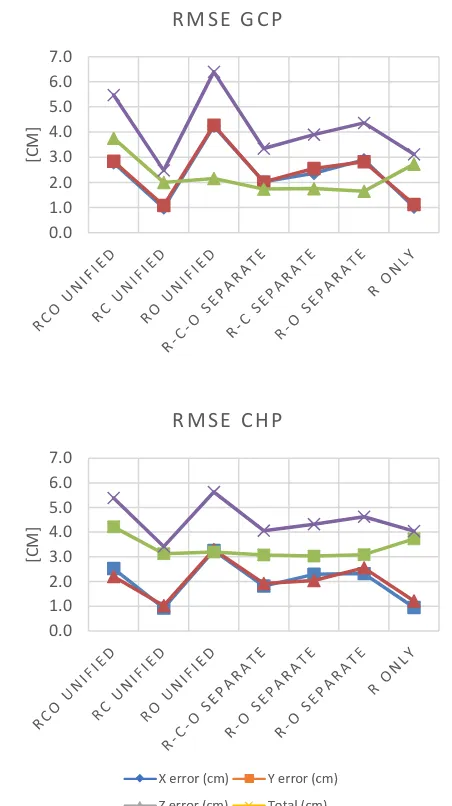
The influence of the different image block configurations on the quality of the in-situ calibration is derived from object coordinate residuals as shown in Figure 6 (DJI Inspire 1) and Figure 7 (DJI Phantom 3). About half of the signalized object points are used as control or check points here. The residual deviations (RMSE) are derived from 22 control points (GCP) and 23 check points (ChP). Only images in JPG format are considered here. As it can be seen from the figure legend, different block combinations as introduced above are investigated here. The residuals should be compared to the mean GSD, which is approx. 2cm in both cases. The upper part of both figures show the residuals from GCPs, the lower from ChPs. GCP residuals for sure are influenced by the weighting of control point observations, which was 5mm here. If one looks for Figure 6 (results from the DJI Inspire system) clear differences are visible for the different combinations. The best results are derived from the nadir looking cross-pattern flown block in connection with the determination of one common set of interior orientation (R-C Unified). Due to the slightly different flying heights above ground (the cross pattern is flown about 30% higher than the regular flight lines), scale-dependent effects can be decoupled from constant offsets. Due to the nadir image geometry, a good matching between overlapping imagery
is ensured, which has a positive effect on the block geometry and the determinability of the parameters. Against this background, the further combination with the oblique block should actually provide even better results - similar to the standard configuration for the classical camera calibration as discussed before. This is not the case, however, if the version R-C-O unified is compared with R-C unified. The oblique angle of the O-block was selected to approximately 45°, resulting in a less strong matching of the oblique images with the nadir images of the R-C blocks. If one set of orientation elements is estimated separately for each of the image groups with the use of the oblique images, the object space accuracy improves somewhat but does not reach the accuracy of the R-C block only combination. In addition, this does not support the original motivation to stabilize the block by adding additional images. In the last block variant, the calibration is only determined from the images of the nadir block (R only). The accuracy is only slightly worse (about 10%) than those of the R-C block combination. This shows that the calibration from just one regular image set-up is often sufficient, if there is enough height difference at the object site. This is well-known from the early days of test-field calibration (i.e. Torlegård 1967). Figure 6. Effects of the image acquisition and calibration
configuration on residual deviations (RMSE) at 22 ground control points (see top) and 23 check points (see bottom). UAV:
DJI Inspire 1
Figure 7. As figure 6, but with UAV: DJI Phantom 3
0.0 1.0 2.0 3.0 4.0 5.0 6.0 7.0
[C
M]
R M S E G C P
0.0 1.0 2.0 3.0 4.0 5.0 6.0 7.0
[C
M]
R M S E C H P
It is interesting to see, that the larger differences based on the different block configurations are not such visible for the DJI Phantom 3 results. As expected, this system performs better than the Inspire above. Different to the Inspire, the total error from ChP differences is within 1.5 x GSD for the Phantom 3 – compared to the 2-3 x GSD performance of Inspire.
4. CONCLUSIONS AND OUTLOOK
Nearly all of the cameras commonly used in UAV applications show significant differences when comparing laboratory and test field calibrations. An a priori laboratory calibration is therefore not necessary and helpful for most of the current camera systems. The use of non-compressed raw images is recommended, especially concerning the DJI cameras: The JPG format is designed to be preconfigured at the factory and does not record the real image errors, in addition to compression effects. The calibration of the camera with the methods of in-situ or self-calibration is sufficient but only works if the block has sufficiently good block geometry. As a rule, all blocks with overlapping parallel flight lines or 360° circular image blocks with a large image overlap (the latter can be realized through copter flights) should fulfill these prerequisites. Possibly it is helpful not to start in-situ calibration from zero values, but to use the previous calibration as an approximation. Especially the distortion of the camera system changes little.
In the in-situ calibration tests presented here, the combination of two nadir blocks in cross-flight configuration with slightly different flying heights provides the best results. An additional added oblique block does not significantly affect accuracy. This is contrary to expectation, but could be expected as long the different blocks are not connected properly via tie point matches. This problem is also known from evaluations of large-format oblique camera systems (e.g., Vexcel Imaging Osprey). A slightly inclined recording direction of 10° - 20° (referring to the Nadir) might reduce/solve this problem.
If unconventional block geometry (for example, individual flight lines for corridor applications) is present, a best pre-calibrated camera must be requested. Ideally, this camera is calibrated in a close temporal and spatial context nearby the mission area (i.e. by using a test area) and these parameters are then adopted. For such applications, cameras with the most stable camera geometry possible are preferred. In some circumstances, proprietary cameras, with fixed optics and fixed focus can be advantageous; alternatively specially developed cameras should be considered for these applications, which brings back the discussion where the use of fully metric cameras might become necessary. There are ongoing system developments or already prototype systems, which (sometimes partially) fulfill above metric requirement. This for example was comprehensively presented and discussed at the last annual meeting of the German Society of Photogrammetry, Remote Sensing and Geoinformatics (DGPF) in March in Würzburg / Germany, where cameras optimized for the photogrammetric use in UAV environments have been presented as invited. It was confirmed that such systems are of advantage, when it comes to unconventional block geometries, for example in case of long corridor surveys. In addition those systems will guarantee precise time synchronization which is of major importance when directly measured precise GNSS/inertial exterior orientations are considered in processing. Finally global shutter technology, low-noise imagery and other specs will further support the efficient and accurate photogrammetric product generation.
ACKNOWLEDGEMENTS
Thanks a lot for supporting the project to all colleagues who work together in the “German UAV Group” – every group member knows who belongs to it!
REFERENCES
Cramer, M., 2016. Welche ist am besten? – Ein paar Anmerkungen zur Auswahl von Kamerasystemen in der UAS-Luftbildphotogrammetrie. In: UAV2016 – Vermessung mit unbemannten System. Schriftenreihe des DVW, Band 82, S. 97 – 118, Wißner-Verlag, Augsburg, ISBN: 978-3-95786-067-5
Cramer, M., Przybilla, H.-J.; Meißner, H. & Stebner, K., 2017. Kalibrierung und Qualitätsuntersuchungen UAV-basierter Kamerasysteme. In: 156. DVW-Seminar "UAV 2017 – Unmanned Aerial Vehicles 2017", Stuttgart, Germany, online access http://shortlinks.de/pv16
DJI Innovations, 2017: DJI-Website, http://www.DJI.com/de, Letzter Zugriff: 23.06.2017
Gerke, M. & Przybilla, H.-J., 2016: Accuracy analysis of photogrammetric UAV image blocks: influence of onboard RTK-GNSS and cross flight patterns. Zeitschrift für Photogrammetrie, Fernerkundung und Geoinformation (PFG). Heft 1, 2016
Jacobsen, K., Cramer, M., Ladstädter, R., Ressl, C., Spreckels, V., 2010. DGPF-Project: Evaluation of Digital Photogrammetric Camera Systems – Geometric Performance. Zeitschrift für Photogrammetrie, Fernerkundung und Geoinformation (PFG). Heft 2, 2010
Kraft, T., Geßner, M., Meißner, H., Przybilla, H.J., Gerke, M., 2016. Introduction of a photogrammetric camera system for RPAS with highly accurate GNSS/IMU information for standardized workflows. The International Archives of the Photogrammetry, Remote Sensing and Spatial Information Sciences, XL-3/W4, 71-75, 2016
Meißner, H., Cramer, M. & Piltz, B., 2017. Benchmarking the optical resolving power of UAV based camera systems, submitted to this UAV-g 2017 conference, Bonn, Germany
Przybilla, H.-J., Reuber, C., Bäumker, M. & Gerke, M., 2015: Untersuchungen zur Genauigkeitssteigerung von UAV-Bildflügen. – 35. Wissenschaftlich-Technische Jahrestagung der DGPF 24: 45–54.
Przybilla, H.-J., 2017: Kameras für UAS - Eine Marktübersicht. In: 156. DVW-Seminar "UAV 2017 – Unmanned Aerial Vehicles 2017", Stuttgart, Germany, online access
http://shortlinks.de/pv16
Torlegård, K., 1967. On the determination of interior orientation of close-up cameras under operational conditions using three dimensional test objects, Doctoral Thesis, Roy. Inst. Technol. Stockholm, 100 pages.