SEARCHING LOST PEOPLE WITH UAVS: THE SYSTEM AND RESULTS OF THE
CLOSE-SEARCH PROJECT
P. Molinaa, I. Colominaa, T. Vitoriab, P. F. Silvac, J. Skaloudd, W. Kornuse, R. Pradesf, C. Aguilerag
(a) Institute of Geomatics, Generalitat de Catalunya & Universitat Polit`ecnica de Catalunya, Castelldefels, Spain (b) Asociaci´on de la Industria Navarra, Pamplona, Spain
(c) DEIMOS Engenharia, Lisbon, Portugal
(d) ´Ecole Polyt´echnique F´ed´eral de Lausanne, Lausanne, Switzerland (e) Institut Cartog`afic de Catalunya, Barcelona, Spain (f) Direcci´o General de Protecci´o Civil, Barcelona, Spain (g) European GNSS Supervisory Authority, Brussels, Belgium
KEY WORDS:UAV, search-and-rescue, thermal imaging, integrity, reliability, INS, GNSS
ABSTRACT:
This paper will introduce the goals, concept and results of the project named CLOSE-SEARCH, which stands for ’Accurate and safe EGNOS-SoL Navigation for UAV-based low-cost Search-And-Rescue (SAR) operations’. The main goal is to integrate a medium-size, helicopter-type Unmanned Aerial Vehicle (UAV), a thermal imaging sensor and an EGNOS-based multi-sensor navigation system, including an Autonomous Integrity Monitoring (AIM) capability, to support search operations in difficult-to-access areas and/or night operations. The focus of the paper is three-fold. Firstly, the operational and technical challenges of the proposed approach are discussed, such as ultra-safe multi-sensor navigation system, the use of combined thermal and optical vision (infrared plus visible) for person recognition and Beyond-Line-Of-Sight communications among others. Secondly, the implementation of the integrity concept for UAV platforms is discussed herein through the AIM approach. Based on the potential of the geodetic quality analysis and on the use of the European EGNOS system as a navigation performance starting point, AIM approaches integrity from theprecisionstandpoint; that is, the derivation of Horizontal and Vertical Protection Levels (HPLs, VPLs) from a realistic precision estimation of the position parameters is performed and compared to predefined Alert Limits (ALs). Finally, some results from the project test campaigns are described to report on particular project achievements. Together with actual Search-and-Rescue teams, the system was operated in realistic, user-chosen test scenarios. In this context, and specially focusing on the EGNOS-based UAV navigation, the AIM capability and also the RGB/thermal imaging subsystem, a summary of the results is presented.
1 INTRODUCTION
The use of Unmanned Aerial Vehicles (UAVs) —more in gen-eral, Unmanned Aerial Systems (UASs)— for SAR operations is not new and has been traditionally fed by developments made in other fields. The main driver of UAV technology has been (and still is) the military field and this is because the nature of military developments is fairly overlapping SAR needs. As a example of that, we recall the UAVs used in the Iraq and Afghanistan wars were deployed to find people trapped in New Orleans buildings devastated by Hurricane Katrinas flood waters. Those platforms were equipped with thermal imaging systems to detect the body heat of storm survivors. A second example was the use of rotary-wing UAV platforms providing on-site imagery from the nuclear incident in Fukushima. More recently, a field that is increasingly putting effort on UAV development is Geomatics: the potential of those light-weight, easy-deployable platforms to quickly provide aerial and/or ground, good quality imagery is huge. A clear ex-ample of this interest raised within the geomatic community is the recent acquisition of Gateway, a provider of lightweight UAVs for photogrammetry and rapid terrain mapping applications, by Trimble. Indeed, the multi-application of the UAV potential to other fields, such as SAR, shall not be neglected. And even if [the lack of] regulations have been the stopper of the final jump to commercial applications, the willingness of regulators seems finally positive on pulling the trigger. As stated in the Institute of Navigation newsletter in winter 2011, ”the United States trans-portation secretary must develop a comprehensive plan to safely accelerate the integration of civil UAS into the national airspace system as soon as practicable, but not later than September 30th, 2015.”
Thinking on the general SAR context, when a small plane crashes in a remote area, or a fishing boat is lost at sea, or a hurricane devastates a region, or simply a person gets lost while he/she was hiking, SAR teams must scan vast areas in search for victims ev-idence or wreckage. For this purpose, UAVs equipped with ther-mal or other sensors can be programmed to fly predefined search patterns at low altitudes —30 m to 150 m—, transmitting real-time imagery back to a ground station via a data link. Although less spread in Europe than in North America or Australia, it can be stated that the use of UAS for the so-called ”wilderness SAR” is rapidly evolving (Goodrich et al., 2007). As the project tar-geted at search missions —not rescue missions—, the proposed system was designed to be integrated in the SAR context just as one more piece of the search workflow. For this reason, the inter-action with users (civil protection services, firefighters, sea res-cue) was permanent to steer the technical development towards user needs. Starting from the distress message containing the ap-proximate area in where a person is lost, the loop closes back to the user by providing a georeference (accurate to few meters) of the lost person, identified through combined thermal and optical images: the rest is left for the rescue teams.
ultra-safe systems. The target objective was to demonstrate that EGNOS-based UAV control is feasible by using a closely cou-pled EGNOS/RINS/BA concept and to assess the safety degree offered by such a solution, in terms of navigation integrity. We believe that the use of integrity for non-conventional platforms (cars, trains, UAVs..) is novel and may be of mandatory imple-mentation in line with the upcoming UAV regulations previously mentioned.
In order to provide the reader with a general view of the system and a particular view of the subsystems and the results, section 2 describes the system architecture and its key components, sec-tion 3 provides a descripsec-tion on the use of integrity for UAVs and on this particular platform, navigation system and application; and finally section 4 provides results on the imaging and naviga-tion components. Finally, chapter5 compiles the lessons learned within the project, which we hope would be of valuable use for those willing the explore the uses of UAS in related applications.
2 THE CLOSE-SEARCH PROTOTYPE: A SYSTEM OF SYSTEMS
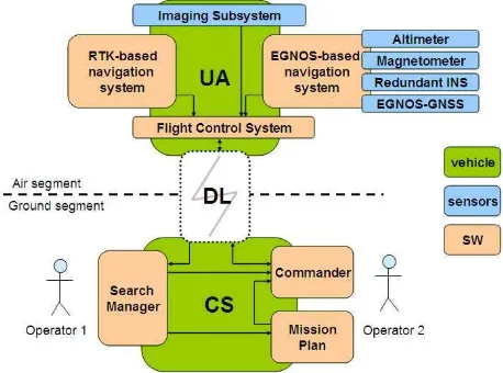
Figure 1 depicts the system architecture, which is basically de-scribed through theairandgroundsegments. As it can be seen, the prototype developed is the result of an imaging, navigation, communication and mission planning integration work: a sys-tem of syssys-tems. Next subsections detail the various subsystems in place.
Figure 1: The CLOSE-SEARCH system architecture
2.1 Unmanned aerial platform and control station
In a UAS, the necessary —yet not sufficient— components are the UAV and the Ground Control Station (GCS). The partner re-sponsible for these two components (Asociaci´on de la Industria Navarra, AIN) contributed to the project with their UAR-35, a rotary-wing platform of about 3 m length, 75 kg MTOW and 18 HP. The Flight Control System (FCS) is an in-house devel-opment by AIN, as well as the Real-Time Kinematic (RTK) nav-igation subsystem combining IMU and magnetometer for the at-titude determination. RTK navigation is characterized by pro-viding centimeter-level accuracy: therefore, the existing navi-gation subsystem was used as a reference for the validation of the EGNOS-based navigation subsystem, which was a genuine project development. As this vehicle can carry up to 30 kg pay-load, it is an ideal platform to integrate other redundant or com-plementary systems, such as remote sensing instruments or other navigation sensors.
The GCS is mounted on a 4WD van and is composed of three computers and the appropriate SW components to command and control the UAV and to display the images from the imaging subsystem. In this way, two operators are able to monitor and command the UA and operate the search mission. The mission planning can be performed off-line and loaded into the GCS, but corrections to the waypoints and actions can be done in real mis-sion time. The project used high-precimis-sion, LiDAR-based (0.5 points/m2
) Digital Surface Models (DSMs). In figure 2, the UAV and the GCS are presented on its final CLOSE-SEARCH version during the final test campaign in March 2012.
Figure 2: The CLOSE-SEARCH UAV and GCS
2.2 Line-Of-Sight and Beyond Line-Of-Sight communica-tions
In relation to the communication subsystem, two data links are established in the prototype: the command-and-control data link, consisting on a downlink to transmit the telemetry data and an uplink to send commands to the UAV; and the payload data link, consisting on a downlink to transmit remote sensing outcome (in that case, thermal and optical images).
The CLOSE-SEARCH primary communication strategy is based on wireless networking technology, WiFi, which has suitable per-formance in terms of range and bandwidth. This subsystem pro-vides a direct link between the UA and the CS and its quality of service depends of Signal-to-Noise Ratio (SNR), which worsens with distance or obstacles. This Line-Of-Sight (LOS) communi-cation architecture performs adequately within a range of 5 km.
belong), the WiMAX coverage is provided by base stations dis-tributed throughout a region, covering 95% of the territory. Al-though with lesser coverage than satellite-based communication, WiMAX technology as a potential candidate for BLOS commu-nication on UAVs has been tested within the project with posi-tive user feed-back. For more information, reader is referred to http://www.wimaxforum.org.
2.3 Remote sensing component: thermal and RGB
The main goal behind the remote sensing component in CLOSE-SEARCH is to find a lost person through his/her body heat, com-plementing the thermal image with an color image (much more intuitive for an operator to identify objects). In open-air environ-ments, especially focusing on mountain or cold scenarios, this idea makes sense a priori. Nonetheless, previous work on com-bined thermal and color imagery in UAVs (Rudol and Doherty, 2008) already points at the difficulty on identifying people in thermal images with trained algorithms due to low resolution of these cameras, halos around thermal targets, etc. In our project, the intention was to solve this problem by means of human intel-ligence: that is, human identification through images is left to a SAR operator who constantly stares at the screen —this requires softer computational burden and benefits from trained humans, always more reliable than any algorithm.
The remote sensing component integrated on the system is com-posed of two sensors: a thermal camera —Raytheon 2000B, 320 x 240 pixels, 33o x25o Field of View (FOV)—, sensitive on the 8-12µm spectral range; and a color camera —Sony CCD CM-3120CDM, 582 x 500 pixels—. Although other lenses were tested, the results presented in this paper were obtained with a 35ox30oFOV for the RGB camera. With no a-priori calibration, both cameras were mounted down-looking on a carbon fiber sheet attached to the payload frame using cup-style isolators. These provide vibration isolation for frequencies as low as 10 Hz and exhibit low transmissibility at resonance.
2.4 The navigation concept: EGNOS and RINS for UAVs
UAV-based missions in the field of Geomatics (but extensible to SAR) generally consist on following a route, defined by applica-tion requirements, and remotely sense the environment to finally on/off-line analyze and interpret the outcome. From a naviga-tion, guidance and control standpoint, the system shall perform according to several requirements: endurance, sense-and-avoid and other. Yet, two of these key requirements aresafety (keep-ing the platform ’far’ from ground or known obstacles in order to avoid collisions) and theapplication performance(ranging from centimeter-grade accuracy for photogrammetric applications to few meters for surveillance applications).
Indeed, SAR demands for a high level safety and, at the same time, belongs to the ’coarser’ category in terms of application performance. As it would be simply too risky to fly with a stand-alone GNSS-based solution, the role of GNSS augmentation sys-tems is key for UAV missions: using the satellite-based augmen-tation system EGNOS, the real-time horizontal and vertical per-formance reaches 2 and 3 m, 2σ-level, respectively. Even if RTK would deliver much better positioning performances, its depen-dency on static GNSS setups and communication links may not be fully suitable for SAR missions, which usually demand for go-&-fly actions anywhere at anytime, having to eventually assume communication drops. In addition, the integrity information de-livered by EGNOS (which is lacked by the RTK system), in com-bination with a tactical-grade IMU (LN200) and a Barometric Al-timeter (BA), has been studied within the project to establish and
assess safety levels for UAV navigation in SAR missions (Molina et al., 2011). Chapter 3 is devoted to the integrity/reliability con-cept developed within the project and its results.
Last but not least, the study of the use of a Redundant Inertial Navigation System (RINS) in substitution of tactical-grade IMUs has been carried out for unmanned platforms. The use of low-cost, small RINS may even be proofed as a ’must’ for UAVs: re-ductions in costs and increases in payload are targeted in civilian UAV applications.
3 INTEGRITY FOR UAVS
Indeed, the civil aviation community has been so far the only field linking the safety specifications, well-defined by the Interna-tional Civil Aviation Organization (ICAO), and the performance of the navigation systems. The Minimum Operational Perfor-mance Standards (MOPS) (RTCA, 2001) is the result of these efforts and not much reading of that document is required to re-alize that the integrity concept is claimed to be the key safety enabler. As safety is a universal concept, the natural discussion on how should integrity be understood outside the civil aviation field (in which very stringent SoL requirements hold) has raised recently, and has boosted up since huge markets as car navigation and Location-Based Services (LBS) have become a reality. Cargo transportation, public services, like trains, buses, ships, etc. are definitely willing to benefit from integrity i.e. safety in naviga-tion, but may even not consider its use due to the lack of over-all adoption and too-stringent requirements based on worst-case risk definitions (Pullen et al., 2011). Within CLOSE-SEARCH, the exercise of understanding and implementing integrity for a UAV in a particular type of application like SAR has been carried out, based on very fundamental geodetic concepts like reliability and precision. The goal of this chapter is to explain the integrity concept and its implementation within the project: the so-called Autonomous Integrity Monitoring (AIM).
3.1 Integrity as the safety measure
There are two ways of understanding integrity, confidence- or risk-wise, which are essentially complementary: if one is 99% confident that a system is performing correctly, there is also a 1% risk that it is performing incorrectly. A confidence-based defi-nition of integrity is given in the ICAOs GNSS Standards And Recommended Practices (SARPS): ”Integrity is a measure of the trust which can be placed in the correctness of the information supplied by the total system. Integrity includes the ability of a system to provide timely and valid warnings to users.” An ac-cepted alternative risk-based definition claims: ”Integrity risk is the probability of providing a signal that is out of tolerance with-out warning the user in a given period of time.” More in detail into de definition, three principal concepts shall be understood: the Alarm Limit (AL) is the error tolerance not to be exceeded without issuing an alert to the user; the Time-To-Alarm (TTA) is the maximum permitted duration between the onset of a failure and an alert being issued at the user side; and the Integrity Risk (IR), which is the probability of a miss-detected out-of-tolerance event not warned within the TTA. This triad of values should be application or platformad-hoc: for example, ALs defined for the APV-I category in landing approach in civil aviation are defined as 50 m and 40 m in the horizontal and vertical components re-spectively, withIR= 2·10−7. These values do not make much
platforms, which are not larger than a couple of meters and fly at low altitude —as in our case. Thus, GNSS satellite-based aug-mentation systems (the so-called SBAS, like EGNOS or WAAS) are much of a resource to improve accuracy in navigation for any platform, but less of a tool to increase integrity for all users (at least, in a direct way) —EGNOS and WAAS are certified for landing approaches in civil aviation, but cannot be certified for other applications due to the lack of regulated safety frames. It is then interesting to provide a new frame for those willing to use the SBAS integrity service for their platforms. Previous work in the frame of this project (Molina et al., 2011) aimed at developing new requirements adapted to our mission and platform. After the final test campaigns, results with real-data are presented to assess the previously stated requirements and provide corrections on the integrity frame definition for UAVs in SAR missions.
3.2 Geodetic reliability and precision-based integrity moni-toring
The AIM concept understands integrity in two ways: on one side, there is a need to deal with sensor faults, generally speaking, that may falsify the quality of navigation. To do so, those should be detected, removed and, in case that removal is not possible, warn-ings should be sent to the user. On the other side, considering the situation in which faults have been detected, a bound of the [a-priori unknown] true error shall be provided to the user as a measure of safety in navigation.
For the first part, we recall the quality concepts introduced by Willem Baarda, published between 1967 and 1976, providing a consistent, rigorous and systematic framework to the quality of geodetic networks and extensible to any least-squares based es-timation procedure. Indeed, navigation is one more application of least-squares and so the geodetic quality concepts can also be used. Three steps are fundamental on the geodetic quality theory: statistical testing to remove outliers and model errors, bounding the effect of undetected outliers and ensuring the estimated pre-cision to be above certain limits. As published in recent work within this project (Molina et al., 2011), (Molina and Colomina, 2012) steps 1 and 2 are materialized through regression diagnos-tics and a particular, suitable selection of the type I and II errors.
For the second part, the use of the EGNOS system is a key enabler of precision-based integrity as the faults related to the GNSS Signal-In-Space (SIS) are duly detected and removed by the EG-NOS ground segment. By decoding the EGEG-NOS messages and using its information into the appropriate pseudo-range model, the user is provided with an accurate i.e. GNSS-outlier free so-lution. When considering sensor hybridization with IMUs and other sensors, the same assumptions should hold; that means, sensor measurements shall not be affected by outliers, either by applying geodetic techniques as described in the previous step or either by considering that they are outlier-free. On this stage of the project, the second assumption is considered for the EG-NOS/IMU/BA configuration. Note that local effects such as ther-mal noise or multipath are not included on the EGNOS correc-tions and then should be tackled when navigating in harsh envi-ronments (urban canyons, forests...). For simplicity matters, they are not considered in this approach.
In this situation, the estimation of the position variance,σH, σV for horizontal and vertical subspaces respectively, is considered to berealistic, that is, the errors follow a distributionN(0, σH) andN(0, σV). Now, in order to minimize the risk, the variances are scaled to a level compatible to the IR, yielding the well-known formula:
P LH,V =KH,V ·σH,V
wherePH,V are the protection levels,KH,V are the scaling fac-tors andσH,V are the horizontal and vertical variances. A com-prehensive background on the derivation of the scaling values KH,V in relation to the IR can be found in (Roturier et al., 2001).
4 RESULTS OF THE FLIGHT TEST CAMPAIGN
The final testing phase in CLOSE-SEARCH started with labo-ratory testing of the various subsystems to be put in place. Its integration into the overall system was performed and finalized with a flight test campaign. This campaign consisted on short flights (15 minutes) in which the integration and overall results of the various system components were assessed: navigation, imag-ing, communications, etc. An example of one test performed in Los Arcos, Navarra, on February29th
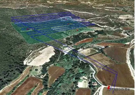
, 2012, can be found athttp://bit.ly/I6LkqV. Finally, due to the high involve-ment of the local Civil Protection authorities on the project, a final set of flight tests were conducted to realistically approach the usual scenarios of search missions, in terms of deployment of resources, mission configuration, nature of the incident area, etc. In order to demonstrate how the system would be used on a search mission, a route was defined over the area in which a hu-man target was placed aiming at its recognition through the imag-ing subsystem and its georeferencimag-ing with suitable accuracy. The selected area was of an approximate size of 500m x 300m, and a patrol scan pattern was defined for the scanning mission (similar to the typical photogrammetric missions). The platform flew at 4 m/s speed in the straight, parallel lines at 40 m above ground level: for these imaging sensors, the Ground Sampling Distances (GSD) were 7.4cm x 7.4cm for the thermal camera and 4.2cm x 3.8cm for the RGB camera respectively. Figure 3 depicts the route designed with the Mission Planner: pin-pointing on pre-viously loaded cartography and DSM, the waypoints are gener-ated in Excel or KML format and loaded into the commandment software, which is in charge of providing control and guidance instructions to the UA platform.
Figure 3: Route executed for a search mission in CLOSE-SEARCH.
RGB camera (in which the person is also clearly seen), a comple-mentary and more natural view of the situation is provided. The combination of RGB and thermal images has been pointed out by users as an nice-to-have feature, specially in cases where hints might be useful (clothing, person’s objects...) To finally close the loop within the SAR workflow, the system was requested to per-form real-time georeferencing of potential targets. This capabil-ity was implemented through ray-tracing, taking advantage of the high-precision DSMs, in a way that the target would be georefer-enced just by a click of the operator in the image. The particular results on georeferencing accuracy obtained during several tests within the test campaign are around 10 m in easting and northing, which has been defined as sufficient (by far) for the rescue teams. Summarizing, a CLOSE-SEARCH operator is provided with the capability of answering to key questions in search missions (is it a person? is he/she alive?) by means of combined RGB/thermal vision; besides the provided situation awareness, the operator is able to determine positions of targets within few meters and thus activate rescue missions with very focused objectives -instead of combing vast areas, ground coordinates are provided with just few meters of error.
Figure 4: A person sensed by the RGB/thermal sensors. Video version athttp://bit.ly/HN3efY
With respect to the navigation results, the accuracy of the EGNOS-GNSS/INS/BA was assessed by means of the comparison against the RTK-solution. For this purpose, the mean, standard deviation and Root Mean Square Error (RMSE) of the difference of both solutions were computed. Results on two different flights from the test campaign are compiled in??: Test 1 was a short test (15 minutes) and Test 2 was the flight depicted in Figure 4.
As it can be seen, the results on position are in every case below 2 m (horizontal) and below 3 m (vertical) errors, (1σ-level). There-fore, they are fully compliant with the EGNOS performance spec-ification. In addition, the standard deviation of the differences show that the variations are in the order of 1.5 m, and further analysis has revealed that the oscillations of the EGNOS-based solution with respect to the RTK solution are of low frequency (less than 1 Hz) —this demonstrates that the work load of the con-trollers is not dramatically increased and, therefore, the EGNOS-based solution is suitable for control tasks.
Test 1 Test 2
East North Height East North Height
Mean -0.56 0.12 -0.62 -0.82 -0.24 1.35
Std Dev 1.07 1.34 0.71 1.06 1.72 1.46
RMSE 1.21 1.35 0.94 1.34 1.74 1.99
Table 1: Navigation results: Test 1
In relation to the AIM capability, the goal was to assess if the es-timated precision of the parameters was realistically “protecting” the UAV from the actual error —this is, in fact, the essence of
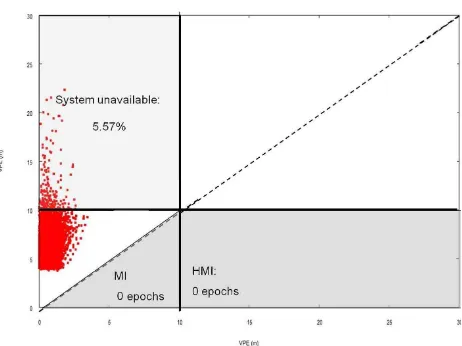
precision-based integrity. Figure??and??depict comparisons of the true error (EGNOS-based solution versus RTK solution) and the computed PLs on Test 2. Note that the PL computation corresponds to anIR= 10−3. The Stanford diagram plots are
generally used in assessment of false alarms and missed detec-tions, as it happen to be the case in generic quality control. In this case, a missed detection is understood as the true error be-ing larger than the protection value offered by the system. As it can be seen in these results, this is never the case. On the other side, false alarms are considered to happen when a PL is above an AL but the true error is below both the PL and AL. In integrity language, the system is declared unavailable (cannot be used in compliance with the safety specification). Indeed, the false alarm event declaration requires the selection of a desired availability degree or, in other words, the particular election of ALs. In view of the application requirements described in 3, the HAL and VAL are set to 10 m and, as shown in the pictures, the achieved system availability is of around 95%.
Figure 5: Stanford diagram comparing the true error and the pro-tection level on the horizontal subspace.
Figure 6: Stanford diagram comparing the true error and the pro-tection level on the vertical subspace.
5 LESSONS LEARNED AND FUTURE WORK
• Hard requirements on mission operations: The three famous
words that describe the UAV nature (dull, dirty and dan-gerous) also hold when describing SAR missions —that is why somehow its combination simply fits. SAR users ask for machines that operate at any time of the day (also at night) in a continuous way during long periods of time and in adverse weather conditions. This is maybe the most criti-cal challenge for UAV manufacturers willing to explore the SAR community. Within the project, a short demonstration of a night flight was performed (its report can be found in http://bit.ly/IcyuXn).
• The use of EGNOS as a substitute of RTK-based solutions:
Nowadays, RTK is the most common GNSS navigation so-lution implemented in UAVs. It is true that the lack of regu-lations may have framed actual UAV operations into very controlled scenarios, with restrictions to visual LOS and flying height. But the contact with SAR users taught us that their willingness is beyondsimpleoperations: navigat-ing behind mountains, or at several hundreds of kilometers away, or using mobile control stations are just few examples on how RTK systems would simply fail to meet continuity requirements. On the opposite, SBAS solutions, as EGNOS, offer acceptable performances with no dependency on local conditions, static setups or communication links. In addi-tion, the use of integrity may be push the start button for regulating safe operations in any open-air environment.
• Updated high-precision DSMs for mission planning: one of
the critical issues on UAV operation certifications is sense-and-avoid capabilities. On one side, it is demanded that a UAV can detect unexpected objects and safely react in con-sequence. And on the other side, ground obstacles (basi-cally, man-made infrastructure) shall not be damaged by any UAV operation. For that, the use of high-precision LiDAR-based DSMs was considered on the Mission Plan compo-nent. One aspect that raised discussion was the need of those DSMs to contain updated information about existing infras-tructures (powerlines, buildings, etc.) —the project then identify requirements to cartography providers to enable a complete reliability concept for UAVs (updated databases plus navigation integrity) which, in the future, shall be com-plemented with sense-and-avoid mechanisms.
• Miniaturization and improvement of RGB and thermal
cam-eras: Indeed, technology goes smaller and smaller —also sensors on the visible, infrared bands. This is in line with the miniaturization process that UAVs also experience, and smaller payloads require for smaller equipment and sensors. Due to the degree of maturity on the optics field, the perfor-mances of small cameras can achieve centimeter-level GSDs shooting at acceptable frequencies (lower than 1 Hz). In ad-dition, and of interest for surveillance applications, generic infrared sensors (from thermal to night vision) are reaching an advanced performance level. The results shown here are just a starting point for further investigation on thermal vi-sion.
• Multi-use platform to exploit the concept versatility: Along
the project, meetings with the user community were car-ried out and many other applications were pointed out as potential and interesting candidates for UAV-based systems. Some of those were related to agriculture, forest fire man-agement, aerial pollution control, traffic control or sea search missions.
• UAV dynamics are different: Actually, UAV motion is quite
constrained in small or medium-size rotary-wing UAVs: high
speeds are usually not achieved, pitch and roll values are usually kept near zero and the hovering capability leads to smoothness in flight phase transition. Nonetheless, the plat-form engine (1 cylinder, 2 stroke air-cooled) operating at full power (18 HP) is a source of high frequency, high am-plitude vibrations, and these vibrations do severely affect the IMU measurements. Efforts have been put within the project on IMU modelling for highly vibratory environments and much work is still left to achieve optimal sensor fusion per-formances.
REFERENCES
Goodrich, M., Cooper, J. L., Adams, J., Humphrey, C., Zeeman, R. and Buss, B. G., 2007, 2007. Using a mini-UAV to support wilderness search and rescue: Practices for human-robot team-ing. Safety, Security and Rescue Robotics proceedings 2007 pp. 1-6.
Molina, P., Colomina, I., 2011. Integrity Aspects of Hybrid EGNOS-based Navigation on Support of Search-and-Rescue Missions With UAVs. Proceedings of the ION GNSS 2011, September 19-23, 2011, Portland, OR.
Molina, P., Colomina, I., 2012. Looking into Navigation In-tegrity for UAVs from a Geodetic Perpective. Proceedings of the Eurpean Calibration and Orientation Workshop, February 8-10, 2012, Castelldefels, Spain.
Pullen, S., Walter, T., Enge, P., 2011. SBAS and GBAS Integrity for Non-Aviation Users: Moving Away from Specific Risk. ION GNSS 2011. Proceedings of the 2011 International Technical Meeting of The Institute of Navigation, January 24-26, 2011, San Diego, CA.
Rudol, P., Doherty, P., 2008. Human Body Detection and Geolo-calization for UAV Search and Rescue Missions Using Color and Thermal Imagery. IEEE Aerospace Conference, March 1-8 2008, Big Sky, MT.
Roturier, B., Chartre, E., Ventura-Travesset, J., , 2001. The SBAS integrity concept standardised by ICAO. Application to EGNOS. Proceedings of the ION GNSS 2001, September 11-14, 2001, Salt Lake City, UT.
Radio Technical Commission for Aeronautics (RTCA), 2001. DO-229C: Minimum operational performance standards for GPS and WAAS airborne equipment.
ACKNOWLEDGEMENTS