MISALIGNMENT CALIBRATION OF ULTRACAM D AND XP
S. Malihi
a, *, M. Maboudi
b, M. Pourmomen
a aFlight Dep., National Cartographic Centre, Tehran, Iran- (malihi, pourmomen)@ncc.org.ir
bIslamic Azad University, Qazvin Branch, Qazvin, Iran- [email protected]
KEYWORDS: IMU-GPS- Digital Aerial Camera- Aerial Triangulation-Sensor Orientation.
Abstract:
Digital aerial cameras are near to become the predominant sensor for photogrammetric image acquisition. The technology of GPS and IMU integrated with a digital aerial camera is a complex procedure of aerial photography with possibility of decreasing number of necessary ground control points (GCPs) for aerial triangulation (AT). Moreover, direct georeferencing, which uses calculated parameters by GPS/IMU directly, is undertaken for a range of projects.
In this regard determination of the geometric relationship between GPS, IMU and camera geometry is a significant factor. Also compensation of camera rotations during the flight, which is carried out by stabilizer, plays a principle role for its successful operation. This paper will discuss calculation of 3 requisite rotational connecting parameters of geometry of camera and GPS/IMU and revise the effect of height on them.
Introduction
Using advantages of digital aerial camera including omitting scanning, higher spatial, spectral and radiometric resolution opens a new horizon to photogrammetry and as a result to surveying and positioning.
Aerial triangulation (AT) is a classical method of producing spatial data which is tolerant to suboptimal data processing. When it is supported by GPS and IMU, Exterior Orientation (EO) parameters are produced and as a result reducing number of GCPs and increasing reliability and accuracy of the photogrammetry block are achieved (Kremer and Kruck, 2003).
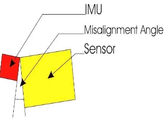
On the other hand, direct georeferencing, which uses EO parameters for photogrammetric data processing, brings large benefits for some projects like orthophoto, producing maps with medium and small scales. This approach doesn’t need any GCPs nor tie points; nonetheless, the boresight parameters are comprised misalignment angles and shift parameters. Misalignment angles which determine the attitude differences between the image sensor coordinate system and the IMU coordinate system (Figure1 (IGI, 2006a)) should be calculated and applied to orientation of the sensor. In order to measure these parameters a special field has to be flown by a specific pattern (Wegman, 2003).
Figure 1: Misalignment angles
This paper presents two experiments of calculating misalignment rotations for two digital cameras including UltraCam XP, D, in different heights and tries to revise effects of this parameter on the rotations.
Designing Test Flight
One pre-condition for direct georeferencing with GPS and IMU is pre-determined misalignment rotations. In order for fulfilling this aim a test site of 40 signalized GCPs from static GPS surveys, which covers 6 km2 and placed in Khur/Isfahan/Iran, is prepared. The accuracy of these points is better than 1 cm. The site is composed of urban texture, hillside and desert.
International Archives of the Photogrammetry, Remote Sensing and Spatial Information Sciences, Volume XXXIX-B1, 2012 XXII ISPRS Congress, 25 August – 01 September 2012, Melbourne, Australia
577
With each of 2 digital cameras UltraCam XP and D, 3 flights in different heights and areas are made. For UCXP, flights are done in 3 Ground Sampling Distances (GSD) 5, 10, 15 cm and for UCD in 3 GSDs 7, 10, 15 cm. Focal length of UCXP is 100.5 mm and UCD is 105.2 mm, also pixel sizes are 6 and 9 micron, respectively.
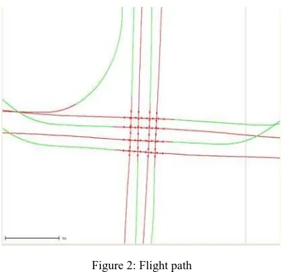
The test flights _as shown in figure 2_comprises 4 parallel strips crossed by 4 other parallel strips (4×4). The photos in each block have a forward overlap of 80% and sideward overlap of 60%.
For whole of the flights IMU-Family d (256.15 Hz) consists of a dual frequency GPS receiver is used. In addition, CCNS4/Aerocontrol systems (IGI, Kreuztal, Germany) with PAV30 for UCD and GSM3000 for UCXP are employed. The latest systems are camera stabilizers which adjusted rotations during flight to some extent as table 1(IGI, 2006b; Leica, 2002) shows. Figure 3 depicts corrected rotations during flight with UCD and GSD=10cm.
PAV 30 GSM300
Pitch ±5° ±8.4°
Roll ±5° ±6.2°
Drift ±30° ±25°
Table 1: Limits of PAV30 and GSM3000 for adjusting rotations
Figure 3: Corrected rotations of camera during flight
In order to come to a perfect result, before taking off, aircraft must not move for 2 minutes owing to IMU initialization. Furthermore, plane should fly alternate left and right turns (IGI, 2006a).
Measurement of Misalignment Parameters
For calculating misalignment rotations, GPS data is processed with help of 2 base stations' coordinates inside the block and GDOP better than 2.5, and combined with IMU data. RMSs of the results, which are EO parameters, are better than 1 cm for positions and 0 .01 degree for rotations. Next, this data, image coordinates and GCPs' information are used as input for combined bundle adjustment. Results for both cameras are presented in tables 2, 3. Sigma naught, which is the overall accuracy of each AT calculations, is employed as weight to compute rotational parameters of boresight.
GSD=5 cm GSD=10 cm GSD=15 cm
Roll +0.2613 +0.2436 +0.2410
Pitch +0.0834 +.0876 +.0873
Yaw +0.0683 +.0616 +.0618
Sigma naught
1.4 0.1 0.8
Table 2: UCXP Misalignments in degree
GSD=7cm GSD=10 cm GSD=15cm
Table 3: UCD Misalignments in degree Figure 2: Flight path
International Archives of the Photogrammetry, Remote Sensing and Spatial Information Sciences, Volume XXXIX-B1, 2012 XXII ISPRS Congress, 25 August – 01 September 2012, Melbourne, Australia
Assessment of Results and Conclusion
The attitude differences between the IMU and the image coordinate systems are independent of GSD and as a result image scale and are more or less stable. Higher Sigma naughts in smaller GSDs imply this fact that flights in low heights suffered from instability and consequently their observations deteriorate.
References
IGI co., 2006a. Aerooffice user manual v.5, Kreuztal, Germany.
IGI co., 2006b. GSM3000 manual, Kreuztal, Germany.
Kremer, J., Kruck, E., 2003. Integrated Sensor Orientation-
Two Examples to show the potential of Simultaneous GPS/IMU and Image Data Processing, ISPRS Proceedings, 2003.
RC30 Aerial Camera System, Leica, Atlanta, USA, 2002.
Wegmann , h., 2003. Image Orientation by Combined AAT with
GPS and IMU, ISPRS Proceedings, XXXIV, part1
Acknowledgement
The authors would like to thank Aerial Triangulation Dept. of National Cartographic Centre, Ms. JaafarAghai and also Mr. Zaree for data used in this paper and for the excellent cooperation.
International Archives of the Photogrammetry, Remote Sensing and Spatial Information Sciences, Volume XXXIX-B1, 2012 XXII ISPRS Congress, 25 August – 01 September 2012, Melbourne, Australia