TOWARDS A NEW ARCHITECTURE FOR AUTONOMOUS DATA COLLECTION
T. J. Tanzi a , Y. Roudier b, L. Apvrille a, * a
Institut Mines-Telecom, Telecom ParisTech, LTCI CNRS, 06410 Biot, France - (tullio.tanzi, ludovic.apvrille)@telecom-paristech.fr b
EURECOM, 06410 Biot, France - [email protected]
KEY WORDS: Unmanned Aerial System, Autonomy, Communications, Architecture, Validation, Real-time
ABSTRACT:
A new generation of UAVs is coming that will help improve the situational awareness and assessment necessary to ensure quality data collection, especially in difficult conditions like natural disasters. Operators should be relieved from time-consuming data collection tasks as much as possible and at the same time, UAVs should assist data collection operations through a more insightful and automated guidance thanks to advanced sensing capabilities. In order to achieve this vision, two challenges must be addressed though. The first one is to achieve a sufficient autonomy, both in terms of navigation and of interpretation of the data sensed. The second one relates to the reliability of the UAV with respect to accidental (safety) or even malicious (security) risks. This however requires the design and development of new embedded architectures for drones to be more autonomous, while mitigating the harm they may potentially cause. We claim that the increased complexity and flexibility of such platforms requires resorting to modelling, simulation, or formal verification techniques in order to validate such critical aspects of the platform. This paper first discusses the potential and challenges faced by autonomous UAVs for data acquisition. The design of a flexible and adaptable embedded UAV architecture is then addressed. Finally, the need for validating the properties of the platform is discussed. Our approach is sketched and illustrated with the example of a lightweight drone performing 3D reconstructions out of the combination of 2D image acquisition and a specific motion control.
* Corresponding author
1. INTRODUCTION
UAVs or drones can enable data acquisition in situations where the access conditions are too dangerous or too difficult for humans, notably during natural disasters, or for fastidious and repetitive data acquisition tasks. UAVs are currently being used in various contexts: entertainment (video), civilian (crop monitoring, mapping, etc.) or military (reconnaissance missions, etc.). While UAVs are usually remotely controlled, their usage will significantly evolve with the introduction of robotic platforms and their autonomy-supporting mechanisms. For example, during intervention and rescue missions, the efficiency of rescuers in 'hostile' situation (flooded areas, areas destroyed by an earthquake, etc.) will be improved only if such devices do not monopolize their attention. The use of such remote acquisition systems should not direly increase the additional human resources required to control these drones, thereby again pleading for autonomous features. UAVs will also need to take decisions about the flight or the operation of the payload in the absence of a precise knowledge of the terrain or exact flight conditions, and subsequently reassess them. Only a handful of existing systems based on automated navigation guided by GPS, like the senseFly system (Ackerman, 2013), already exhibit self-guidance to ensure repetitive tasks in a reliable way. A direct consequence of autonomy is that the system should equally address safety issues, so as not to endanger human beings or goods in its vicinity.
The detection and monitoring of the impact of natural disasters [Guha-Sapir, 2013], on which we especially focus, are already mainly performed by space borne and air borne systems relying on radio and optical instruments. Optical instruments are quite useful for a number of missions, but due to their limitations (i.e. no observation at night or in the presence of a cloud cover), other payloads are being developed. Radio observations on the
other hand are for instance available 24/7 and are relatively insensitive to atmospheric conditions: these are therefore particularly useful during the “Response phase” of the disaster management cycle when information must be delivered to the disaster cell with a as short as possible delay (Wilkinson, 2010), (Tanzi, 2011), (Lefeuvre, 2013). This pleads for generic UAV platforms yet able to safely adapt to specific missions, and to operate diverse payloads in optimal conditions, both performance- and constraint-wise.
This paper discusses challenges and approach in the design and validation of drone architectures able to flexibly adapt to diverse remote data acquisition tasks, endowed with autonomy, notably in their navigation, yet retaining enough assurances to minimize risks inherent to such systems.
2. AUTONOMY AND ITS CONSEQUENCES
2.1 Autonomy and system architecture
Especially due to energetic constraints, the system architectures of autonomous UAVs should be as simple as possible, yet adapted to its task and safety-enabled, especially when operating close to human beings. This requires a better cooperation between subsystems. The UAV should notably take decisions according to its energy consumption (and its remaining energy) to better plan its mission. The data acquired by the payload may be exploitable for navigation and for mission planning; however, exploiting those data may require important computing capabilities possibly unavailable onboard.
wind, or because of the attitude of the drone which has changed to avoid an unpredictable obstacle, or even because the terrain following induces too many attitude variations. Again, a tighter integration between the different subsystems of the UAV may help address such issues. For instance, if the navigation system has sensors to detect such undesired movements, it would be possible to notify the payload when to acquire data optimally and how to assemble those data. However, the data related to these movements are generally inaccessible to the payload in today’s architecture.
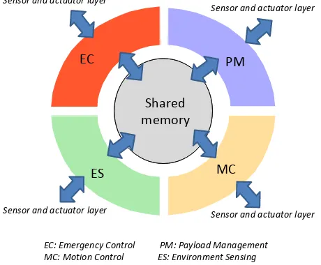
In order to achieve a better autonomy, we suggest to grandly update the currently used embedded architectures. Figure 1 presents the functional architecture that we currently develop (see also (Tanzi, 2014a)). It consists of four main subsystems: (1) the environment sensing (ES) subsystem (including obstacles and objectives) including the management of core platform sensors, (2) the motion control (MC) subsystem (navigation, planning, engine management, etc.), (3) the payload management (PM) and operation subsystem (the sensors needed for the mission) and (4) the emergency control (EC) subsystem, which detects flight issues (energy limitations, failures, or imminent crash) and decides to react (immediate landing, a parachute drop, an immediate come back to the base, etc.). The platform can also be remotely controlled through radio in semi-autonomous modes if commands are issued, or to transmit data from the payload or telemetry system (especially in the case of first-person video / FPV flight). Each subsystem can exhibit more or less autonomy. The main addition we suggest is the interconnection of those subsystems through a shared memory, or more specifically a blackboard system (see Section 3.1).
Sensor and actuator layer Sensor and actuator layer
PM: Payload Management ES: Environment Sensing
Figure 1: Functional view of the subsystems
2.2 Autonomy and dependability
Autonomy also acutely raises the problem of the dependability of the system, which can represent a danger to its environment. The architecture must indeed react to both accidental and platform-related mistakes (defective components, software errors, uncontrolled events), or to environment variations (weather, obstacles, quality of communication channel, etc.). These events can be accidental or even intentional (attacks).
In particular, the execution of tasks is based on a strict adherence to real-time deadlines. Tasks can be classified in terms of priority levels depending notably on the associated risk. For instance, low-level reactive features, which are typically emergency-related for the EC or MC subsystems, should have the highest priority. Monitors or observers may also be implemented to ensure that the interactions between the components of the drone are healthy and to filter undesirable interactions. From this standpoint, autonomy may mean energy management as well as autonomous decisions, depending on the subsystem considered.
MC
Engines Control Payload and Perception Sensors Mission Planning
Figure 2: Main component architecture
Figure 2 shows the architecture that we are currently developing from a component-oriented point of view. Components are monitored and triggered by the four subsystem controllers, depending on their respective role. The payload manager (PM) and the environment sensing subsystem (ES) are both in charge of different sensors and actuators respectively for the mission and for the situational awareness of the platform, and operate in parallel under the same circumstances. They sometimes have to rely on each other’s sensed data to improve their own operation. The motion controller (MC) interacts with several components like the avionics sensors or the engines, which it controls through autonomous decisions under normal flight conditions. Similarly, the motion controller may interact with components in the PM subsystem to improve their usage (see Section 4.2 for an example). The emergency controller (EC) can trigger yet other components like the parachute if the UAV goes out of its flight envelope. For example, abrupt changes in environmental conditions, a partial loss of flying capabilities, or a significant decrease in the battery level may require aborting the mission and returning to the base, or even activating the emergency parachute for an immediate landing.
Table 1 presents three levels of actions available for the EC subsystem, each corresponding to a different risk level.
Level Action Causes
1 Reduce the mission Resources are not sufficient 2 Abort mission Energy too low
3 Emergency stop System shutdown
Table 1: available actions at EC
requirements for obtaining relevant information (minimum sampling frequency, data that must be fused from different sensors, subsystems involved, etc.). Second, one must ensure that data sensing and processing is not going to interfere with the real-time operation of the system, especially for safety critical functions typically implemented by the MC and ES subsystems, for example by creating additional latencies or congestions.
3. ARCHITECTURAL SUPPORT
The following sections describe techniques to implement a core collaborative behavior to organize the interactions between subsystems and to modify this behavior to support specific events during the operation of the UAV.
3.1 Data sharing
Communications and collaboration between subsystems are central issues in the architecture that we propose. They change the architecture from a static one dedicated to a specific payload or task to a much more modular system in which every sensing subsystem formats and stores the data it acquires for other subsystems to use as they see fit.
We rely on a shared memory to manage the storage of and access to information collected by the sensors. The four basic subsystems will thus implement a multi-agent collaboration in a centralized manner, realized through systems well known in robotics as blackboards (Hayes-Roth. B., 1985) (Corkill. D. D., 1991) or whiteboards (Boitet, C. and Scligman, M., 1994) (Thórisson K. R., et al., 2005). Agents are the different functions that may interact. Sensors from the different subsystems play the role of knowledge sources, either in raw form, for the least verbose, or through some preprocessing that extracts a summarized dataset to be exchanged with other agents. Such a data structure based approach has proven quite useful in order to exchange data flexibly between processes without hardcoding specific data exchange patterns at code level, and without knowing in advance the interested recipients. It is quite important to retain a modular definition of subsystems, and even functions. Whiteboards are an extension of blackboards, supporting less structured data. Some of these even add, among other functionalities, messaging capabilities through the introduction of a communication middleware. Such mechanisms would be especially interesting for a UAV comprising distributed processors, like for instance multiple boards communication through buses.
Black/Whiteboards for instance would allow to access flight data (MC or ES) and payload sensor data (PM) from other subsystems and for instance to fuse them in order to improve the geolocation precision. The ever-increasing flight capabilities of UAVs coupled with the need to use of non-conventional sensors such as Lidars, GPRs, or IR cameras to improve the autonomy of UAVs will strongly increase the need for such data fusion features.
3.2 Subsystem organization and communications
In contrast with usual black/whiteboard systems in which processes are essentially independent, we claim that it is essential to handle priorities in an autonomous drone. Those priorities are themselves dictated by the nature of the data acquired, and then accessed. The definition of priorities directly depends on the specific mission undertaken.
The architecture typically aims at supporting the deployment of different data handling and processing strategies depending on the capabilities of the platform. For instance, if the processing power available onboard is not sufficient, communicating with external computing resources may be necessary in order to comply with the mission requirements. More generally, the architecture should make it possible to adapt to cost, environmental, and energetic constraints.
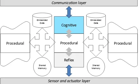
We suggest supporting priorities based on an event handling strategy and on three levels of operation. Each subsystem executes functions classified at three different levels (see Figure 3). The lowest-level or reflex mode of operation is intended to ensure a reactive response to events such as, for example, the correction of trajectory disturbed by an external event (e.g., unexpected wind). This first level of reaction relies on sensors and actuators directly accessible by the subsystem and is thus very fast. It may also benefit from techniques of firmware and hardware acceleration. Most events should be dealt with at that layer in normal modes of operation.
If that reaction is not sufficient, e.g., the deviation from the expected and programmed behaviour continues, the control should be passed to the procedural mode. A more complete pre-programmed analysis is then used that may notably access data from sensors in other subsystems. Communication with other subsystems may also be required as part of the reaction. For example, the emergency controller (EC) may notify the payload manager (PM) to terminate data acquisitions to adapt the overall system resources and behavior to a more demanding situation. This level of response is more complex with respect to communications and process synchronization, and may use more time to deal with a potential problem.
The last level, called the cognitive mode, is used whenever the previous mode couldn’t resolve the problem. It implements a deliberative analysis of the event that led to this mode and which can be an issue. It may even require communicating with a command centre and/or a human operator. The overall process is thus expected to be longer.
Cognitive
Figure 3: Multi-level subsystem organization and subsystem communication
reallocations, and may for instance require the preemption or suspension of existing activities.
3.3 Runtime mechanisms
We are currently implementing such mechanisms on top of a multicore architecture through thread synchronization. Threads provide a lightweight concurrency primitive with an API for the manipulation, preemption, or prioritization of multiple activities, which is exactly the functionality required to coordinate functions executing in our subsystems. Threads also come with synchronization primitives that we use to implement the black/whiteboard scheduler in our implementation and that solve the consistency problems incurred by parallel data accesses.
Furthermore, multicore systems are now available in an embedded form factor, like the Raspberry Pi 2, or even massively multicore one, like for instance the Parallela boards (up to 64 cores). The availability of such boards also shows that this technology becomes even very affordable for small drones. More specifically, with a multicore architecture, we can organize threads so that those with a similar priority may run in parallel on separate core. We can also take advantage of the parallelism inherent to multicore architectures to use threads on separate cores to implement majority voting schemes. In this manner, safety-critical data processing may be rendered more immune to an occasional glitch and thus achieve a more dependable behavior of the platform. Massively multicore platforms also seem quite appropriate for supporting costly computations incurred by image processing or complex data reconstructions and if so, would allow to process payload data on-board and during the flight.
Even though our current implementation efforts do not aim at implementing a real-time operating system, the platform would benefit from such mechanisms. We especially think of a microkernel like S4 that would allow virtualizing low priority tasks.
3.4 Dynamic resources adaptation : an example
To illustrate the operating principle of our adaptive mechanism, we take the example of a simplistic drone attitude control mechanism. That scenario unfolds during a Search And Rescue (SAR) mission. This mission consists in taking high-resolution photographs to create a mosaic of an area of interest (see table 2 and fig 4).
To simplify, we retain two types of constraints. The firsts relate to the completeness of the coverage of the research area and therefore the accuracy of navigation. The seconds are inherent to the quality of image acquisition – image overlap, image shake, etc. - and will be used when processing the mosaic.
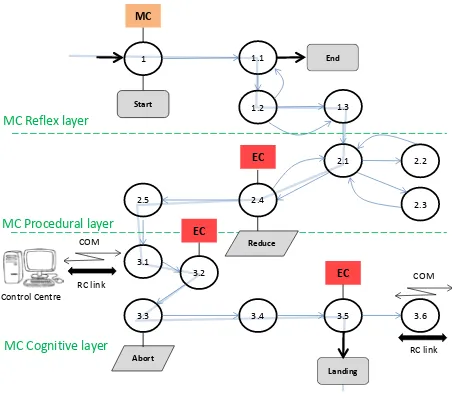
As depicted in the table and in the diagram, the arrival of events triggers adaptations and the execution of new processes within and among several subsystems due to changes in the mode of operation and due to the need to access specific data.
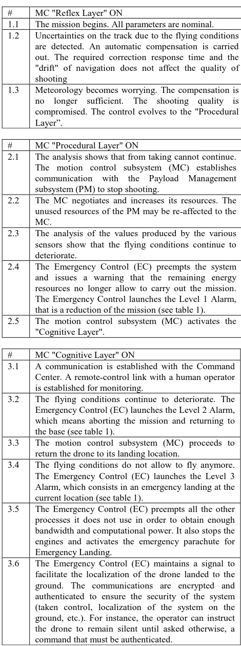
# MC "Reflex Layer" ON
1.1 The mission begins. All parameters are nominal. 1.2 Uncertainties on the track due to the flying conditions
are detected. An automatic compensation is carried out. The required correction response time and the "drift" of navigation does not affect the quality of shooting
1.3 Meteorology becomes worrying. The compensation is no longer sufficient. The shooting quality is compromised. The control evolves to the "Procedural Layer”.
# MC "Procedural Layer" ON
2.1 The analysis shows that from taking cannot continue. The motion control subsystem (MC) establishes communication with the Payload Management subsystem (PM) to stop shooting.
2.2 The MC negotiates and increases its resources. The unused resources of the PM may be re-affected to the MC.
2.3 The analysis of the values produced by the various sensors show that the flying conditions continue to deteriorate.
2.4 The Emergency Control (EC) preempts the system and issues a warning that the remaining energy resources no longer allow to carry out the mission. The Emergency Control launches the Level 1 Alarm, that is a reduction of the mission (see table 1). 2.5 The motion control subsystem (MC) activates the
"Cognitive Layer".
# MC "Cognitive Layer" ON
3.1 A communication is established with the Command Center. A remote-control link with a human operator is established for monitoring.
3.2 The flying conditions continue to deteriorate. The Emergency Control (EC) launches the Level 2 Alarm, which means aborting the mission and returning to the base (see table 1).
3.3 The motion control subsystem (MC) proceeds to return the drone to its landing location.
3.4 The flying conditions do not allow to fly anymore. The Emergency Control (EC) launches the Level 3 Alarm, which consists in an emergency landing at the current location (see table 1).
3.5 The Emergency Control (EC) preempts all the other processes it does not use in order to obtain enough bandwidth and computational power. It also stops the engines and activates the emergency parachute for Emergency Landing.
3.6 The Emergency Control (EC) maintains a signal to facilitate the localization of the drone landed to the ground. The communications are encrypted and authenticated to ensure the security of the system (taken control, localization of the system on the ground, etc.). For instance, the operator can instruct the drone to remain silent until asked otherwise, a command that must be authenticated.
MC
1 1.1
1.2 1.3
2.1 2.2
2.3
3.1 3.2
3.3
EC
3.5
3.4 3.6
Abort Start
End
Landing COM
RC link MC Reflex layer
MC Procedural layer
MC Cognitive layer
EC EC
2.4 2.5
Reduce
COM
RC link Control Centre
Figure 4: Operation modes and resource adaptation
4. DESIGN AND VALIDATION METHODOLOGY
The approach we suggest relies on the adaptation of a core platform and its sensors and actuators to specific payloads and missions. The specific mission constraints typically dictate the behavior that the autonomous UAV embedded system must follow during data acquisition, as well as the risks it will have to face in its environment. The large number of software and hardware components that must be integrated in the architecture and their numerous configurations makes it necessary to use validation approaches. These tools will be used in all design and development phases in order to ensure the satisfaction of safety properties, which are essential for the performance (processor optimization, function placement), safety (realtime execution of safety critical tasks) as well as for the data acquisition quality. In many situations, security properties must also be assessed, which address attacks aimed at the platform, at its communication links, or at the data acquired.
4.1 Modelling and validation environment
We experimented in the past with validation issues on dependable communicating embedded automotive architectures
(Schweppe, 2011) and autonomous drones. This work has relied on our modelling system, which is based on a UML software/hardware partitioning environment named DIPLODOCUS (Apvrille, 2006) / TTool (see http://ttool.telecom-paristech.fr). DIPLODOCUS is based on the UML language and includes the "Y" scheme (Balarin, 2003).
The approach consists in a three-step methodology: (i) model the functions of the system, (ii) capture the candidate hardware architectures, which is defined in terms of processors, buses and memories, and finally (iii) allocate functions and their communications to the resources of the hardware architecture and study the impact of this allocation with respect to the properties assessed.
In the first iterations of the design, the main purpose of validation is not so much to search for possible deadlock situations usually studied on more accurate models than to study the load of processors and platform buses, and the impact of this load on the flight capabilities of the drone. TTool offers a press-button approach to verify the models by simulation or formal verification. The results of these verifications can be displayed directly on the models (see Figure 6).
4.2 An example: a small drone
We now illustrate some results obtained out of the modelling and validation methodology for a mini-drone aimed at autonomously navigating inside buildings developed in the drone4u project (see https://drone4u.telecom-paristech.fr). This drone was implemented on top of an existing drone platform (Ranft, 2013). The drone uses a front 720p monocular camera to capture 2D images. The realization of a “corkscrew flight” allows to reconstruct the UAV 3D environment from a stereoscopic reconstruction out of pairs of 2D images taken during this movement. This requires the synchronization between the motion control (MC) subsystem and the payload management (PM) in charge of image acquisition. The UAV deduces from its environment model flight orders that are sent to the flight control agent. This system relies on a combined on-board handling and pre-processing of sensor data and offline data interpretation in a separate computer wirelessly connected to the drone.
Figure 5 depicts the logical functional architecture that is the different functions that must later on be mapped onto processors, and how they communicate. This diagram makes it possible to enumerate all potential interactions that may place some load on buses or more generally communication links. For instance, one can clearly see that data from the different sensors (video, attitude, altitude) are sent separately to the ComputingNavigationOrders function that fuses them to interpret the scene before sending commands to the FlightControl. This diagram depicts both events and data flows with separate colors. However, our tool cannot yet handle dynamic resource reassignments and priorities as discussed in this paper.
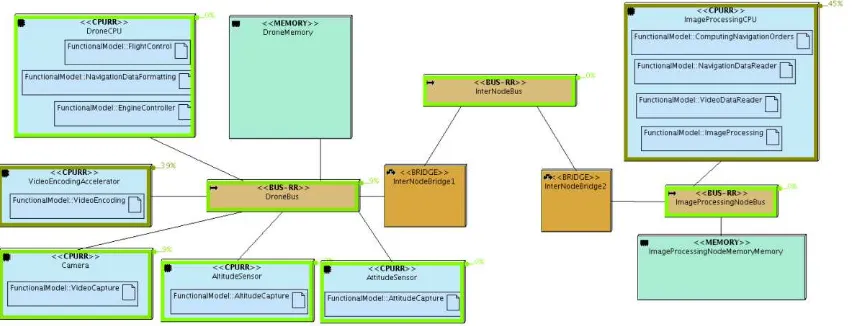
Figure 6 displays the function placement with respect to CPUs. Multiple functions can be mapped to the same processor.
This diagram also depicts the platform load computed for a drone handling 720p images. This overview is obtained from TTool that computes the CPU load resulting from a simulation of the different tasks at hand, as well as a simulation of the inter-CPU information flows triggered by function interactions. One can notice that the external CPU, where the image processing functions are placed, is quite loaded, whereas the rest of the platform is only lightly loaded. This can be used to determine that it would be quite safe to run the emergency tasks on the drone CPU for instance. Other simulations about emergency situations have also been successfully performed to verify that this partitioning of functional tasks can support emergency response functions within acceptable realtime constraints.
Figure 6: Placement of functions and load analysis for the drone platform
5. CONCLUSIONS AND FUTURE WORK
Designing drones that may perform complex missions is already an important challenge [Marks, 2013], yet UAVs will likely become mainstream only if their manipulation does not require special skills. The realization of an autonomous UAV in this context is even more demanding, especially in terms of architectures able to support this autonomy with a very good level of safety and efficiency. The choice of the runtime platform is extremely important to meet these needs. Our platform proposal relies on the use of multicore platforms together with modes of execution that capture emergency situations. It also relies on the separation between competing functions in terms of priorities, and on real-time resource adaptations at platform level.
The use of modelling and verification tools is an important improvement to handle the system complexity and more importantly improves the confidence with regards to the performance, safety, and security properties met by the platform under real conditions of operation. We proposed an approach relying on the definition of the hardware and software components and their partitioning. In this paper, we illustrated this approach with the example of an autonomous drone system that we implemented. We presented early modeling and verification results based on real-time constraints and a simple function partitioning of the drone system modeled using our modeling environment TTool.
We are currently refining our architecture and validation approach to develop autonomous drones in the scope of post-disaster humanitarian relief operations (Tanzi, 2014b). The use of advanced sensors that will be necessary in such situations will require a significant effort to define the coordination patterns among the different subsystems constituting the UAV platform. We will investigate ways to express these in a simple manner.
REFERENCES
Ackerman, E., 2013. Drone Adventures Uses UAVs to Help Make the World a Better Place. IEEE Spectrum: Technology, Engineering, and Science News, May 2013.
Apvrille, L., et al, 2006. A UML-based Environment for System Design Space Exploration. 13th IEEE International Conference on Electronics, Circuits and Systems (ICECS'2006), Nice, France, December 2006
Balarin, et al, 2003. Metropolis: An Integrated Electronic System Design Environment. Computer, 36(4):45–52.2003.
Boitet, C. and Scligman, M., 1994. The "Whiteboard" Architecture: A Way to Integrate Heterogeneous Components of Nlp Systems. In Proceedings of the 15th conference on Computational linguistics, Volume 1. Pages 426-430. 1994.
Guha-Sapir, D., Hoyois, P. and Below, R., 2013 “Annual Disaster Statistical Review 2012: The Number and Trends,” in CRED, Brussels, Belgium, 2013.
Hayes-Roth, B., 1985. A Blackboard Architecture for Control. Artificial Intelligence 26. Pages 251-321. 1985
Lefeuvre, F. and Tanzi, T.J, 2013. “International Union of Radio Science, International Council for Science (ICSU), Joint Board of Geospatial Information Societies (jBGIS),” in United Nations office for outer Space Affairs (OOSA), 2013.
Marks, P, 2013. “Smart Software Uses Drones to Plot Disaster Relief,” NewScientist, Nov. 2013.
Ranft, B., et al, 2013. "3D Perception for Autonomous Navigation of a Low-Cost MAV using Minimal Landmarks", Proceedings of the International Micro Air Vehicle Conference and Flight Competition (IMAV'2013), Toulouse, France, 17-20 Sept. 2013.
Schweppe, H., et al, 2011. C2X Communication: Securing the Last Meter. Proceedings of the 4th IEEE International Symposium on Wireless Vehicular Communications: WIVEC2011, San Francisco, United States, 5-6 September 2011.
Tanzi, T.J. and Lefeuvre, F, 2011. “The Contribution of Radio Sciences to Disaster Management,” in International Symposium on Geo-information for disaster management (Gi4DM 2011), Antalya, Turkey, 2011.
Tanzi, T. J., et al, 2014a. UAVs for Humanitarian Missions: Autonomy and Reliability. IEEE Global Humanitarian Technology Conference (GHTC), San José, California USA, October 10-13, 2014.
Tanzi, T. J., Isnard, J., 2014b. Robot d’intervention multifonction d’assistance post-catastrophe. Réflexions sur un drone "humanitaire". Revue de l’Electricité et de l’Electronique (REE), 3/2014. pp 24-30.
Thórisson K. R., et al., 2005. Whiteboards: Scheduling Blackboards for Semantic Routing of Messages & Streams. AAAI-05 Workshop on Modular Construction of Human-Like Intelligence, Twentieth Annual Conference on Artificial Intelligence, Pittsburgh, PA, July 9-13, 2005