[2] M. Overmars and P. Svestka, “A probabilistic learning approach to motion planning,” inProc. Algorithmic Found. Robot., 1995, pp. 19–37. [3] Y. Koga and J.-C. Latombe, “On multi-arm manipulation planning,” in
Proc. IEEE Int. Conf. Robot. Autom., May 1994, vol. 2, pp. 945–952. [4] G. Sanchez and J.-C. Latombe, “On delaying collision checking in PRM
planning: Application to multi-robot coordination,”Int. J. Robot. Res., vol. 21, pp. 5–26, 2002.
[5] G. Sanchez and J.-C. Latombe, “Using a PRM planner to compare cen-tralized and decoupled planning for multi robot systems,” inProc. IEEE Int. Conf. Robot. Autom., 2002, vol. 2, pp. 2112–2119.
[6] C. M. Clark, S. M. Rock, and J.-C. Latombe, “Dynamic networks for motion planning in multi-robot space systems,” inProc. Int. Symp. Artif. Intell. Robot. Autom. Space, 2003, pp. 3621–3631.
[7] S. Karaman and E. Frazzoli, “Incremental sampling-based algorithms for optimal motion planning,” inProc. Robot. Sci. Syst., May 2010. [8] M. Otte and N. Correll, “Any-com multi-robot path-planning:
Maximiz-ing collaboration for variable bandwidth,” inProc. Int. Symp. Distrib. Autonom. Robot. Syst., 2010.
[9] S. M. LaValle and J. J. Kuffner, “Rapidly-exploring random trees: Progress and prospects,” inProc. Algorithm Comput. Robot. Direct., 2001, pp. 293–308.
[10] S. Caselli and M. Reggiani, “Randomized motion planning on parallel and distributed architectures,” inProc. Euromicro Workshop Parallel Distrib. Process., 1999, pp. 297–304.
[11] N. M. Amato and L. K. Dale, “Probabilistic roadmap methods are embar-rassingly parallel,” inProc. IEEE Int. Conf. Robot. Autom., 1999, vol. 1, pp. 688–694.
[12] J. Ichnowski and R. Alterovitz, “Parallel sampling-based motion planning with superlinear speedup,” inProc. IEEE/RSJ Int. Conf. Intell. Robot. Syst., Oct. 2012, pp. 1206–1212.
[13] J. Bialkowski, S. Karaman, and E. Frazzoli, “Massively parallelizing the RRT and the RRT,” inProc. IEEE/RSJ Int. Conf. Intell. Robot. Syst., Sep. 2011, pp. 3513–3518.
[14] I. A. Sucan and L. E. Kavraki, “Kinodynamic motion planning by interior-exterior cell exploration,” inProc. 8th Worksh. Algo. Found. Robot., 2009, pp. 449–464.
[15] D. J. Challou, M. Gini, and V. Kumar, “Parallel search algorithms for robot motion planning,” inProc. IEEE Int. Conf. Robot. Autom., May 1993, vol. 2, pp. 46–51.
[16] E. Plaku, K. E. Bekris, B. Y. Chen, A. M. Ladd, and L. E. Kavraki, “Sampling-based roadmap of trees for parallel motion planning,”IEEE Trans. Robot., vol. 21, no. 4, pp. 587–608, Aug. 2005.
[17] M. Otte and N. Correll, “Any-com multi-robot path-planning with dy-namic teams: Multi-robot coordination under communication constraints,” inProc. Int. Symp. Exper. Robot., 2010.
[18] T.-Y. Li and Y.-C. Shie, “An incremental learning approach to motion planning with roadmap management,” inProc. IEEE Int. Conf. Robot. Autom., 2002, vol. 4, pp. 3411–3416.
[19] R. Gayle, K. R. Klingler, and P. G. Xavier, “Lazy reconfiguration forest (LRF)— An approach for motion planning with multiple tasks in dy-namic environments,” inProc. IEEE Int. Conf. Robot. Autom., Apr. 2007, pp. 1316–1323.
[20] M. Zucker, J. J. Kuffner, and M. S. Branicky, “Multipartite RRTs for rapid replanning in dynamic environments,” inProc. Int. Conf. Robot. Autom., 2007, pp. 1603–1609.
[21] D. Ferguson and A. Stentz, “Anytime RRTs,” inProc. IEEE/RSJ Int. Conf. Intell. Robot. Syst., Oct. 2006, pp. 5369–5375.
[22] N. A. Wedge and M. S. Branicky, “On heavy-tailed runtimes and restarts in rapidly-exploring random trees,” inProc. AAAI Conf. Artif. Intell., 2008.
[23] M. Luby, A. Sinclair, and D. Zuckerman, “Speedup of Las Vegas algo-rithms,” inProc. 2nd Israel Symp. Theor. Comput. Syst., 1993, pp. 128– 133.
[24] B. Yamrom, “Alpha puzzle,” Provided by GE Corporate Research and Development Center, via Parasol Lab at Texas A & M University, [Online]. Available: http://parasol.tamu.edu/dsmft/benchmarks/mp/
[25] J. J. Kuffner, “Effective sampling and distance metrics for 3D rigid body path planning,” inProc. IEEE Conf. Robot. Automat., Apr./May 2004, vol. 4, pp. 3993–3998.
3-D Localization of Human Based on an Inertial Capture System
Qilong Yuan and I.-Ming Chen, Fellow, IEEE
Abstract—This paper introduces a method to track the spatial location
and movement of a human using wearable inertia sensors without addi-tional external global positioning devices. Starting from the lower limb kinematics of a human, the method uses multiple wearable inertia sensors to determine the orientation of the body segments and lower limb joint motions. At the same time, based on human kinematics and locomotion phase detection, the spatial position and the trajectory of a reference point on the body can be determined. An experimental study has shown that the position error can be controlled within 1–2% of the total distance in both indoor and outdoor environments. The system is capable of localization on irregular terrains (like uphill/downhill). From the localization results, the ground shape and the height information that can be recovered after local-ization experiments are conducted. A benchmark study on the accuracy of this method was carried out using the camera-based motion analysis system to study the validity of the system. The localization data that are obtained from the proposed method match well with those from the commercial system. Since the sensors can be worn on the human at any time and any place, this method has no restriction to indoor and outdoor applications.
Index Terms—Human performance augmentation, humanoid robots,
personal localization.
I. INTRODUCTION
Tracking the location and behavior of a human for many indoor and outdoor applications has been a very important problem and chal-lenging issue. For outdoor applications, the global positioning sys-tem (GPS) is a much mature technology that can provide the spatial location of the subject. However, for accurate human tracking with 3-D locations which requires the precise location information, there are still many technology hurdles to overcome due to the complexity of the environments. The main uses for indoor/outdoor human tracking are in medicine, healthcare, business logistics, manufacturing, com-mercial advertisement, and possibly entertainment. People may want to know the whereabouts of a particular subject or a group of subjects for a certain time period or to continuously monitor the activities of the subject for detail analysis.
In this paper, we introduce a new method to track the spatial lo-cation of a human in daily living environments. In these applilo-cation scenarios where the activities can be conducted within large volume and various terrains, the use of sensing fixtures, such as camera, in-frared light [1], ultrawideband (UWB) [2], radio-frequency identifica-tion (RFID) tags [3], ultrasonic, etc., [4], [5] should be avoided in order to keep the system cost manageable. For example, it is not practical to set up and calibrate the camera-based systems within the stairway to capture persons’ climbing stair behavior. Therefore, in daily prac-tical applications, a self-contained wearable suit that can accurately track the location and behavior of the subjects in indoor and outdoor environments is expected.
Manuscript received September 18, 2012; revised January 16, 2013; accepted February 6, 2013. Date of publication March 11, 2013; date of current version June 3, 2013. This paper was recommended for publication by Associate Edi-tor R. Eustice and EdiEdi-tor D. Fox upon evaluation of the reviewers’ comments. This work was supported in part by the Agency for Science, Technology, and Research, Singapore, under SERC Grant 092 149 0082.
The authors are with the School of Mechanical and Aerospace Engineer-ing, Nanyang Technological University, Nanyang 597627, Singapore (e-mail: [email protected]).
Color versions of one or more of the figures in this paper are available online at http://ieeexplore.ieee.org.
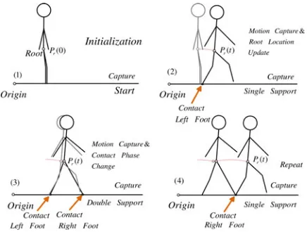
Fig. 1. Working principle of the method.
Recently, several inertial-based self-contained human localization systems have been proposed [3], [5]–[9]. Among them, the zero velocity updates (ZUPTs) method that was proposed by Foxlin can work nicely for regular walking localization [10], [11]. A Nav-shoe with shoe-mounted inertial sensors is used to track the location of the emergency responders. This method only tracks the foot location, and the foot stance phase is required for localization.
Another inertial-based personal dead reckoning method roughly es-timates the walking speed and distance based on the pattern of walking accelerations [12]. This method is 2-D localization with moderate accu-racy, and it is also quite user dependent. Woodman and Harle propose a 2.5-D indoor user location tracking method that is based on envi-ronmental constraints [13]. This method needs the predefined maps of the environment. As existing shoe-mounted tracking devices only have coarse location information, it is insufficient to fully understand the posture behavior of a subject most of the time.
The recent inertial simultaneous localization and mapping (SLAM) technology [14]–[16] that is based on camera and inertial sensors is capable of tracking the spatial motion of object, which is proper for automobile and aircraft localization. For human spatial localization and capture, the extra cameras will increase the cost and the complexity of the whole system and make the computation too complex for real-time spatial human motion tracking. Another critical issue is that when oc-clusion happens, the camera cannot work. Because of the same reason, other camera-based localization techniques (computer vision [12] and visual SLAM [16]–[18]) are also not applied in this study.
Humanoid robots (QRIO, Asimo, etc.) have encoders in their joints and the change in position can be estimated using the forward kinemat-ics. Inspired by this, this method is proposed to track the 3-D position. It is known that walking requires human feet in contact with the ground. Thus, by identifying the contact state of the human feet on the ground and capturing the lower limb postures and movements continuously at the same time, one should be able to know the trajectory of a refer-ence point on the human body over a period of time. Because the body postures and movements contain 3-D data, the localization results are the 3-D position of the subject. The method is illustrated in Fig. 1. Ini-tially (1), the system registers the global positionPr(0) of a reference point on the human body (root) from some fixed global coordinate, and also calibrates the body posture. When the subject starts to move and walk (2), the sensors begin to capture lower limb postures and compute the trajectory of the root point. As the human continues to walk, the foot contact patterns are captured and identified by the foot sensors (3). Together with continuous motion capture, the kinematic
is outside the scope of this paper. Some of our works about dynamic behavior localization are now presented in [19] and [20].
This paper is an extension of the one presented in ICRA 2011 [21] with additional contents in calibration method and experimental re-sults. The remaining parts of this paper are organized as follows. Section II discusses the methodology. Section III discusses the sys-tem calibration. Section IV introduces the proposed syssys-tem devices. In Section V, the experimental results are provided in detail. Finally, Section VI concludes this paper.
II. METHODOLOGY
The localization and capture of the subject consist of two major issues: body joint motion capture and localization of the body. The joint motions can be captured properly from these accurate orienta-tion estimaorienta-tions of IMU sensors. With well-calibrated skeleton models and reliable contact event detection results, the root location can be accurately updated based on the kinematics of lower limbs.
A. Joint Motion Tracking
The joint motion is the relative orientation of the two adjacent seg-ment body frames that are represented by a rotation matrix. As a result, the joint motions can be derived from the IMUs’ outputs. Taking the waist joint motion calculation as an example, the methodology is pro-vided in (1) following Fig. 2:
RU0 1=RT0RU1 (1)
whereR0 andRU1 are the rotation matrices that represent the orien-tation of pelvis and upper body frame with respect to the global frame (“U1” and “0” denote the upper body and the pelvis, respectively). They are updated from the IMU orientation after a corresponding mapping is applied
R0 =R0SRT0M, RU 1=RU1SRTU1M (2)
whereR0S andRU1S are updated from the IMU outputs.R0M and
RU1M are the coordinate mappings that are discussed in Section III. They are considered as constant matrices after the sensors are fixed onto the body, until a recalibration is carried out.
B. Continuous Root Location Update
To localize the subject in the surroundings, the 3-D trajectory of the root point and joint motions of the subject need to be continuously tracked. Initially, the location and postures of both feet and the root are calibrated. In each capturing cycle, shoe pads detect which foot is in contact with the ground. From the location of this supporting foot, the root location and the swinging foot location can be calculated using the body joint motions and 3-D limb dimensions of the subject.
Fig. 2. Mappings for joint motion computations.
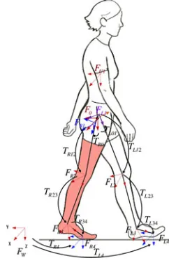
Fig. 3. Definitions of coordinate frames.
as shown in Fig. 6. The dimensions from the ankle to the sensors and the heel are estimated and used to calculate the stride lengths. The locations of the FSR sensors are always updated in real time so that the root location can be updated accordingly. Thus, this method is available for human walking with various walking pattern or other gaits such as dancing, Tai-Chi, etc.
2) Root Location Update: After the contact condition is determined in each sampling cycle, the root location can be updated from the de-tected supporting foot. The root location is calculated from the sup-porting foot. If both feet are in contact phase, both feet locations can contribute to update the root location.
This way, the trajectories of the root as well as two feet are always updated in every cycle. In cases where the ground truth is available, the foot height can be corrected during the localization. Therefore, the location of the supporting foot is available whenever it is requested for root location update.
Updating the root location from supporting foot through the kine-matic chain of lower limbs is a forward kinekine-matics problem once the joint motions and the skeleton dimensions of the subject are determined, as shown in Fig. 3.
When the right foot is detected as the foot in contact with the ground, the right foot remains in the same location, and the root location and the left foot locations are calculated based on the right foot. The
dis-Fig. 4. Procedure for sensor mapping calibration.
placement of the root and the left foot is represented as follows:
T0 =TR4T
T R3 4T
T R2 3T
T R1 2T
T
R0 1 (3)
TL4 =T0TL0 1TL1 2TL2 3TL3 4. (4)
Similarly, when the left foot is in the support phase in contact with the ground, the root location is calculated which is based on the left foot
T0 =TL4T
T L3 4T
T L2 3T
T L1 2T
T
L0 1 (5)
TR4 =T0TR0 1TR1 2TR2 3TR3 4. (6)
The definitions of the notations are shown in Fig. 3; details are dis-cussed in [21]. Note that the stride error distribution can be analyzed which is based on the probability distribution of the kinematic parame-ters. Thus, the position uncertainty can be updated accordingly in order to fuse with external positioning devices. This will be presented in the future work.
III. CALIBRATION OF ASYSTEM
Calibration is a necessary procedure to optimize the system parame-ters for precise localization. It has been stated that the localization and capture techniques depend on the sensor orientation outputs and the skeleton models of the subjects. To make the system work properly, the coordinate mappings from sensor frames to the corresponding body segment frames and the lower limbs dimension need to be determined to have a full representation of the kinematic chain for the root location update. Therefore, before motion tracking, a calibration procedure is needed to determine all these parameters for the initialization of the whole system.
A. Calibration of Coordinate Mapping
The sensor orientations in the corresponding body frames provide the mapping from sensor motion to body segment motions. A cali-bration is conducted to get these mappings before actual motion cap-ture. From the definition of body segment frame [21], it is known that in the initial standard posture, these frames are parallel with the right-handed body frame with theX-axis pointing forward and the
Z-axis pointing downward. The orientation of this body frame is known once the bearing of the subject is determined. Therefore, determining the body bearing becomes a key issue for the calibration of mappings in this inertial-based system.
Step 1:After attaching all the sensors on the corresponding body segments, the subject stands still in an initial standing posture. Then, keep the posture for 10 s during which the posture will be saved in the computer.
Step 2: Stoop down in the forward direction as shown in Fig. 4 and keep the posture for 10 s for the computer to save the stoop posture.
During the two steps, the upper body of the subject only rotates around theY-axis of his waist which is also theY-axis of the body frame, as presented in Fig. 4. Thus, we are able to identify this axis by extracting the rotation axis of the motion of the upper body. LetRs1and
Rs2 represent the rotation matrix of the upper body in the standstill posture and the stoop posture with respect to the global frameFW, respectively. The relative rotation matrix from the standstill posture to the stoop posture becomes
Rs1 2 =RTs1Rs2. (7)
For this relative rotation, the direction of a rotation axis in a global frame can be presented as follows:
rW
s1 2 =Rs1rsB1 2=Rs1Sc(Rs1 2) = (xs1 2, ys1 2, zs1 2). (8)
Here,Sc(Rs1 2)is a function that extracts the rotation axis of the rotation matrixRs1 2in the local body frame.
Referring to [21], the bearing of the body is calculated by
Φ =−arctan 2(xs1 2, ys1 2). (9)
Based on this bearing angle, the mapping between limbs and sensors can be determined. The details of this mapping calibration are shown in [21].
B. Skeleton Model Determination
For precise motion tracking, the measurement of the body sions of the human is very critical. Directly measuring the limb dimen-sion can provide a rough 2-D skeleton model. However, an accurate skeleton model can result in better localization results. Thus, a foot-print template-based skeleton calibration method is developed [22] (see Fig. 5). The 3-D limb dimensions can be optimized that are based on the footprint matching process. Basically, this method determines the 3-D limb length of the subject to best fit the sensor output with the pre-designed footprint locations. The dimensions of limbs can be solved based on the kinematic equations in these strides. After the calibration, the 3-D skeleton model and the stride error model [21] are determined. The localization results match nicely with the target footprints after this calibration. The entire calibration can be completed within only 2 min.
IV. SYSTEMDEVICES
For the actual capturing and identifying the foot contact phases while human moves, IMUs are used which can detect the spatial orientation of the object and other kinetic parameters such as angular velocity and accelerations. The human postures and movements can be captured
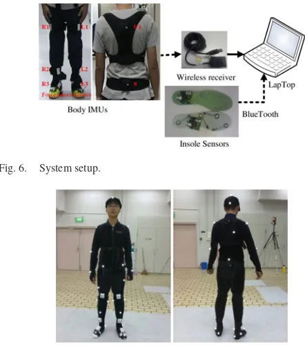
Fig. 6. System setup.
Fig. 7. IMU and MOCAP markers’ setup for comparison.
by using eight IMUs (K-Health, InterSense [23], [24]) worn on the body [25]–[27]. FSR contact sensors and the controller are fabricated and built into the shoe pads to identify the foot contacts.
As shown in Fig. 6, the system consists of eight wireless IMU sensors to be worn on the body (one on the trunk, one on the pelvis, and three for each leg attaching one on the thigh, the shank, and the foot, respectively) and the insole devices with force sensors to be worn under the feet. All sensors communicate wirelessly with the PC through Bluetooth and proprietary protocols (sampling rates: 100 Hz). Therefore, they have little constraint on the subjects’ motion.
V. EXPERIMENT ANDANALYSIS
In order to verify the capability of the proposed method, and study the accuracy of the system, experiments are conducted under different ground conditions.
First of all, in order to evaluate the validity of the proposed system, a benchmark study is conducted between the proposed system and the commercial optical motion capture system, i.e., Motion Analysis.
To test the system in 3-D localization and capture applications, the following terrain conditions are tested: 1) stair climbing; 2) in-door/outdoor mixture surrounding; and 3) the outdoor environments are also conducted on the uphill/ downhill terrain and the outdoor stairs.
A. Benchmark With Motion Analysis
Motion Analysis is used as the benchmark system to provide the ground-truth information during localization. The system that is used in our benchmark study consists of eight cameras. In this study, the subject wears the reflective markers and inertial system together, as shown in Fig. 7. The subject walks along the platform back and forth for four times at a speed of 0.8 m/s. The walking motion is captured by the two systems at the same time.
Fig. 8. Localization results of the two systems.
Fig. 9. Feet and CG trajectories for climbing up stairs.
root trajectories from the two systems are collected and compared after the trajectories are presented in the same global coordinate frame.
The two localization results along the walking direction are shown in Fig. 8 for comparison. The red line provides the ground-true reference from the optical system. The black line shows the result from the proposed method, and the blue line provides the errors with an RMS error of 0.20 m. It is shown in Fig. 8 that the error is large while turning around, and it increases gradually. Although drifting is inevitable for this stride-based method, the precise estimation significantly reduces the drifting rate in localization. For long distance traveling, assistive position information can be added.
B. Localization of Up and Down Stairs
In existing personal localization systems, the altitude of the subject cannot be accurately tracked if there are no ground-truth references. In order to show the capability of localization in the vertical direction, we conducted a stair climbing experiment to localize the subject. In this experiment, the subject first went up the standard 280 mm×180 mm stairs and then down to the original position.
The trajectory of the feet and the estimated center of gravity (CG) for climbing up stairs are shown in Fig. 9. The estimated CG is calculated from the captured postures with arm motion ignored. In this experiment, the absolute reference is not used in the proposed method. It is clear that the subject climbed one stair for each step.
C. Indoor/Outdoor Environment
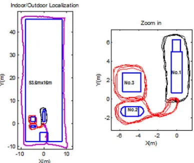
To show the capability of the system in a large-area scenario, an indoor/outdoor experiment is conducted. The subject first walks in the indoor environment around tables for several rounds (three rounds for table 1, and four rounds for tables 2 and 3). After that, he walks around the corridor of the room in an outdoor environment, and finally goes back to the starting point.
The trajectory of the root is shown in Fig. 10.The average closed-loop errors for each path are provided in Table I. In multiple-round
Fig. 10. Indoor/outdoor mixture localization. TABLE I
CLOSED-LOOPERRORS ININDOOR/OUTDOOREXPERIMENTS
Fig. 11. Localization results of all users.
localization around the tables (1, and 2 and 3) as shown in Fig. 10, the method is shown to be repeatable (for each round, the closed-loop errors around table 1 are always within (0.080 m, 0.066 m), and within (0.052 m, 0.072 m) for the path around tables 2 and 3). Overall, the error for one single round is around 1% of the total distance in these results. The even ground is used as constraints for the environments on the even terrains. Note that the orientation of the trajectory changes because of the heading errors from the magnetic disturbance near the indoor environment. More robust IMU algorithms to deal with this magnetic disturbance are reported in [26]. This will improve the heading accuracy in future work.
D. Tests on Different Persons
In order to test the system capability for the localization of different users and to study its repeatability, experiments of walking around an artificial pond (the total length for each round is about 90 m) are conducted by four users (height: 174.2±4.7 cm).
After the system calibration, each user walks around the outside of the pond for three times. The users stop at the starting position to form a closed loop every time.
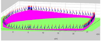
Fig. 13. Result for uphill/downhill terrain.
direction separately, with the standard deviation of (0.34 m, 0.71 m). The closed-loop error is about 1% of the total path length. Thus, the system is generally repeatable and robust on users with different body sizes.
E. Outdoor Irregular Terrains
1) Uphill/Downhill Terrain: In this proposed method, even though no ground reference is available, the 3-D localization of the subject in irregular terrains can also be properly captured based on the calibrated model.
A 3-D localization and capture experiment is conducted around a roundabout with irregular shapes as shown in Fig. 12, where the subject repeated this experiment for two times. The height of the ground varies around the outer profile. The subject walks around the profile starting from the top position for two rounds. The results including the location and the posture of the subject are shown in Fig. 13.
More importantly, based on the proposed systems, after a localiza-tion experiment is conducted around the areas of interest, the ground conditions can be recovered based on the captured results. In Fig. 13, the upper edge of the pink surfaces provides the detected ground sur-faces during the experiment.
Currently, because of the unknown dimension of the irregular terrain, which is very difficult to measure, the closed-loop error is used for localization accuracy evaluation. From the result, the total distance for each round is 98.6 m, and the closed-loop error for the two rounds is within 0.7 m along all directions. Error within 1% is achieved in an outdoor environment.
2) Outdoor Multiorientation Stairs: Based on this method, the ex-periments of climbing a multiorientation stair are also conducted as shown below.
The subject climbs up and down the stairs wearing the portable devices for three rounds. The localization results and the lower limb motions are presented in Fig. 15. The estimated path length is around 65 m. In the horizontal plane, the average closed-loop errors for the three rounds are−0.226 and−0.49 m in the north and east directions separately. In the vertical direction, the standard height per stair is used as a constraint. Thus, the drifting error in this direction is prevented. There is no stair missing in the tracking results. Besides, the spatial behaviors of the person during these motions are captured.
VI. CONCLUSION
In this paper, a new method for the 3-D localization of a human based on body kinematics and locomotion phase detection has been proposed. The complete system includes eight IMUs and one pair of sensitive shoe pads. Experimental results showed good accuracy in even-ground walking, stair climbing, and irregular terrains. Overall speaking, the accuracy of this system is within 1–2% of the total distance.
Compared with the existing localization techniques, this method does not depend on any external absolute positioning devices, and it is applicable for many moving patterns instead of only for normal walking. The system is robust for different users, and its repeatability is validated based on the experimental results.
Currently, the proposed method can handle motions with distinctive contact conditions. Research is underway for the localization of the human in fast movements with unstable contact states, such as fast walking, jogging, and jumping. Since the lab-based systems are not applicable in a large outdoor environment, this proposed new method and its further implementation [20] can be very useful for applications such as outdoor sports, daily exercises, and patient monitoring in house environments.
REFERENCES
[1] J. Hesch, F. Mirzaei, G. Mariottini, and S. Roumeliotis, “A Laser-Aided Inertial Navigation System (L-INS) for human localization in unknown indoor environments,” inProc. IEEE Int. Conf. Robot. Autom., 2010, pp. 5376–5382.
[2] J. Corrales, F. Candelas, and F. Torres, “Hybrid tracking of human op-erators using IMU/UWB data fusion by a Kalman filter,” inProc. 3rd ACM/IEEE Int. Conf. Human Robot Interact., 2008, pp. 193–200. [3] V. Renaudin, O. Yalak, P. Tom´e, and B. Merminod, “Indoor navigation of
emergency agents,”Eur. J. Navigat., vol. 5, pp. 36–45, 2007.
[4] C. Fischer, K. Muthukrishnan, M. Hazas, and H. Gellersen, “Ultrasound-aided pedestrian dead reckoning for indoor navigation,” inProc. 1st ACM Int. Workshop Mobile Entity Localization Track. GPS-Less Environ., 2008, pp. 31–36.
[5] J. Torres-Solis, T. Falk, and T. Chau, “A review of indoor localization technologies: Towards navigational assistance for topographical disorien-tation,”Ambient Intell., pp. 51–84, 2009.
[6] L. Ojeda and J. Borenstein, “Non-GPS navigation with the personal dead-reckoning system,”Unmanned Syst. Technol. IX, vol. 1, pp. 6561–6571, 2007.
[7] L. Ojeda and J. Borenstein, “Non-GPS navigation for emergency respon-ders,” inProc. 1st Joint Emergency Preparedness Response/Robot. Remote Syst. Topical Meet., 2006, pp. 356–363.
[8] O. Bebek, M. Suster, S. Rajgopal, M. Fu, X. Huang, M. Cavusoglu, D. Young, M. Mehregany, A. van den Bogert, and C. Mastrangelo, “Per-sonal navigation via shoe mounted inertial measurement units,” inProc. IEEE/RSJ Int. Conf. Intell. Robots Syst., 2010, pp. 1052–1058. [9] G. Retscher, “An intelligent multi-sensor system for pedestrian
naviga-tion,”J. Global Position Syst., vol. 5, pp. 110–118, 2006.
[10] E. Foxlin, “Pedestrian tracking with shoe-mounted inertial sensors,”IEEE Comput. Graph. Appl., vol. 25, no. 6, pp. 38–46, Nov./Dec. 2005. [11] A. Peruzzi, U. Della Croce, and A. Cereatti, “Estimation of stride length
[12] M. Kourogi and T. Kurata, “Personal positioning based on walking loco-motion analysis with self-contained sensors and a wearable camera,” in Proc. 2nd IEEE/ACM Int. Symp. Mixed Augment. Reality, Washington, DC, USA, 2003, pp. 103–112.
[13] O. Woodman and R. Harle, “Pedestrian localisation for indoor environ-ments,” inProc. 10th Int. Conf. Ubiquit. Comput., 2008, pp. 114–123. [14] K. Jonghyuk and S. Sukkarieh, “Improving the real-time efficiency of
inertial SLAM and understanding its observability,” inProc. IEEE/RSJ Int. Conf. Intell. Robots Syst., 2004, vol. 1, pp. 21–26.
[15] J. Kim and S. Sukkarieh, “Real-time implementation of airborne inertial-SLAM,”Robot. Auton. Syst., vol. 55, pp. 62–71, 2007.
[16] M. Baglietto, A. Sgorbissa, D. Verda, and R. Zaccaria, “Human navigation and mapping with a 6DOF IMU and a laser scanner,”Robot. Auton. Syst., vol. 59, no. 12, pp. 1060–1069, 2011.
[17] J. Folkesson, P. Jensfelt, and H. I. Christensen, “Vision SLAM in the measurement subspace,” inProc. IEEE Int. Conf. Robot. Autom., 2005, pp. 30–35.
[18] A. J. Davison, Y. G. Cid, and N. Kita, “Real-time 3D SLAM with wide-angle vision,” presented at IFAC Symp. Intell. Auton. Veh., Lisbon, Portugal, 2004.
[19] Q. Yuan and I.-M. Chen, “Simultaneous localization and capture with velocity information,” inProc. Intell. Robots Syst. IEEE/RSJ Int. Conf., San Francisco, CA, USA, 2011, pp. 2935–2940.
[20] Q. Yuan and I.-M. Chen, “Human velocity and dynamic behavior tracking method for inertial capture system,” Sens. Actuat. A: Phys., vol. 183, pp. 123–131, 2012.
[21] Q. Yuan, I.-M. Chen, and S. P. Lee, “SLAC: 3D localization of human based on kinetic human movement capture,” inProc. IEEE Int. Conf. Robot. Autom., Shanghai, China, 2011, pp. 848–853.
[22] Q. Yuan, I.-M. Chen, and A. W. Sin, “Method to calibrate the skeleton model using orientation sensors,” presented at IEEE Int. Conf. Robot. Autom., Karlsruhe, Germany, 2013.
[23] E. Foxlin, “Inertial head-tracker sensor fusion by a complimentary separate-bias Kalman filter,” in Proc. IEEE Virtual Reality Annu. Int. Symp., 1996, pp. 185–194.
[24] InterSense. (2011). [Online]. Available: www.intersense.com
[25] E. Bachmann, “Inertial and magnetic tracking of limb segment orientation for inserting humans into synthetic environments,” Ph.D. dissertation, Naval Postgraduate School, Monterey, CA, USA, 2000.
[26] D. Roetenberg, “Inertial and magnetic sensing of human motion,” Ph.D. dissertation, Universiteit Twente, Enschede, The Netherlands, 2006. [27] Y. Xiaoping and E. R. Bachmann, “Design, implementation, and