DOI: http://dx.doi.org/10.21609/jiki.v7i2.264
IMPLEMENTATION OF IMAGE PROCESSING ALGORITHMS AND GENERALIZED LEARNING VECTOR QUANTIZATION TO TRACK AN OBJECT USING AR.DRONE
CAMERA
Muhammad Nanda Kurniawan1 and Didit Widiyanto2
1Faculty of Computer Science, Universitas Indonesia, Kampus UI Depok, 16424, Indonesia 2Faculty of Computer Science, UPN Veteran, Jakarta, Indonesia
E-mail: [email protected], [email protected]
Abstract
In this research, Parrot AR.Drone as an Unmanned Aerial Vehicle (UAV) was used to track an object from above. Development of this system utilized some functions from OpenCV library and Robot Operating System (ROS). Techniques that were implemented in the system are image processing al-gorithm (Centroid-Contour Distance (CCD)), feature extraction alal-gorithm (Principal Component Ana-lysis (PCA)) and an artificial neural network algorithm (Generalized Learning Vector Quantization (GLVQ)). The final result of this research is a program for AR.Drone to track a moving object on the floor in fast response time that is under 1 second.
Keywords: Unmanned Aerial Vehicle (UAV), AR.Drone, GLVQ, object tracking
Abstrak
Pada penelitian ini, Parrot AR.Drone digunakan sebagai pesawat tanpa awak untuk menjejaki sebuah objek dari atas. Pengembangan sistem ini memanfaatkan beberapa fungsi dari pustaka OpenCV dan Robot Operating System (ROS). Teknik-teknik yang diimplementasikan pada sistem yang dikem-bangkan adalah algoritma pengolahan citra (Centroid-Contour Distance (CCD)), algoritma ekstraksi fitur (Principal Component Analysis (PCA)), dan algoritma jaringan syaraf tiruan (Generalized Lear-ning Vector Quantization (GLVQ)). Hasil akhir dari penelitian ini adalah sebuah program untuk AR. Drone yang berfungsi untuk menjejaki sebuah objek bergerak di lantai dengan respon waktu yang ce-pat dibawah satu detik.
Kata Kunci:Pesawat tanpa awak, AR.Drone, GLVQ, penjejakan objek
1. Introduction
Unmanned Aerial Vehicle (UAV) applications ha-ve emerged to scientific research. Problems that found on those research are very broad in range from hardware design, aerodynamic calculation, object tracking module, localization, and coordi-nation between UAVs. Now, the race between researcher to build autonomous UAV system has emerged [1].
Image processing techniques were used in many UAV's applications to make they have ca-pability to recognize object. Object recognition al-gorithms were developed in many research to sol-ve various problems. In [2] a system was designed to do tracking and landing on moving ground tar-get yet, another task is to classify environment. In [3], they conducted research to classify vegetation species at farmland in Northern Australia. In [4], they used four classification techniques and two feature extraction techniques to do automatic ve-hicles detection. Purpose of the system they
deve-lop is to replace patrol service that rely on pilot visual inspection. The weakness of that conventi-onal system is the inspection was done in low alti-tude that would improve the risk. Moreover, that system sometimes caught by weather condition restriction.
Techniques that were used are vary depend on the purpose of the research. In [5], FAST cor-ners detection and least median square estimation were used. Besides that, target's states are estimat-ed by using Kalman Filter. They also usestimat-ed BRIEF descriptors to made target localization more ro-bust. In [6], Han Yu and his colleagues developed a novel video tracking algorithm. That algorithm integrates differential evolutionary particle filter and color histogram character. In [7], Shafique and Sheikh considered elliptical object detection as their main concern. Their proposed algorithm which based on Line Following Technique (LFT) is used to recognize circle, elliptical and nearly elliptical objects. They also implemented Hough Transform to compare the results.
We conducted research on implementation of some computer vision and machine learning algo-rithms to make the UAV did the mission (task). The task was it had to follow a specific object (a cap) on the floor. We utilized some algorithms, such as gray-level slicing, Centroid-Contour Dis-tance (CCD), Principal Component Analysis (PCA), Generalized Learning Vector Quantization (GLVQ) [8] and standard Proportional Controller [9]. We will describe those techniques more detail in Section 2.
2. Methods
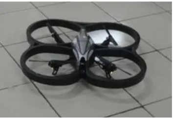
In this research AR.Drone quadcopter and a com-puter with standard Wi-Fi interface were used. The drone consists of two cameras, some other sensors, four propellers and control board. It has carbon fiber support structure so it is quite light-weight. The battery can provide enough energy to make AR.Drone flying continuously up to ±10 minutes. When the drone power is being switched on, an ad-hoc Wi-Fi appears and a computer can connect to it. After the connection has established, the user may control the drone and get the infor-mation such as altitude, battery status and other sensors data. The AR.Drone has two body cover (called hull), outdoor and indoor hull. The AR. Drone with outdoor hull can be seen at Figure 1.
Because the AR.Drone has limited hardware performance (to run many processes quickly), all computation processes are running in the compu-ter. So, the drone only know where to move from the information send by the computer via Wi-Fi while continuing to capture images continuously by using its camera. The AR.Drone has two came-ras. The first camera is on the front side and the other camera is at the bottom. The bottom camera was used to implement object detection and track-ing system in this research.
The system was built and run on Robot Ope-rating System (ROS) environment and developed using C++ programming language. ROS is an op-en source meta-operating system designed to bui-ld the robot systems [10]. With ROS, we do not
ROS uses the concept of peer-to-peer communica-tion network between programs. So, some prog-rams could run simultaneously to do the task.
In this research for example, we run some programs to do tracking process. Those programs are the driver of AR.Drone, object detection mo-dule and position control program. The driver for the drone we used was AR.Drone Brown package on ROS. Object detection module and position control module that we used were developed by ourselves. The overall system in one time running can be seen at Figure 2. That system run continu-ously over time, so each specific time, the system process images captured by AR.Drone and give coordinate message.
For basic image handler and processing, we used OpenCV (Open Computer Vision) library with ROS. That library is in vision_opencv stack which consist of several packages [11]. One of the most important package in that stack is cv_bridge that has task to bridge between ROS image mes-sage and OpenCV data structure.
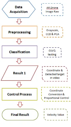
We will give brief description about some methods we used. First of all, we used standard grayscaling from raw images and then produced binary image from the grayscale image with fixed threshold. After that we process the binary image with Centroid-Contour Distance (CCD) algorithm. This is used for getting features from an image base on object's contour. The features are obtained by measuring the distance from a fixed point to surrounding points at the object contour. Wang et. al. used this technique to get features from leaf image which is a single object (for image detec-tion/recognition system) [12]. We used this tech-nique because our targeted object (the cap) recog-nition is near characteristic with leaf recogrecog-nition. Figure 3 illustrades CCD algorithm. We will des-cribed more about the implementation of this al-gorithm in Section 4.
After we got CCD features, we used the po-pular Principal Component Analysis (PCA) algo-rithm to further reduce the features. PCA is a tech-nique that consist of statistics and linear algebra concepts, especially those are related to dominant Eigen vectors [13]. Let we describe this algorithm in brief explanation.
First of all, we find averages (means) from the matrix data and then we calculate their covari-ance. After we got the covariance matrix, we de-compose the Eigen values with their correspond-ing Eigen vectors from that matrix. The decompo-sition is as the following equation(1).
𝑆𝑆𝑛𝑛=𝜆𝜆̅𝑈𝑈𝑛𝑛 (1)
In that equation, 𝑆𝑆𝑛𝑛 is covariance matrix, 𝜆𝜆̅ is Eigen values and 𝑈𝑈𝑛𝑛 is Eigen vectors which corre-spond with the values. We modified methods from JAMA: A Java Matrix Package [17] to become functions in C / C++ in this process. After that, we sorted the Eigen values from biggest to smallest value so their corresponding Eigen vectors follow them. After that we discard some small Eigen va-lues and vectors (from smallest to a number of th-at). Finally, we multiply the original data matrix with reduced Eigen vector matrix. From that oper-ation, we get the final reduced data matrix. The flow of the PCA process can be seen at Figure 4.
Data that has reduced by PCA process is used for neural network training/testing process using Generalized Learning Vector Quantization (GLVQ) algorithm. The GLVQ algorithm was de-veloped by A. Sato and Yamada in 1995 [8]. This algorithm is variation of Learning Vector Quanti-zation (LVQ) which assured convergence even though the data is not sorted. This is happening because the method is based on cost function min-imization, i.e. miss-classification error with opti-mization of gradient descent [15].
The process is started by calculating miss-classification error using equation(2).
𝜑𝜑(𝑥𝑥) = 𝑑𝑑1−𝑑𝑑2
𝑑𝑑1+𝑑𝑑2 (2)
In this formula, 𝑑𝑑1 and 𝑑𝑑2 is the distance of win-ner and runwin-ner-up class. After we get the error, we use sigmoid function as cost function. The
func-tion use that error as one of its parameters. The ot-her parameter is the iteration (𝑡𝑡). The function is as the following equation(3).
𝑓𝑓(𝜑𝜑,𝑡𝑡) = 1
1+𝑒𝑒−𝜑𝜑𝜑𝜑 (3) Then, the sigmoid function is differentiated to get "gain factor" for weight update process usi-ng equation(4).
𝛿𝛿𝛿𝛿
𝛿𝛿𝛿𝛿=𝑓𝑓(𝜑𝜑,𝑡𝑡)(1− 𝑓𝑓(𝜑𝜑,𝑡𝑡)) (4) From equation(4), the weight of winner and run-ner up in neural network's neurons can be updated using the equation(5) and equation(6).
𝑤𝑤1← 𝑤𝑤1+𝛼𝛼𝛿𝛿𝛿𝛿𝛿𝛿𝛿𝛿(𝑑𝑑1+𝑑𝑑𝑑𝑑22)2(𝑥𝑥 − 𝑤𝑤1) (5)
𝑤𝑤2← 𝑤𝑤2− 𝛼𝛼𝛿𝛿𝛿𝛿𝛿𝛿𝛿𝛿 𝑑𝑑1
(𝑑𝑑1+𝑑𝑑2)2(𝑥𝑥 − 𝑤𝑤2) (6)
In that formula, 𝑥𝑥 is the data and 𝛼𝛼 is learn-ing rate. Equation(5) and (6) is for trainlearn-ing proce-ss. For testing process, the LVQ family algorithm only used distance calculation formula to find Eu-clidean distance.
In tracking process, we used the proportional controller to control the velocity. This controller is used because sometimes, drastic changes of fixed motor controller does not produce a smooth con-trol behavior [9]. The formula of proportional co-ntroller is as given by equation(7).
Figure 3. Illustration of Centroid-Contour Distance (CCD).
Figure 4. Principal Component Analysis (PCA) process flow
𝑅𝑅(𝑡𝑡) =𝐾𝐾𝑃𝑃(𝑣𝑣𝑑𝑑(𝑡𝑡)− 𝑣𝑣𝑎𝑎(𝑡𝑡)) (7) In that formula (that always run over time 𝑡𝑡), 𝑅𝑅 is the motor output, 𝑣𝑣𝑑𝑑 is desired velocity and 𝑣𝑣𝑎𝑎 is actual velocity. The most important compo-nent of this system is 𝐾𝐾𝑃𝑃, constant value / "con-troller gain". This value will decide the con"con-troller behavior. The schematic of P controller can be se-en in Figure 5.
The difference between desired and actual velocity is the error that want to control. That er-ror than multiplied by 𝐾𝐾𝑃𝑃 to produce the output. The bigger the value of 𝐾𝐾𝑃𝑃, the response will be faster. However, that value should still be restrict-ed because if it is too big, it will cause oscillation on the system [9].
Data Preparation
After literature study, data preparation consist of images which representing the class of cap and non-cap. We captured the images manually by the AR.Drone bottom camera. There are some criteria that must be concerned in capturing the images because they will decide whether the data good or not. Those criteria are: 1) The cap (object) should be contrasted with the background; 2) The
combi-nation of hat orientation must be considered; 3) The distance between cap and the AR.Drone cam-era must be 1 meter. Because in the experiment the drone set to only fly 1 meter above the object.
One of the raw image we got by the size of
176 × 144 pixels can be seen at Figure 6. That image then cut to become 70 × 70 pixels because with that size in 1 meter distance, the cap is fully shows in a good proportion. So, the image of this size will be used in the experiment. Some cut ima-ges can be seen at Figure 7.
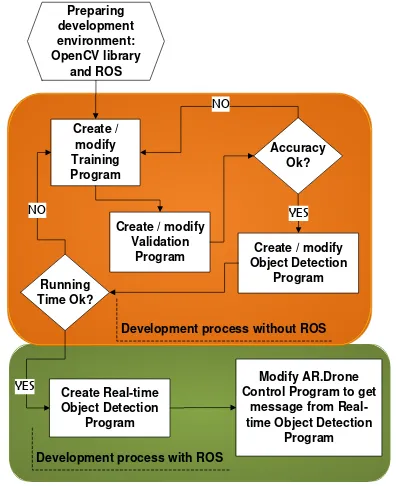
System Development Process
After we got the data, we developed the system to do object detection and tracking. The big picture of the development process can be seen at Figure 8. In the development process, we divided the process into two big steps, without ROS (we call-ed Stage 1) and with ROS (we callcall-ed Stage 2). We will describe the process step by step.
The first thing we did before building the co-de is preparing the environment and library (ROS and OpenCV). After the installation step was suc-cessfully done, we develop the training program which consists of pre-processing module and neu-ral network module. In pre-processing module we used image processing techniques and feature ex-traction algorithm (PCA) that already described in Section 2. In neural networks module, we imple-mented GLVQ training formula that also describ-ed in Section 2.
In fact, the goal of training program is to get sorted eigen vectors and weights of neural netwo-Figure 6. Full image captured by AR.Drone bottom
camera.
(a)
(b)
Figure 7. Sample of cut images: (a) cap images, (b) non-cap images.
Program Object Detection Create / modify
Program Running
Time Ok?
YES
Development process without ROS
Create Real-time Object Detection
Program
Modify AR.Drone Control Program to get
message from Real-time Object Detection
Program Development process with ROS
rk neurons. So we described this from the first
st-ep to the end. First of all, the program read the da-ta as folders of 70 × 70 pixels images that already divided into classes (cap and others). The images from that folder are loaded one by one by the function from OpenCV, cvLoadImage. By using this function, we chose the data we want to use, either BGR (blue-green-red) or grayscale [16]. In this implementation, we used grayscale image be-cause later technique we used (CCD) is consider about the shape and not the colors.
After the grayscale image has gotten, the ne-xt step is convert it into two values only, 0 and 255. To do that, technique named gray-level slic-ing (simple thresholdslic-ing technique for image) is used. With this technique, some range of graysca-le value become low value and the others become high value [14]. We considered the low value is 0 (totally black) and the high value is 255 (white).
After the image only has two values, it then directed to Centroid-Contour Distance (CCD) pro-cess. As we already described in Section 2, this method is calculating distance of points in contour of object to a pre-decided fixed point. In this pro-cess we decided the fixed point is the coordinate of 35 × 35 in pixel of image. Then, we decided to
get the distance for every 1 degree, so we will get 360 feature in full circle. The illustration of the fe-atures can be seen at Figure 3. The process from image reading to CCD run continuously until all images are processed. For every image processing steps, the data with label (class) is stored in matrix data.
After we got labeled data that has features from CCD process, we further reduced the feature with PCA. We did this because we want the run ti-me in one cycle process as short as possible at real-time run using AR.Drone. The eigen vectors reduce the feature in this process and also stored in a file named eig_vec.csv to reduce feature at testing and real-time run later.
After PCA process, the data is processed with GLVQ algorithm. This is the last step in the training program. The architecture of neuron for this process can be seen at Figure 10. From the process, we will get weights of neurons and store those values in a file named bobot.csv that will be used in testing and real-time run.
As we seen at Figure 8, after we finished wi-th training program, we went to program valida-tion. This validation program will produce the ou-tput as percentage of accuracy. Process from read-ing the data to CCD process is same with trainread-ing program. In PCA step, the data matrix is directly multiply by Eigen vectors from eig_vec.csv. In GLVQ step, the features are directly compared with the weights from bobot.csv by using euclide-an disteuclide-ance. For every true classification, the "hit" then add by 1. After the data finished processed with neural network testing step, the hit then di-vided by the number of data. That operation will produce accuracy. If the accuracy is not really sa-tisfying, we modified some parameters in training Figure 9. Stage 1 program flow.
Figure 10. Neural network architecture in experiment.
program like number of CCD features, number of features after PCA learning, learning rate or the number of learning cycle (called epoch).
After we already satisfied with the accuracy, we built/modified object detection program. This program reads the image of 176 × 144 pixels size instead of folders of 70 × 70 pixels images. The output is object coordinate in that pixel area if an object has been detected. The most important thi-ng about this program is this program must run in reasonable time, which is under 1 second. It is be-cause this program will modified to real time ob-ject detection program using ROS. Real time ro-bot application must be fast enough to response, so we should not move to the next step of devel-opment if the running time still not satisfying.
To fulfill the requirement regarding running time, we propose to only check some grids of
70 × 70 pixel size in full 176 × 144 pixel size. Because of that, we named this step as "Grid Che-ck". The rule is we only chose 19 grids to be chec-ked. Illustration of Grid Check can be seen at Fig-ure 12. We divided the grids from level 0 to level 2. It checked from center of image to its surround-ing area. In the experiment ussurround-ing AR.Drone, it sh-owed great performance that allows the drone res-ponse quickly in reasonable movements. The ove-rall of flow program without ROS can be seen at Figure 9.
In the implementation using ROS, the first thing we must do in this step is modifying the pre-vious object detection module. This module must
receive image message from AR.Drone that is ar-dorne/image_raw. It is a bit different with previ-ous program which get offline image from the lo-cal storage. Besides that, some functions and vari-ables must be changed or modified. Actually, this task is not really hard if the programmer already keep up with ROS.
The last task in development process was modifying the AR.Drone control program. This program must get object coordinate message from real time object detection program. Since the ob-ject coordinate is in pixel coordinate, in control program, coordinate conversion must be done fir-st. The coordinate conversion use the following equation(8) and equation(9).
𝑥𝑥𝑣𝑣𝑒𝑒𝑣𝑣=𝑐𝑐𝑦𝑦− 𝑦𝑦𝑝𝑝𝑝𝑝𝑝𝑝 (8)
𝑦𝑦𝑣𝑣𝑒𝑒𝑣𝑣=−(𝑥𝑥𝑝𝑝𝑝𝑝𝑝𝑝− 𝑐𝑐𝑝𝑝) (9)
In that equations, 𝑐𝑐𝑝𝑝 and 𝑐𝑐𝑦𝑦 is the center of
176 × 144 pixel, i.e. 88 and 72. To see this more clearly, we should refer to Figure 13 and 14. After we got the velocity, we used proportional control-ler to make a smooth movement. From this point, we said that the development process was done. The overall flow of program without ROS can be seen at Figure 11.
Figure 12. Grid Check.
Figure 13. Pixel coordinate in AR.Drone bottom camera.
3. Results and Analysis
In this section, we showed the experimental result we did. In the experiment, we used packet of trai-ning and testing data (in image folders). Traitrai-ning data images can be seen at Figure 15 and the test-ing data can be seen at Figure 16.
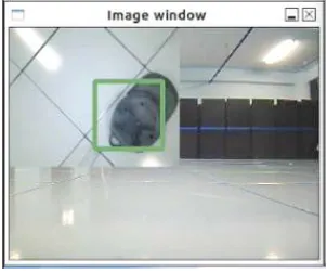
The experiment result can be seen at Table 1. In that table, we conclude that the experiment pro-duce good results except for PCA which remains 1 feature. Because the parameter of PCA in 200 features is good and run quickly, we choose that for real time object detection. For the result in real
time detection using ROS, we can see the experi-ment and screen shot at Figure 17 and 18.
4. Conclusion
Experiment results show that the implementation of image processing and neural network GLVQ algorithm to do object detection and tracking was success. The running time is short and it have go-od accuracy in GLVQ validation that is more than 90 percent in average. The running time, which is under 1 millisecond, that shows at Table 1, is very good for real time application that need quick res-ponse. This short time is also coming from great contribution of feature extraction from CCD tech-nique after doing some image processing techni-ques which are grayscaling and thresholding. The Figure 15. Training data (trainNonCap: first 4 rows,
trainCap: the last row).
Figure 16. Testing data (testNonCap: top rows, testCap: bottom row).
TABLEI EXPERIMENTALRESULT
Experi-ment Testing Data PCA Accuracy Detected Running Time
1 testNonCap and testCap 360 92.54% Yes 1.24 ms
2 testNonCap and testCap 1 74.63% No -
3 testNonCap and testCap 300 92.54% Yes 0.91 ms 4 testNonCap and testCap 200 92.54% Yes 0.88 ms
5 testNonCap and trainCap 200 100.00% Yes 0.88 ms
Figure 17. Real experiment using AR.Drone.
This work was also coordinated with big research under research fund which was received by Dr. Petrus Mursanto and Dr. Eng. Wisnu Jatmiko in the Faculty of Computer Science Universitas In-donesia. Gratitude is also addressed to some stu-dents in the Lab of Computer Networks, Architec-ture and High Performance Computing in the fac-ulty with good discussions and some help for pre-paring the experiments.
References
[1] E. Marris, “Fly, and Bring Me Data,” in
NATURE, Vol. 498, ch. News Feature, pp.
156–158, Macmillan Publishers Limited, Ju-ne 2013.
[2] J. H. Choi, Won-Suk Lee and H. Bang, “Hel-icopter Guidance for Vision-based Tracking and Landing on a Moving Ground Target,”
in 11th International Conference on Control,
Automation and Systems, pp. 867–872,
Dae-jeon, Korea, 2011.
[3] A. Reid, F. Ramos and S. Sukkarieh, “Multi-Class “Multi-Classification of Vegetation in Natural Environments Using an Unmanned Aerial System,” in International Conference on
Ro-botics and Automation, pp. 2953–2959,
Sha-nghai, China, May 2011.
[4] J. Gleason, A. V. Nefian, X. Bouyssounous-se, T. Fong and G. Bebis, “Vehicle Detection from Aerial Imagery,” in International
Con-ference on Robotics and Automation, pp.
2065–2070, Shanghai, China, May 2011. [5] M. Siam, R. ElSayed and M. ElHelw,
“On-board Multiple Target Detection and Track-ing on Camera-Equipped Aerial Vehicles,” in
International Conference on Robotics and
on Applied Sciences & Technology, pp. 258–
264, Islamabad, Pakistan, January 2009. [8] A. Sato and K. Yamada, “Generalized
Learn-ing Vector Quantization,” in Advances in
Ne-ural Information Processing Systems (NIPS),
Vol. 7, pp. 423–429, 1995.
[9] T. Bräunl, Embedded Robotics, Mobile Ro-bot Design and Applications with Embedded
Systems, 2nd ed., Springer, Germany, 2006.
[10] Documentation, http://www.ros.org/wiki, re-trieved June 18, 2012.
[11] vision_opencv, http://wiki.ros.org/vision_op encv, retrieved July 3, 2014.
[12] Z. Wang, Z. Chi and D. Feng, “Shape based leaf image retrieval,” in IEEE
Proceedings-Vision, Image and Signal Processing, Vol.
150, No. 1, pp. 34–43, 2003.
[13] Bernard Kolman and David R. Hill,
Elemen-tary Linear Algebra 8th Edition, Pearson
In-ternational Edition, New Jersey, 2004. [14] Rafael C. Gonzales and Richard E. Woods,
Digital Image Processing Second Edition,
Pearson International Edition, New Jersey, 2002.
[15] I Made Agus Setiawan, “Sistem Pengenalan Kelainan Aritmia menggunakan Metode Fuzzy-Neuro Generalized Learning Vector Quantization,” Master Thesis, Faculty of Co-mputer Science, Universitas Indonesia, 2011. [16] Gary Bradski and Adrian Kaehler, Learning OpenCV - Computer Vision with the OpenCV
Library, O’Reilly Media, Inc., Sebastopol,
CA, 2008.