8-9 November 2011, Bandung, Indonesia
Development of Fluxgate Sensors and Its
Applications
Mitra Djamal1, Edi Sanjaya2, Yulkifli3 and Ramli4
1Department of Physics, Institut Teknologi Bandung, Bandung, Indonesia (Tel : +62-821-1659-1960; E-mail: [email protected])
2
Department of Physics, UIN Syarif Hidayatullah, Jakarta, Indonesia (Tel : +62-813-8250-5818; E-mail: [email protected]) 3
Department of Physics, Universitas Negeri Padang, Padang, Indonesia (Tel : +62-813-6341-3004; E-mail: [email protected]) 4
Department of Physics, Universitas Negeri Padang, Padang, Indonesia (Tel : +62-813-2102-9889; [email protected])
Abstract-Fluxgate sensors were firstly developed in the 1930 and were rapidly used for many of applications. These sensors have been used in robotic space probes to analyze, map and monitor the Earth's magnetic field and the other planets. They are also used in geological, aerospace, underwater navigation, land navigation and submarine detection. The future development of fluxgate is reducing their size and making them compatible with micro/nano-electronic technology. In this paper, we give a reviews recent development in the manufacturing technology and applications of fluxgate sensors.
Keyword: Fluxgate sensor, Hybrid technology, Magnetic sensor, Magnetometer, Pick-Up coil, PCBs technology.
I. INTRODUCTION
Fluxgate magnetometers have been used for robotic space probes to analyze, map and monitor the magnetic fields of the earth and other planets. They are also used in geological prospecting, aerospace navigation, underwater navigation, land navigation and submarine detection.
Fluxgate sensor is one of magnetic sensor that still attracts the attention of many researchers. This is caused by advantages of fluxgate sensor which is more sensitive [1,2,3] and more precise [4]. Fluxgate has been used as magnetic sensors since the 1930's [5]. Trend of the development of fluxgate is to reduce their size and to have better manufacturing technology. Reducing the size and weight of fluxgate sensors is essential in microelectronics industry.
Formerly, the use of fluxgate sensor is quite limited only to detect and measure magnetic fields with low frequencies. With the tremendous development of fluxgate, the sensor can measure magnetic fields as weak as Earth's magnetic field (± 45 T) [6]. Nowadays, fluxgate sensors have been developed as an instrument of geophysics, detection of ferromagnetic objects [7], the space instruments [8], and the instrument bio-magnetic [9]. At space application, the fluxgates are used as payloads of satellites for the in-orbit measurement of the Earth magnetic field, for navigation and for measurement of interplanetary magnetic fields.
Resolution and precision of fluxgate sensors has also been improved. In 2003, as reported by Ripka [10], a resolution of 100 pT and precision of 10 nT in commercial devices can be improved to achieve a resolution of 10 pT and the precision of 1 nT. In addition, the sensitivity of fluxgate is also increased. Recently, Janosek and Ripka [3], reported a sensitivity of fluxgate sensor reaches 120.000 V/T using PCB technology by controlling the excitation current. Ripka et al [11] reported a sensitivity of fluxgate sensor for 30 mV/ T using multi wire core. Today, their sensitivity spans a wide range from 10-10 to 10-4 T.
The working principle of a fluxgate sensor is based on non-linear properties of ferromagnetic materials, where its permeability changes by a change of magnetic field around the sensor [12]. Magnetic field strength measurements are based on the relationship between magnetic field strength H against magnetic field induced B. If B is generated from the input H of the wave pulse back and forth, then in a state of saturation at the output of B will occur even and odd numbered harmonic wave. In the even-numbered harmonic wave there is a second harmonic wave, which is proportional to the external magnetic field. The direction of this wave is in the direction of the external magnetic field [13,14,15].
In this paper, we review a recent development of fluxgate sensors, including manufacturing technology and their applications.
II. THEORETICAL BACKGROUND
The fundamental principle of functional fluxgate system is the ratio of the external magnetic field (Bext) as measured and reference magnetic field (Bref) [16]. Changing the magnetic field strength into electrical signals can be done directly to measure Bext. Fluxgate magnetic sensor does not use a direct way, but uses a reference magnetic field Bref for comparison with the measured magnetic field Bext using containers filled with core material. This principle is shown in Fig. 1.
8-9 November 2011, Bandung, Indonesia
Fig. 1. Magnetic field measurement principle: a) straightforward; b) using Bref
reference magnetic field Bref as comparator for measured magnetic field Bext
(modified from [16]).
Fluxgate element consists of ferromagnetic core and two coils consist of excitation and pick-ups coils. Excitation coil is a coil that is used to generate the excitation magnetic field. The excitation coil is the same as in the solenoid, where the magnetic field arising from the presence of electric field (Faraday's law).
A good coil configuration will increase the accuracy because the measured field will be not distorted that come from the core. For more details, working principles of fluxgate measurements can be seen in Fig. 2.
Working principle of fluxgate magnetic sensor; (a) Field of excitation without external magnetic field Bext = 0, (b) excitation field with the external magnetic field Bext 0, (c) in a state of saturation magnetization curve in Bext = 0; (d) in a state of saturation magnetization curve in Bext 0; (e) changes in flux with time at Bext = 0; (f) change in flux with time at Bext
0; g) sensor output voltage at Bext = 0; (h) The sensor output voltage at Bext 0.
Fig. 2. Fluxgate working principle (adapted from [17]).
Figure 2 shows that the fluxgate sensor works based on the differential principle. The interference/noise from environment such as temperature or other environmental influences will eliminate each other and the sensor can measure extremely
weak magnetic fields. To overcome the interference of high frequency signals, sensors mounted on a second order low pass filter. The detection of the second harmonic component of the sensor output voltage is performed by means of a phase sensitive detector usually preceded by a bandpass filter is the most usual method.
III. MANUFACTURE TECHNOLOGY OF FLUXGATE SENSOR
Since its introduction in 1930s to the present, the fluxgate has undergone significant developments both in technology manufacture such as: fluxgate element, signal processing circuit, model of geometry, and its applications. Various technological approaches to improve the performance of fluxgate such as: sensitivity, accuracy, resolution, field strength and homogeneity have been carried out. A technological approach has been developed to optimize the fluxgate.
A. Conventional Technology
In conventional technology, wire of core excitation and pick-up coil are wrapped manually. Metglass or Vitrovac in ribbon-shaped with a width and thickness of mm scale is normally used as the ferromagnetic core. Two cores consisting of three layers tape of Vitrovac/Metglas are stacked parallel thus increasing the core thickness. After coated with an insulator the core is wrapped by winding wire. Winding wire is composed for excitation and the pick-up coil. Winding excitation is located at the edge of the flanking secondary winding or pick-ups.
The number of windings is inversely proportional to the sensitivity of the sensor. So that it only takes little windings to get high sensitivity. The often used shapes of ferromagnetic core of fluxgate element are single-core rod, double rod-core, ring-core-core and racetrack. [4, 18, 19]. Fig. 2 shows a design of fluxgate using conventional technology.
Fig.2. Geometry of fluxgate sensor: (a) mono pick-up and (b) double pick-up
[20,21]
B. PCBs Technology
8-9 November 2011, Bandung, Indonesia
magnetic core. The sensor has a permeability of 100,000 and a sensitivity of 18 V/T at a frequency of 10 kHz [23].
Then, PCBs technologies was developed at the Univ. Complutense de Madrid and Madrid Polytechnical University (Spain) by Perez, L. et.al., which combines technology with the electrodeposition PCBs in 2004. These sensors integrate the excitation coil and ferromagnetic core using amorphous ferromagnetic materials Co-P. These sensors have high sensitivity around 160 V/T with a linear range (0-250 T) [24].
Lucas, et al (2006) reported a fluxgate sensor based on multilayered Co-P alloy as ferromagnetic core. They obtained that coercivity at high frequency is only due to eddy currents [25].
PCBs technology has a simple process and relatively inexpensive. But the disadvantage is a larger size compared with conventional technology, especially when compared with micro technology. Manufacturing process of fluxgate sensor with PCBs technology are shown in Fig. 3.
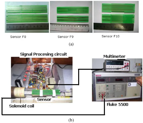
The result of PCB sensor element manufacturing shown in Figure 3.(a); Sensor F8 (Double layer, double pick up, Core : Vitrovac VC 6025Z and sensor size = 12 x 2,4 x 0,4 cm), Sensor F9 (Double layer, Single pick up, Core: Vitrovac VC 6025Z and sensor size = 12 x 2,4 x 0,2 cm), and Sensor F10 (Four layer, Single pick up, Core: Vitrovac VC 6025Z and sensor size = 8,7 x 2,5 x 0,5 cm).
Sensor fluxgate is characterized using Fluke 5500 calibrator as generator of the current and the solenoid as generator of the magnetic field. Set-up of sensor response measurement is shown figure 3.(b).
(a)
(b)
Fig.3. Schematic diagram of fluxgate fabrication process; (a) Design of PCB fluxgate sensor element, (b) Set-up of sensor response measurement from
external magnetic field [26].
C. Microfabrication
Wire as a material excitation and pick-up coil as well as the ferromagnetic core made using a variety of micro technology process. The micro technology including among others:
electroplating, chemical etching, flex-foil, photolithography, photoresist and evaporation. Some of the researchers who developed this technology are Kawahito, et al (1994) [27] and (1996) [28], Ripka, et al. (2001) [29, 30], Wang, et al., (2006) [31], Fan., et al. (2006) [32] and Zorlu, et al. (2008) [19].
Park, et.al [33], has reported the fabrication of fluxgate sensor with magnetic core from electroplated Ni0.81Fe0.19 under external magnetic field 2000 G. They obtain the permeability of fluxgate sensor is 1250 and have a linier response between −100 to +100T then sensitivity 210 V/T. Baschirotto, et.al [34], has been using sputtering deposition for microfabrication of fluxgate. They showed that the magnetic properties of the core, has decreased after the deposition. Sensitivity of sensor are 0.45 mV/T and linearity about 1.15% at scale ± 50 T.
Zorlu, et.al [35], has been developed a micro technology using electroplating and photoresist. They obtain sensitivity of sensor with 18 cascaded cores are 623 V/mT and linier range about ±300 T.
Micro technology has a very complex process so that the cost of the manufacturing process is relative expensive. In addition the resulting sensitivity is quite low due to small cross-sectional area. To obtain high sensitivity required of high frequency, and limitations of coils number in the solenoid [36,37].
According to Ripka [38], the use of ferromagnetic core in the form of bulk soft magnetic core is better than thin films core, because the large magnetic field measured depends on the cross-sectional area of the core. Kubik, et al [12] obtain that the sensor the micro technology process has a big noise compared to the PCBs technology.
D. Hybrid Technology
The combination of the above technologies is called the hybrid technology [39]. Manufacturing process of fluxgate sensor with hybrid technology is shown in Fig. 4. Several researchers that use this hybrid technology are: Belloy, et al [40], Tipek, et al [41] and Perez, et al [42].
8-9 November 2011, Bandung, Indonesia
Tipek, et.al [43] reported a preparation of the sensor by PCB technology with ring-shaped core made with electrodeposited. The resulting sensor has a sensitivity of 1800 V/T for pick-up coil unturned and 13 100 V/T for tuned pick-up coil at a frequency of 150 kHz.
Perez et al [42] combined the PCB technology by electrodeposition to create a fluxgate sensor in 2004. They integrate the excitation coil and ferromagnetic core using amorphous ferromagnetic materials Co-P. This sensor has a high sensitivity about 160 V/T by linier range of 0-250 T.
In 2009, Kubik et al [44] using PCB technology and electroplated by developing multilayer material PCBs up to 12 layers. The resulting sensor has permeability 2300 at 50 kHz and sensitivity 90 V/T in x axis and 112 V/T in y axis, and z
axis 198 V/T. The difference between the value of the sensitivity of the x and y-axis is caused by the anisotropy of core material, while the difference in the z axis is caused by the demagnetization factor. Janosek et al [45], make a fluxgate sensor with the dual core lamination by race tracks and five-layer PCB. This sensor has a sensitivity of 615 V/T for 650mA peak-to-peak excitation current with non-linearity 0.5%.
IV. APPLICATIONS OF FLUXGATE SENSOR
Fluxgate sensors have been used for the measurement of weak magnetic field, with a single coil pick-up [15]. Sensor output is shown in Fig. 5. From Fig. 5 it appears that there is in the linear region between-18µT magnetic fields up to 18µT, in this area, output voltage proportional to the measured magnetic field, thus the magnetic sensor works well in this area.
Fig. 6. Sensor output voltage as function of magnetic field
Other application of the fluxgate is a proximity sensor [46]. Change the distance between the target with the sensor is inversely proportional to the output characteristic of the sensor. The farther from the target then the output voltage characteristics are smaller and vice versa. Fluxgate sensors have been developed capable to detect changes in the distance with a resolution of 10 m, the absolute error 0.12 m and relative error 2.5%.
Fluxgate elements have also been applied to the vibration sensor [47,48]. The design of mechanical system of vibration measurement is shown in Fig. 7. Application for vibration
measurement was performed using two techniques: direct and indirect measurement techniques. Based on the direct measurement technique, the sensors can measure the frequency up to 500 Hz, with an error 0.58%. In the other hands, for the applications in low frequency, the sensor can measure the frequency from 0.14 to 1.15 Hz with 1.3% error. In the vibration measurements with the indirect technique the sensor output signal is depend on the mechanical vibration parameter which used such as length of arm (L), seismic mass of the object (m) and the sensor probe distance from vibration object (y). Sensor design for measurement with L=5cm, m=0.28g and y=2cm producing the resonance frequency around 38-40 Hz. To avoiding the resonance frequency, measurement data analysis divided into two parts, in the frequencies below 38 Hz and above 40 Hz. Based on the selected mathematical approaches model resulting the relative error is 4.39% for the region under the resonance frequency and 5.06% for the region above the resonance frequency.
Fig.7. The design of mechanical system (a) and photo equipment of low frequency vibration measurement
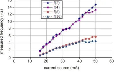
Fluxgate elements have been applied to measurement of angular velocity [49]. Fluxgate sensor placed at a distance of 1 cm and 2 cm of the magnetic disc. Magnetic disc rotated by a motor-DC. The results of measurements of the frequency and the current source are shown in Fig. 8. As seen in Fig. 8 the frequency response for the number of magnetic objects 2 and 4 higher than at 8 and 16. This is caused by the mass of the magnet attached to the disc. This angular velocity sensor has a relative error of less than 5%.
Fig. 8. Frequency curves of magnetic disc
8-9 November 2011, Bandung, Indonesia
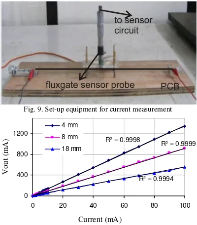
on the PCB-stripe. Measurements are carried out for different distance, e.g. 4mm, 8mm, and 18mm. The measurement set-up is shown in Fig. 9. The sensor characteristic for small current (0-100mA) is shown in Fig. 10. It can be seen that there is a linear relationship between current and output signal.
Fig. 9. Set-up equipment for current measurement
Fig. 10. Sensor output signal as functions of current
Magnetic sensor offers a very attractive alternative for a non-contact displacement measurement [51]. The measurement system as shown Fig. 11. It gives more benefits in terms of cost, eases of deployment and maintenance, and enhanced measurement capabilities. By applying magnetic sensor, smaller displacement can be detected rather than the ordinary
Fig. 11. The measurement system of distance
IV. CONCLUSION
Since the 1930's, fluxgate sensors have undergone tremendous development, both in terms of manufacturing technology and its application. Nowadays, the research on fluxgate sensor is to minimize their size and make it compatible with micro-electronic technology.
ACKNOWLEDGEMENT
The work was supported by the Directorate of Higher Education, Indonesian Ministry of Education under grant “Hibah Bersaing” no 080/H35.2/PG/HB/2009 and Research KK-ITB No.: 262/K01.7/PL/2009. controlled excitation, Sensors and Actuators A151, pp.141–144, 2009. [4]. P. Ripka (Ed), Magnetic sensors and magnetometers, Artech, London,
2001.
[5]. P. Ripka, Review of fluxgate sensors, Sensors and Actuators A33, pp.129-141, 1992.
[6]. F. Kaluza, A. Gruger and H. Gruger, New and future applications pf fluxgate sensors, Sensors and Actuators A,106. pp.48-51. 2003.
[7]. H.S. Park, J.S.Hwang, W.Y.Choi, D.S.Shima, K.W.Na, and S.O.Choi, Development of micro-fluxgate sensors with electroplated magnetic cores for electronic compass, Sensors and Actuators A,114, pp.224-229 .2004. [8]. M.H. Acuna, Space-based magentometers, Rev. Sci. Instrum.73 (11). pp.
3717–3736, 2002.
[9]. P.Ripka and P. Navratil, Fluxgate sensor for magnetopneumometry,
Sensors and Actuators A,60, pp.76-79.1997.
[10]. P. Ripka, Advances in fluxgate sensors, Sensors and Actuators A,106, pp. 8-14, 2003.
[11]. P. Ripka. X.P. Li and J. Fan, Multiwire core fluxgate, Sensors and Actuators A156. pp. 265–268. 2009.
[12]. J. Kubik, L. Pavel, and P. Ripka, PCB recetrack Fluxgate Sensor with Improved Temperatur Stability, Sensors and Actuators A, 130, pp 184-188. 2006.
[13]. W. Gopel, J. Hesse, and J.N. Zemel, Sensors: A Comprehensive survey, magnetic sensors, VCH Publishers Inc, 1989.
[14]. S. Kawahito, H. Sato, M. Sutoh and Y. Tadokoro, High resolution mikrofluxgate sensing element using closely coupled coil structures,
Sensors and Actuators A,54, pp.612-617. 1996.
[15]. M. Djamal and R.N, Setiadi, Pengukuran medan magnet lemah menggunakan sensor magnetic fluxgate dengan satu kumparan pick up.
Proc. ITB Sains & Tek, vol. 38A, No. 2, pp. 99-115. 2006.
[16]. W. Göpel, J. Hesse, and J.N. Zemel, : Sensors, A Comprehensive Survey, Magnetic Sensors, VCH Publishers Inc., 1989.
[17]. H. Grueger, and R. Gottfried-Gottfried, “CMOS Integrated Two Axes Magnetic Field Sensors – Miniaturized Low Cost System With Large Temperature Range”, Fraunhofer Institute for Microelectronic Circuits and Systems IMS,” Preparation, Propoerties, and Applications of Thin Ferromagnetic Films, pp. 35-38, 2000.
[18]. J. Kub´ık, PCB fluxgate sensors, Dissertation Thesis, CTU in Prague, pp. 56–58. 2006.
[19]. O. Zorlu, Orthogonal fluxgate type magnetic microsensor with wide linier operation range, Dissertation Thesis, EPFL Ankara, 2008.
[20]. Yulkifli, Mitra Djamal, Khairurrijal, Deddy Kurniadi, Pavel Ripka: The Influence of the Tape-core Layer Number of Fluxgate Sensor Using the Double Pick-up Coils to the Demagnetization Factor, Proc. ICICI-BME, November, 23-25, 2009, Bandung.
[21]. Ripka, P., 2001a: Mangetic Sensor and Magnetometers, Artec House
[22]. O. Dezuari, S.E, Gilbert, E. Belloy, M.A.M. Gijs, New hybrid technology for planar fluxgate sensor fabrication. IEEE. Trans Magn. 35, pp.2111-2117. 1999.
[23]. Dezuari, O.; Gilbert, S.E.; Belloy, E.; Gijs, M.A.M. Printed circuit board integrated fluxgate sensor. Sensors and Actuator. A81, pp. 200-203. 2000. [24].L. Perez,, C. Aroca, P. Sánchez, E. López, M.C. Sánchez, Planar fluxgate
sensor with an electrodeposited amorphous core, Sensors and Actuators A
109 pp. 208–211. 2004.
8-9 November 2011, Bandung, Indonesia
[26].Yulkifli, Pengembangan Elemen Fluxgate dan Penggunaanya untuk Sensor-sensor Berbasis Magnetik dan Proksimiti, Disertasi, Institut Teknologi Bandung, 2010.
[27].Kawahito, S., Sasaki, Y., Sato, H., Nakamura, T. and Tadokoro, Y., A Fluxgate magnetic sensor with micro-selonoids and electroplated permalloy cores, J. Sensor and Actuator A, vol. A43, pp.128-134. 1994. [28]. Kawahito, S., Satoh, H., Sutoh, M. and Tadokoro, Y., High-resolution
microfluxgate sensing elements using closely coupled coil structures,
Sensor and Actuator A, vol. 54, pp. 612-617, 1996.
[29]. Ripka, P., Kawahito, S., Choi, S.O., Tipek, A. and Ishida, M., Micro-fluxgate sensor with Close core, Sensor and Actuator, A9, pp. 65-59, 2001.
[30]. Ripka, P., Choi, S., Tipek, A, Kawahito, S. and Ishida, M.,Pulse Excitation of Micro-Fluxgate, Sensors. IEEE Trans. Mag., Vol. 37, no.4, pp.1998-2000, 2001.
[31]. Wang, Y., Liu, G., Xiong, Y., Yang, J. and Tian, Y., Fabrication of the three-dimensional solenoid type micro magnetic sensor, J. of Physics:Conference Series,34, pp. 880-884, 2006.
[32]. Fan, J., Li, X.P and Ripka, P., Low Power Ortogonal Sensor with Electroplated Ni80Fe20/Cu Wire, J.of Applied Physics, 99, pp.08B3111-08B3113, 2006.
[33].Hae-Seok Park , Jun-Sik Hwang, Won-Youl Choi, Dong-Sik Shima, Kyoung-Won Naa, Sang-On Choi,Development of micro-fluxgate sensors with electroplated magnetic cores for electronic compass, Sensors and Actuators A114. pp. 224–229. 2004.
[34].A. Baschirotto, F. Borghetti, E. Dallago, P. Malcovati, M. Marchesi, E. Melissano, P. Siciliano , G. Venchi, Fluxgate magnetic sensor and front-end circuitry in an integrated microsystem, Sensors and Actuators A132
pp. 90–97. 2006.
[35].O. Zorlu, P. Kejik, W. Teppan, Micro fluxgate sensor with cascaded planar ring cores, Proceedings of the Eurosensors XXIII conference, Procedia Chemistry. pp. 630–633. 2009.
[36]. P. Ripka, S. Choi, A. Tipek, S. Kawahito, and M. Ishida, Pulse Excitation of Micro-fluxgate Sensor, IEEE Trans. Mag. 37(4), pp. 1998-2000, 2001 [37]. S.Liu, Studi on The Low Power Consumption Racetrack Fluxgate,
Sensor and ActuatorA, 130, pp 124-128, 2006.
[38]. P. Ripka, Sensors Based on Bulk Soft Magnetic Material: Advances and Challenges, Journal of Magnetism and Magnetic Materials320, pp.2466-2473, 2008.
[39]. O. Dezuari, E. Belloy, E, Scott, Gilbert and M.A.M. Gijs, New hybrid Technology for planar fluxgate fabrication, IEEE Transaction on Magnetics, 35, pp.2111-2117, 1999.
[40]. E. Belloy, S.E. Gilbert, O. Dezuari, M. Sancho, and M.A.M. Gijs, A hybrid technology for miniaturised inductive device application, Sensor and ActuatorA, 85, pp.304-309, 2000.
[41]. A. Tipek, T. O’Donnell, and J. Kubik, Excitation and temperature stability of PCB fluxgate, IEEE Sensors Journal, 5(6), pp.1264-1270, 2005.
[42]. L. Perez,, C. Aroca, P. Sánchez, E. López, and M.C. Sánchez, Planar fluxgate sensor with an electrodeposited amorphous core, Sensors and Actuators A,109, pp.208–211, 2004
[43]. A. Tipek , P. Ripk, Terence O’Donnell, and J. Kubik, PCB technology used in fluxgate sensor construction , Sensors and Actuators A, 115, 286– 292. 2004.
[44]. J. Kubik, J. Vˇcelak, T. O’Donnell, and P. McCloskey, Triaxial fluxgate sensor with electroplated core, Sensors and Actuators A 152 pp. 139–145. 2009.
[45]. M. Janoˇsek and P. Ripka, PCB sensors in fluxgate magnetometer with controlled excitation, Sensors and ActuatorsA151 pp. 141–144. 2009. [46].Yulkifli, Rahmondia N. S., Suyatno, and Mitra Djamal, “Designing and
Making of Fluxgate Sensor with Multi-Core Structure for Measuring of Proximity,” Procd. On CSSI, Serpong Tanggerang- Indonesia, 2007. [47]. M. Djamal, Setiadi, R.N. and Yulkifli: Preliminary Study of Vibration
Sensor Based on fluxgate Magnetic Sensor, Proc. ICMNS. 2008. [48]. M. Djamal., Yulkifli, dan Setiadi, A., dan Setiadi, R.N., Development of a
Low Cost Vibration Sensor Based on Fluxgate Element, International conference of the Institute for Environment, Engineering, Economics and Applied Mathematics ( IEEEAM), Malta, Itali, September, 15-17, 2010. [49]. Djamal, M. dan Yulkifli, (2009): Fluxgate Sensor and Its Application,
Proc. ICICI-BME, November, 23-25, 2009, Bandung
[50]. M. Djamal, and Rahmondia, N., S. Sensor Magnetik Fluxgate dan Aplkasinya untuk Pengukuran Kuat Arus, J. Sains dan Teknologi Nuklir Indonesia, III, pp. 51-69, 2007.
[51]. M. Djamal, and Rahmondia. N. S, “Displacement Sensor based on Fluxgate Magnetometer”, Proc. of Asian Physics Symposium, Bandung, 2006
![Fig. 2. Fluxgate working principle (adapted from [17]).](https://thumb-ap.123doks.com/thumbv2/123dok/4002105.1945525/2.612.70.297.402.591/fig-fluxgate-working-principle-adapted.webp)