• Tidak ada hasil yang ditemukan

Analisis Kestabilan Sistem Pengendalian Umpan Balik

N/A
N/A
Protected

Academic year: 2021

Membagikan "Analisis Kestabilan Sistem Pengendalian Umpan Balik"

Copied!
48
0
0

Teks penuh

(1)

Analisis Kestabilan Sistem

Pengendalian Umpan Balik

05

05

Tujuan

Tujuan: Mhs mampu menganalisis kestabilan sistem

pengendalian umpan balik

Materi

Materi:

1. Konsep Kestabilan Sistem Loop Tertutup (Stability Concept

of The Closed Loop System)

2. Persamaan Karakteristik (Characteristic Equation)

3. Kestabilan Berdasarkan Ultimate Response

4. Kriteria Kestabilan Routh-Hurwitz

(2)

Loop Tertutup

• Designing a FBC (i.e. selecting its

components and tuning its controller)

seriously affects its stability characteristics.

• The notion of stability and the stability

characteristics of closed loop systems is

therefore considered to be useful.

Notion of Stability Ξ Pemahaman Kestabilan

Stability Characteristic Ξ Karakteristik Kestabilan

(3)

The Notion of Stability

(Pemahaman Kestabilan)

• How to define about stable and unstable?

Æ A dynamic system is considered to be

stable IF every bounded input produces

bounded output

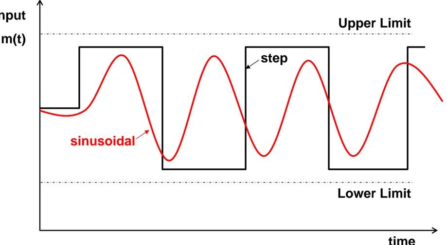
• Bounded : input that always remains

between an upper and a lower limit

Æ sinusoidal, step, but not the rump

(4)

Gambar 5.1.1. Bounded Input

Input

m(t)

time

Upper Limit

Lower Limit

sinusoidal

step

(5)

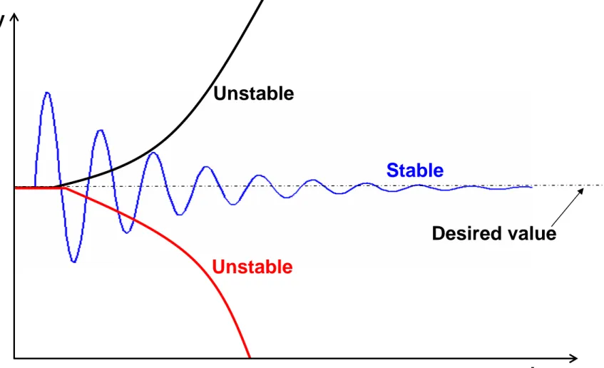
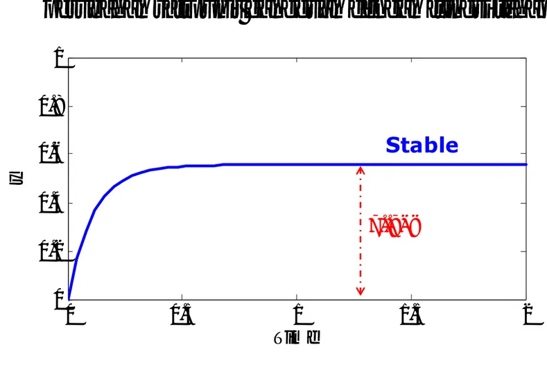
Gambar 5.1.2. Tanggapan (response) stabil dan tidak stabil

y

time

Desired value

Stable

Unstable

Unstable

(6)

Transfer

Function

• m = input, and y = output

• If G(s) has a pole with positive real part, it gives

rise to a term C

1

e

pt

which grows continuously

with time Æ unstable

)

(

)

(

)

(

s

G

s

m

s

y

=

If TF of dynamic system has even one pole with

positive real part, the system is UNSTABLE

∴ all poles of TF must be in the left-hand part

of a complex plane, for the system to be

STABLE

(7)

Gambar 5.1.3. Complex Plane

Imaginary

Real

Stable

Unstable

(8)

Example 5.1.1: Stabilization of an unstable process

with P Control

Let’s consider a process with the following response:

)

(

1

5

)

(

1

10

)

(

d

s

s

s

m

s

s

y

+

=

Pole has positive root

s – 1 = 0 Æ s = +1

y(t) = C

1

e

t

(9)

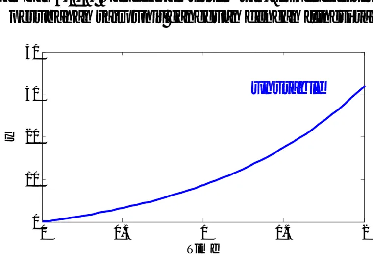
Gambar 5.1.4. Tanggapan sistem tak-terkendali terhadap

perubahan satu unit gangguan dengan fungsi tahap

0

0.5

1

1.5

2

0

10

20

30

40

Time

y

unstable

Example 5.1.1 (Continued)

(10)

The closed loop response:

(

)

(

1

10

)

(

)

5

)

(

10

1

10

)

(

d

s

K

s

s

y

K

s

K

s

y

c

sp

c

c

+

=

(

c

c

)

sp

K

s

K

s

G

10

1

10

)

(

=

(

c

)

load

K

s

s

G

10

1

5

)

(

=

Example 5.1.1 (Continued)

and

The transfer function:

The closed loop will have negative pole if

10

1

>

c

(11)

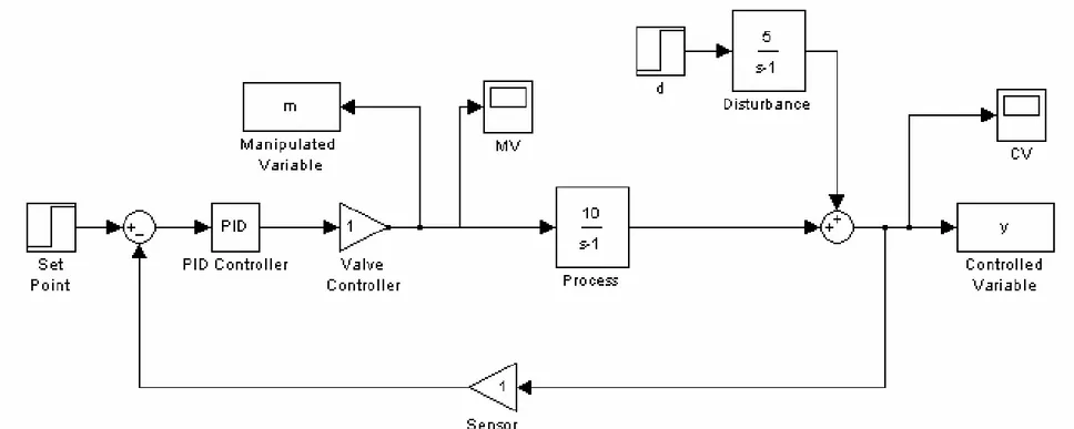
Gambar 5.1.5. Penerapan FBC

Note: P only controller with Kc = 1

Example 5.1.1 (Continued)

(12)

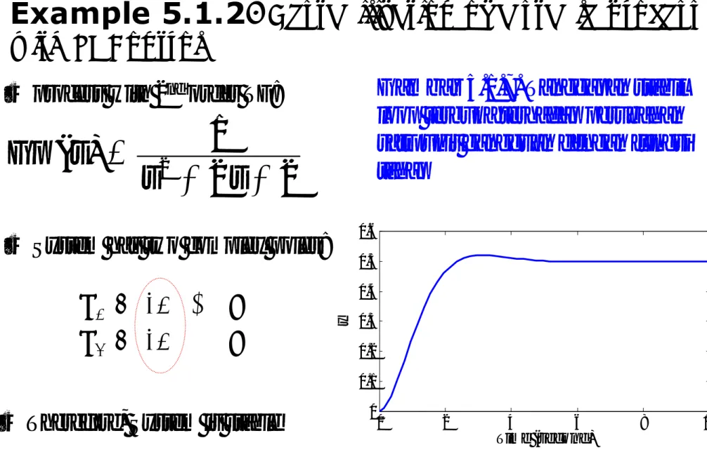
Gambar 5.1.6. Tanggapan dinamik sistem terkendali terhadap

perubahan satu unit gangguan dengan fungsi tahap

0

0.5

1

1.5

2

0

0.2

0.4

0.6

0.8

1

Time

y

Note: Regulatory problem; with Kc = 1

Stable

(13)

Example 5.1.2:

Destabilization of a stable process

with PI Control

• process with 2

nd

order TF:

2

2

1

)

(

2

+

+

=

s

s

s

Gp

• System has two complex poles:

• Therefore, System is stable

p

1

= -1 + j

p

2

= -1 − j

0

2

4

6

8

10

0

0.1

0.2

0.3

0.4

0.5

0.6

Time (second)

y

Gambar 5.1.7. Tanggapan stabil

loop terbuka terhadap perubahan

satu unit gangguan dengan fungsi

tahap

(14)

Example 5.1.2 (Continued)

• Implementation of PI Control

⎟⎟

⎜⎜

+

=

s

K

s

G

I

C

C

τ

1

1

)

(

• Assume that G

m

= G

f

= 1

• The closed loop

response for servo

problem

(

)

1

G

G

y

(

s

)

G

(

s

)

y

(

s

)

G

G

s

y

sp

sp

sp

c

p

c

p

=

+

=

(

)

(

)

I

c

c

I

I

c

I

I

c

I

I

c

sp

K

s

K

s

s

s

K

s

s

K

s

s

s

s

K

s

s

s

G

τ

τ

τ

τ

τ

τ

τ

+

+

+

+

+

=

+

+

+

+

+

+

+

=

2

2

1

1

2

2

1

1

1

2

2

1

)

(

2

3

2

2

(15)

Example 5.1.2 (Continued)

• Let K

c

= 100 and τ

I

= 0.1

• Poles of G

sp

: s

3

+ 2s

2

+ (2+100)s + 100/0.1

• P

1

= -7.18 ; p

2

= 2.59 + 11.5j ; P

3

= 2.59 – 11.5j

0

0.2

0.4

0.6

0.8

1

-10

-5

0

5

10

Time (second)

y

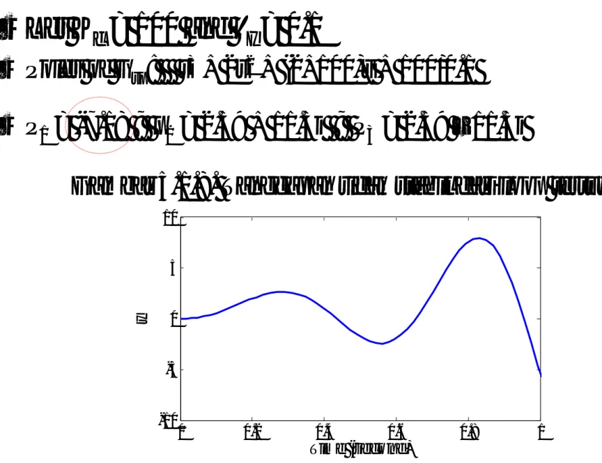
Gambar 5.1.8. Tanggapan tidak stabil dari loop tertutup

(16)

Example 5.1.2 (Continued)

0

5

10

15

20

25

30

35

40

0

0.2

0.4

0.6

0.8

1

1.2

1.4

1.6

1.8

y

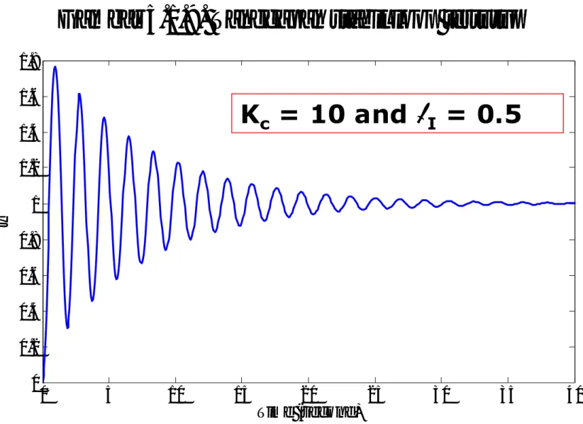
Gambar 5.1.9. Tanggapan stabil loop tertutup

(17)

5.2 The Characteristic Equation

)

(

1

)

(

1

)

(

d

s

G

G

G

G

G

s

y

G

G

G

G

G

G

G

s

y

m

c

f

p

d

sp

m

c

f

p

c

f

p

+

+

+

=

)

(

)

(

)

(

)

(

)

(

s

G

s

y

s

G

s

d

s

y

=

sp

sp

+

load

The closed loop response of FBC :

The characteristic equation :

1 + G

p

G

f

G

c

G

m

= 0

(18)

Let p

1

, p

2

, …, p

n

be the n roots of the

Characteristic Equation

1 + G

p

G

f

G

c

G

m

= (s – p

1

) (s – p

2

) … (s – p

n

)

Stability criterion of a closed loop system

A FBC system is stable if all the roots of its

characteristic equation have negative real

part (i.e. are to the left of the imaginary axis)

(19)

Example 5.2.1: Stability analysis of FBC based

on characteristic equation

c

c

m

f

p

G

G

G

K

s

G

=

=

=

=

1

1

1

10

( )( )( )

1

1

0

1

10

1

1

=

+

=

+

p

f

c

m

K

c

s

G

G

G

G

Again, consider Ex. 5.1.1

characteristic equation:

Which has the root: p = 1 – 10K

c

∴ The system is stable IF p < 0

10

1

>

c

K

5.2 Persamaan Karakteristik

(20)

⎟⎟

⎜⎜

+

=

=

=

+

+

=

s

K

G

G

G

s

s

G

I

c

c

m

f

p

τ

1

1

;

1

;

1

;

2

2

1

2

( )( )

1

1

0

2

2

1

1

1

2

⎟⎟

=

⎜⎜

+

+

+

+

=

+

s

K

s

K

s

s

G

G

G

G

I

c

I

c

m

c

f

p

τ

τ

Again, consider Ex. 5.1.2

characteristic equation:

Which has three roots,

Æ

K

c

and

τ

I

affect the value of roots

(i.e. positive or negative)

(

2

)

0

2

2

3

+

+

+

+

=

I

c

c

K

s

K

s

s

τ

(21)

5.3 Kestabilan Berdasarkan Ultimate

Response

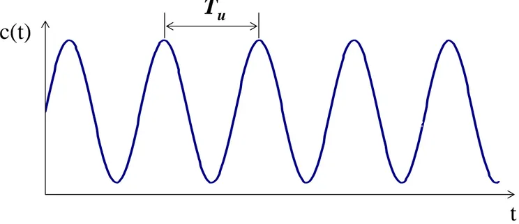
Pada bagian ini kita akan membahas batasan kestabilan berdasarkan respon

kritis (ultimate response).

Ingat kembali! Respon stabil jika akar-akar denominator pada FT adalah

negatif (di sebelah kiri sumbu imaginer pada bidang kompleks).

Metode Substitusi Langsung

Metode

ini

sangat

mudah

untuk

mencari

parameter-parameter

pengendalian yang mana dapat menghasilkan respon stabil.

Jika pers. karakteristik mempunyai satu atau dua akar yang terletak tepat

pada sumbu imaginer, maka menghasilkan respon kritis (osilasi terjaga).

Ultimate Gain, K

cu

: gain pengendali yang mana dapat menghasilkan

(22)

Gambar 5.3.1 respon loop tertutup dengan K

c

= K

cu

( )

t

=

(

ω

t

+

θ

)

C

sin

u

u

u

T

ω

π

2

=

-1.1-1 -0.9 -0.8 -0.7 -0.6 -0.5 -0.4 -0.3 -0.2 -0.10 0.1 0.2 0.3 0.4 0.5 0.6 0.7 0.8 0.91 1.1 0 5 10 15 20 25 30

c(t)

T

u

t

Ultimate period

ω

u

= ultimate frequency

(23)

( ) ( ) ( ) ( )

0

1

+

G

p

s

G

f

s

G

c

s

G

m

s

=

Persamaan Karakteristik loop tertutup: denominator dari FT loop tertutup

... (5.3.1)

Substitusi langsung: s = i

ω

u

Bagian real = 0

Bagian imaginer = 0

Penyelesaian secara simultan

menghasilkan ultimate gain, K

cu

Contoh 5.3.1: mencari K

cu

dan

ω

u

untuk pengendali suhu pada HE

Steam

Process fluid

T

i

(t),

o

C

Condensate

TC

W(t), kg/s

T

o

(t),

o

C

TT

T

o set

(t),

o

C

W

s

(t), kg/s

M(t), %CO

C(t), %TO

(24)

( )

TO

CO

K

s

G

c

c

%

%

=

( )

CO

s

kg

s

s

G

v

%

/

1

3

016

.

0

+

=

( )

s

kg

C

s

s

G

o

S

/

1

30

50

+

=

( )

C

TO

s

s

G

m

%

o

1

10

1

+

=

+

W(s)

+

C(s), %TO

M(s)

E(s)

R(s) +

G

c

(s)

G

m

(s)

G

v

(s)

K

sp

%TO

%CO

G

S

(s)

G

w

(s)

W

s

(s)

kg/s

T

o

(t),

o

C

T

o

set

(t),

o

C

%TO

kg/s

P Control

dimana:

(25)

( ) ( ) ( ) ( )

0

1

+

G

m

s

G

S

s

G

v

s

G

c

s

=

Persamaan Karakteristik loop tertutup:

0

80

.

0

1

43

420

900

s

3

+

s

2

+

s

+

+

K

c

=

0

1

3

016

.

0

1

30

50

1

10

1

1

=

+

+

+

+

K

c

s

s

s

Penyusunan kembali persamaan di atas diperoleh:

(

10

s

+

1

)(

30

s

+

1

)(

3

s

+

1

)

+

0

.

80

K

c

=

0

Substitusi s = i

ω

u

pada K

c

= K

cu

:

0

80

.

0

1

43

420

900

i

3

ω

u

3

+

i

2

ω

u

2

+

i

ω

u

+

+

K

c

=

(

420

ω

u

2

+

1

+

0

.

80

K

c

) (

+

i

900

ω

u

3

+

43

ω

u

)

=

0

+

i

0

i

2

= –1

(26)

0

80

.

0

1

420

2

+

+

=

ω

u

K

c

0

43

900

3

+

=

ω

u

ω

u

Kedua pers. di atas diselesaikan secara simultan, menghasilkan:

ω

u

= 0

K

cu

= –1.25 %CO/TO

ω

u

= 0.2186 rad/sec

K

cu

= 23.8 %CO/TO

relevant

Jadi diperoleh ultimate period:

sec

7

.

28

2186

.

0

2

=

=

π

u

T

Jika diinginkan

respon STABIL,

maka K

c

< K

cu

(27)

0

50

100

150

200

-0.5

0

0.5

1

T

e

m

p

er

at

u

re [

d

eg

C

]

Time [sec]

0

50

100

150

200

-0.2

-0.1

0

S

team

[

k

g

/sec]

Time [sec]

Gambar 5.3.3. Tanggapan kritis pengendali suhu terhadap perubahan

satu unit set point dengan fungsi tahap (Contoh 5.3.1)

Kc = Kcu = 23.8

(28)

0

50

100

150

200

-1

0

1

2

T

e

mp

er

at

u

re [

d

eg

C

]

Time [sec]

0

50

100

150

200

-0.2

-0.1

0

S

team [

k

g

/sec]

Gambar 5.3.4. Tanggapan stabil pengendali suhu terhadap perubahan

satu unit set point dengan fungsi tahap (Contoh 5.3.1)

(29)

0

50

100

150

200

-5

0

5

T

e

m

p

er

at

u

re [

d

eg

C

]

Time [sec]

0

50

100

150

200

-1

-0.5

0

0.5

S

team

[

k

g

/sec]

Time [sec]

5.3 Kestabilan Berdasarkan Ultimate Response

Gambar 5.3.5. Tanggapan tidak stabil pengendali suhu terhadap

perubahan satu unit set point dengan fungsi tahap (Contoh 5.3.1)

(30)

• Does not require calculation of actual

values of the roots of the characteristic

equation.

• But, it only requires that we know if any

root is to the right of imaginary axis

• Make a conclusion as to the stability of

closed loop system quickly without

(31)

Expand the characteristic eq. into the following

polynomial form

1 + G

p

G

f

G

c

G

m

a

o

s

n

+

a

1

s

n-1

+ … +

a

n-1

s +

a

n

= 0

Let

a

o

be positive, if it is negative, multiply both

sides of equation by −1.

First Test: If any of coefficients

a

1

,

a

2

, … ,

a

n-1

,

a

n

is

negative; there is at least one root of the characteristic

eq. which has positive real part Æ UNSTABLE

Second Test: If all coefficients

a

1

,

a

2

, … ,

a

n-1

,

a

n

are

positive; Then, from the 1

st

test we cannot conclude

anything about the location of the roots. Form the

following array (known as Routh array):

(32)

Routh Array

.

.

W

2

W

1

n+1

.

.

.

.

.

A

3

C

2

C

1

5

.

B

3

B

2

B

1

4

.

A

3

A

2

A

1

3

a

7

a

5

a

3

a

1

2

a

6

a

4

a

2

a

0

1

Row

(33)

Where

1

3

0

2

1

1

a

a

a

a

a

A

=

1

5

0

4

1

2

a

a

a

a

a

A

=

1

7

0

6

1

3

a

a

a

a

a

A

=

1

2

1

3

1

1

A

A

a

a

A

B

=

1

3

1

5

1

2

A

A

a

a

A

B

=

1

2

1

2

1

1

B

B

A

A

B

C

=

1

3

1

3

1

2

B

B

A

A

B

C

=

. . .

. . .

. . .

etc

.

(34)

Examine the elements of the first

column of the array above

• If any of these elements is negative, we have at

least one root to the right of the imaginary axis

and the system is UNSTABLE

• The number of sign changes in the elements of

the first column is equal to the number of roots

to the right of the imaginary axis

a

0

a

1

A

1

B

1

C

1

. . . W

1

∴ A system is STABLE IF all the elements in the

first column of the Routh Array are POSITIVE

(35)

Example 5.4.1: Stability Analysis with the

Routh-Hurwitz Criterion

(

2

)

0

2

2

3

+

+

+

+

=

I

c

c

K

s

K

s

s

τ

I

c

K

τ

Consider FBC system in Ex. 5.1.2, Its Characteristic eq. is

(

)

2

2

2

I

c

c

K

K

τ

+

I

c

K

τ

Routh array is:

Row

1

st

Column

1

2

3

4

1

2

2 + K

c

0

(36)

Example 5.4.1 (Continued)

(

)

+

I

c

I

c

c

K

K

K

τ

τ

,

2

2

2

,

2

,

1

The elements of the first column are:

Third element can be positive or negative

depending on the values of K

c

and

τ

I

The system is STABLE if K

c

and

τ

I

satisfy

the condition:

(

)

c

c

K

K

τ

>

+

2

2

(37)

Example 5.4.2: Critical stability Conditions for FBC

Return to Ex.5.4.1, and Let

τ

I

= 0.1

(

)

2

10

2

2

+

K

c

K

c

3

rd

element becomes:

IF K

c

= 0.5 Æ third element = 0 Æ critical condition,

two roots on imaginary axis (pure

imaginary) Æ ± j(1.58)

Æ sustained sinusoidal response

IF K

c

< 0.5 Æ third element is positive Æ STABLE

IF K

c

> 0.5 Æ third element is negative Æ UNSTABLE

(38)

Gambar 5.4.1. Tanggapan kritis dari sistem terkendali terhadap

perubahan satu unit set point dengan fungsi tahap (Contoh 5.4.1)

Kc = 0.5 ; thoi = 0.1

0

5

10

15

0

0.5

1

1.5

2

CV

Time [sec]

0

5

10

15

-2

0

2

4

6

MV

Time [sec]

(39)

5.3 Kestabilan Berdasarkan Ultimate Response

Gambar 5.4.2. Tanggapan stabil dari sistem terkendali terhadap

perubahan satu unit set point dengan fungsi tahap (Contoh 5.4.1)

Kc = 0.1 ; thoi = 0.1

0

5

10

15

0

0.5

1

1.5

CV

Time [sec]

0

5

10

15

0

1

2

3

MV

Time [sec]

(40)

Gambar 5.4.3. Tanggapan tidak stabil dari sistem terkendali terhadap

perubahan satu unit set point dengan fungsi tahap (Contoh 5.4.1)

Kc = 1 ; thoi = 0.1

0

5

10

15

-20

-10

0

10

20

CV

Time [sec]

0

5

10

15

-200

-100

0

100

MV

(41)

5.5 Root-Locus Analysis

• Root Locus is a graphical technique that

consists of graphing the roots of the

characteristic equation

• The resulting graph allows to see whether

a root crosses the imaginary axis to the

right hand side of the s-plane

(42)

Example 5.5.1

: Root locus for a Reactor with P Control

R

A

Flow rate = m

Flow rate = F – m

Flow rate = F

Concentration in C = y

Reactions:

A + R Æ B

B + R Æ C

C + R Æ D

D + R Æ E

The control objective is to keep the concentration of

the desired product C as close as possible to its set

point by manipulating the flow rate of A

(43)

Example 5.5.1: (Continued)

(

)

(

1

.

45

)(

2

.

85

) (

4

.

35

)

25

.

2

98

.

2

)

(

)

(

)

(

2

+

+

+

+

=

=

s

s

s

s

s

m

s

y

s

G

p

TF of the process:

(

)

(

1

.

45

)(

2

.

85

) (

4

.

35

)

0

25

.

2

98

.

2

1

2

=

+

+

+

+

+

K

c

s

s

s

s

Implementation of P Control with G

c

(s) = K

c ,

and

Assume that G

m

= G

f

= 1, we have the following

characteristic equation:

S

4

+ 11.5 s

3

+ 47.49 s

2

+ (2.98K

c

+ 83.0633)s

+ (6.705K

c

+ 51.2327) = 0

(44)

Roots of the characteristic equation

(for ex. 5.5.1)

−9.85

+0.30

− 5.70 j

+0.30

+ 5.70 j

−2.25

100

−8.49

−0.38 − 4.48 j

−0.38 + 4.48 j

−2.24

50

−7.14

−1.06 − 3.23 j

−1.06 + 3.23 j

−2.23

20

−5.77

−1.76 − 1.88 j

−1.76 + 1.88 j

−2.20

5

−4.89

−2.34 − 0.82 j

−2.34 + 0.82 j

−1.92

1

−2.85

−2.85

−2.85

− 1.45

0

p

4

p

3

p

2

p

1

K

c

(45)

Gambar 5.5.1. Root-Locus of the reactor in Ex. 5.5.1

-20

-15

-10

-5

0

5

10

15

-20

-15

-10

-5

0

5

10

15

20

Root Locus

Real Axis

Im

agi

nar

y A

xi

s

(46)

Gambar 5.5.2. Tanggapan stabil loop terkendali terhadap

perubahan satu unit set-point (Ex. 5.5.1)

Kc = 50

Kc = 20

Kc = 5

Kc = 1

0

2

4

6

8

10

12

14

16

18

20

0

0.5

1

1.5

Time (Sec)

y

Offset

New set-point

(47)

0

2

4

6

8

10

12

14

16

18

20

0

0.5

1

1.5

2

Time (Sec)

y

Critical condition

Kc = 75

5.5 Analisis Kestabilan dengan Root-Locus

Gambar 5.5.3. Tanggapan kritis dari loop terkendali

terhadap perubahan satu unit set-point (Ex. 5.5.1)

(48)

0

2

4

6

8

10

12

14

16

18

20

-300

-200

-100

0

100

200

300

y

Kc = 100

Gambar 5.5.4. Tanggapan tak-stabil dari loop terkendali

terhadap perubahan satu unit set-point (Ex. 5.5.1)

Gambar

Gambar 5.1.1. Bounded Input Input m(t) timeUpper LimitLower Limitsinusoidalstep
Gambar 5.1.2. Tanggapan (response) stabil dan tidak stabil y timeDesired valueStableUnstableUnstable
Gambar 5.1.3. Complex Plane
Gambar 5.1.4. Tanggapan sistem tak-terkendali terhadap perubahan satu unit gangguan dengan fungsi tahap
+7

Referensi