Orientation of MOMS-02
r
D2 and MOMS-2P
r
PRIRODA
imagery
1H. Ebner
a,2, W. Kornus
b, T. Ohlhof
c,), E. Putz
da ( )
Chair for Photogrammetry and Remote Sensing, Technische UniÕersitat Munchen TUM , D-80290 Munich, Germany¨ ¨
b ( )
German Aerospace Center DLR e.V., Institute for Optoelectronics, PO Box 1116, D-82230 Wessling, Germany
c ( )
Elektroniksystem-und Logistik ESG , System DeÕelopment, Reconnaissance and Remote Sensing Systems, PO Box 800 569, D-81605 Munich, Germany
d ( )
Starkstrom-Anlagen-Gesellschaft SAG , Landshuter Str. 65, D-84030 Ergolding, .Germany
Received 13 June 1998; accepted 15 February 1999 Dedicated to Dr.-Ing. Otto Hofmann
Abstract
This paper deals with the orientation of three-line imagery which has been taken during the MOMS-02rD2 experiment in spring 1993, and during the MOMS-2PrPRIRODA mission since April 1996. The reconstruction of the image orientation is based on a combined adjustment of the complete image, ground control, orbit and attitude information. The combined adjustment makes use of the orientation point approach or the orbital constraints approach. In the second case, the bundle adjustment algorithm is supplemented by a rigorous dynamical modeling of the spacecraft motion. The results of the combined adjustment using MOMS-02rD2 imagery and control information of orbit a75b are presented. Based on the
Ž .
orientation point approach an empirical height accuracy of up to 4 m 0.3 pixel is obtained. In planimetry the empirical
Ž . Ž .
accuracy is limited to about 10 m 0.7 pixel , since the ground control points GCP and check points could not be identified in the imagery with the required accuracy. Computer simulations on MOMS-2PrPRIRODA image orientation based on realistic input information have shown that good accuracies of the estimated exterior orientation parameters and object point coordinates can be obtained either with a single strip and a few precise GCP or even without ground control information, if a
Ž .
block of several overlapping and crossing strips with high geometric strength qf60% is adjusted. q1999 Elsevier Science B.V. All rights reserved.
Keywords: image orientation; Three-line CCD cameras; Bundle block adjustment; MOMS; Orbital constraints
)Corresponding author. Fax: q49-89-9216-2732; E-mail:
1
Updated version of a paper presented at the ISPRS Congress in Vienna, 1996.
2
Tel.: q49-89-2892-2671; Fax: q49-89-280-9573; E-mail: [email protected].
1. Introduction
During the 2nd German Spacelab mission D2, successfully flown in AprilrMay 1993, the Modular Optoelectronic Multispectral Stereo Scanner MOMS-02 acquired digital high resolution, along track, three-fold stereoscopic and multispectral imagery of the earth surface. The MOMS-02rD2 experiment was the first use of a three-line camera in space.
0924-2716r99r$ - see front matterq1999 Elsevier Science B.V. All rights reserved.
Ž .
Although the results of this experiment are remark-able, the high accuracy potential of the MOMS-02 sensor could not be exhausted due to several prob-lems. These problems, however, have been an impor-tant experience in the preparation phase of the MOMS-2PrPRIRODA mission from the Russian space station MIR, launched in April 1996.
The photogrammetric processing of the MOMS-02rD2 and MOMS-2PrPRIRODA data is con-ducted by several German university institutes and the DLR. The major aim is to realize the entire photogrammetric processing chain, which starts with radiometrically corrected image data and ends up
Ž .
with digital terrain models DTM , orthoimage maps
Ž .
and vector data for geo-information-systems GIS . Within the science team the Chair for Photogramme-try and Remote Sensing of the TUM is responsible for the reconstruction of the exterior orientation by combined adjustment and the semi-automatic extrac-tion of linear objects for updating the German GIS ATKIS-DLM25.
After a description of the two camera experiments MOMS-02rD2 and MOMS-2PrPRIRODA and the combined bundle adjustment concept, the results of the adjustment using MOMS-02rD2 imagery of or-bita75b are presented and assessed. Then the results of computer simulations on MOMS-2PrPRIRODA image orientation are discussed. Finally the experi-ences are summarized and an outlook is given.
2. MOMS-02rrrrrD2 and MOMS-2PrrrrrPRIRODA camera experiments
2.1. MOMS-02rD2 experiment
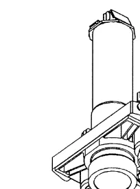
The optical system of MOMS-02 consists of a
Ž .
stereo module and a multispectral module Fig. 1 . In seven different imaging modes certain combinations of the panchromatic stereo and the multispectral channels can be selected. The three lenses of the
Ž
stereo module with 1 CCD sensor array Fairchild
.
191 each provide three-fold along track stereo scan-ning with different ground resolutions. The nadir
Ž .
[image:2.595.343.445.51.188.2]looking CCD array 4.5 m ground pixel size com-prises two arrays with 6000 sensor elements each, which are optically combined to one array with 9000 sensor elements. The other CCD arrays of the stereo
Fig. 1. Optical system of the MOMS-02 camera. The two inclined
Ž"21.98. stereo lenses are depicted in the background. In the foreground, the high resolution lens is visible, arranged between two lenses for multispectral data recording.
Ž
module consist of 6000 sensor elements 13.5 m
.
ground pixel size . In stereo imaging mode 1 8304 sensor elements of the HR channel and 2976 sensor elements of the stereo channels are active.
In the course of the 10 day lasting D2 mission, 48 data takes with a data volume of 300 GB were recorded during 4.5 h, covering an area of about 7 Mio. km2. Due to the orbital inclination of 28.58 industrial countries in Europe and North America have not been imaged. More detailed information about the MOMS-02rD2 camera experiment is given
Ž .
by Ackermann et al. 1989 , Seige and Meissner
Ž1993 and Fritsch 1995 .. Ž .
To demonstrate the combined adjustment of im-age, orbit and attitude data, one imaging sequence
Žmode 1 with 32 120 rows covering 37. =430 km2
Ž .
in Northern Australia orbita75b has been chosen
Žsee Section 4 ..
2.2. MOMS-2PrPRIRODA experiment
The MOMS-2P camera is part of the PRIRODA module, which is equipped with several remote sens-ing instruments. Overall goals of the PRIRODA
ŽRuss. nature project are to investigate nature pro-.
cesses and to further develop remote sensing
meth-Ž .
ods Armand and Tishchenko, 1995 .
Table 1
Main parameters of MOMS-02rD2 and MOMS-2PrPRIRODA
MOMS-02rD2 MOMS-2PrPRIRODA
Camera carrier Space shuttle MIR space station
Mission duration 10 days at least 18 months
Data storage HDT recorder onboard mass memory and
telemetry to ground stations
w x
Orbital height km 296 400
w x
Orbital inclination 8 28.5 51.6
w x
Ground pixel size nadirrstereo m 4.5r13.5 6.0r18.0
w x
Swath width nadirrstereo km 37r78 50r105
Geometric camera calibration laboratory laboratory, inflight
Orbit information TDRSS tracking GPS
Attitude information IMU IMU, star sensor
countries in Europe and North America. Due to several problems, only a few MOMS-2PrPRIRODA images were acquired between September 1996 and April 1997. Since January 1998 MOMS-2P is operat-ing again.
The camera geometry including the alignment of the MOMS-2P camera axes has been determined not only by calibration in the laboratory, but also by
Ž .
inflight calibration Kornus and Lehner, 1997 . A special navigation package MOMSNAV con-sisting of high precision GPS and Inertial
Measure-Ž .
ment Unit IMU ensures precise orbit and attitude data, synchronized with the MOMS-2PrPRIRODA imagery to 0.1 ms. Based on GPS observations during a time interval of ca. 5 min and a sophisti-cated short arc modelling, the MIR orbit has been determined with 5 m absolute accuracy. The Astro 1 star sensor, which is mounted on the QUANT mod-ule of the MIR station provides 10Y. attitude accu-racy. The alignment, however, between the QUANT and the PRIRODA module is known only in the order of 200Y.
3. Combined bundle adjustment
The photogrammetric point determination is based on the principle of bundle adjustment and comprises the determination of object points and the reconstruc-tion of the exterior orientareconstruc-tion of the three-line im-ages. It represents a central task within the
pho-togrammetric processing chain on which all subse-quent products are based.
The collinearity equations
c
ˆ
usu x , x
Ž
ˆ ˆ
Ž .
t ,uŽ .
t.
Ž .
1formulate the relationship between the observed
im-Ž .T
age coordinates us u ,ux y , the unknown object
ˆ ˆ ˆ
TŽ .
point coordinates x
ˆ
s X,Y, Z of a point P and the unknown parameters of exterior orientation xˆ
csˆ
cˆ
cˆ
c Tˆ
TŽX ,Y , Z . and usŽv,w,k
ˆ ˆ ˆ
. , respectively, of the image I taken at time t. The orientation anglesj v,w and k have to be chosen in such a way that singular-ities are avoided. In space photogrammetry the three Euler angles z, h and u, which are related to the spacecraft motion along the trajectory, are well suited in conjunction with a geocentric object coordinate system.3.1. Orientation point approach
In general, the mathematical model for the recon-struction of the exterior orientation should use six unknown parameters for each three-line image I . Inj practice, however, there is not enough information to determine such a large number of unknowns. In the orientation point approach, the exterior orientation parameters are estimated only for so-called orienta-tion points or orientaorienta-tion images I , which are intro-k
functions of the parameters at the neighboring
orien-Ž .
tation points Ebner et al., 1994 . While this ap-proach reduces the number of unknown exterior orientation parameters to a reasonable amount, its inherent disadvantage is that the estimated position parameters are not associated with a physical model of the spacecraft trajectory.
3.2. Orbital constraints approach
To overcome this drawback, the bundle adjust-ment algorithm is suppleadjust-mented by a rigorous dy-namical modeling of the spacecraft motion to take orbital constraints into account. The camera position
cŽ .
parameters x
ˆ
t which have been estimated so farat certain time intervals, are now expressed by the six parameters of the epoch state vector y
ˆ
0 and additional force model parameters p:ˆ
xc
Ž .
t sxc t , y , pŽ .
2ˆ
ˆ
Ž
ˆ ˆ
0.
The force model parameters p may comprise, e.g., the drag coefficient. For the epoch state vector observation equations
y0sy0
Ž
yˆ
0.
Ž .
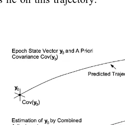
3 [image:4.595.90.219.467.596.2]are introduced, where the observations y are taken0 from the results of the previous orbit determination. Fig. 2 demonstrates the orbital constraints ap-proach, which exploits the fact that the spacecraft proceeds along an orbit trajectory and all camera positions lie on this trajectory.
Fig. 2. Orbital constraint approach for the reconstruction of the
Ž .
exterior orientation of three-line images Ohlhof et al., 1994 .
Compared to the orientation point approach the orbital constraints approach has essential advantages, which can be summarized as follows:
Ø Full utilization of the information content of the tracking data in a statistically consistent way.
Ø A reduced number of unknown parameters.
Ø Accuracy improvements for the photogrammetric results as well as the epoch state vector.
Statistically, the resulting estimation procedure is equivalent to a combined orbit determination and bundle adjustment from tracking data and three-line image data.
Due to the lack of a dynamical model describing the camera’s attitude behavior during an imaging sequence, it is not possible to introduce attitude constraints into the bundle adjustment in a similar way as the orbital constraints. To this end, the concept of orientation points is maintained for the camera’s attitude. The attitude
ˆ
ˆ
ˆ
u
Ž .
t suŽ
t ,Q.
Ž .
4 of the camera can be represented by the attitude vector Q at selected orientation points. Based onŽ . Ž . Ž .
Eqs. 1 , 2 and 4 , the image coordinates may finally be written as
c
ˆ
ˆ
usu x , x
Ž
ˆ ˆ
Ž .
t ,uŽ .
t.
su t , x , y , p,Ž
ˆ ˆ ˆ
0 Q.
Ž .
5 For the incorporation of preprocessed attitude data corresponding observation equations are formulated. Systematic errors of the attitude observations are modeled through additional estimation parameters. By limitation to constant and time-dependent linear terms which describe the main effects, six additional parameters, namely a bias and a drift parameter for each attitude angle, are used for each orbital arcŽsimaging sequence ..
The observation equations for the attitude parame-ters, which are introduced at selected orientation points, are given by
ˆ ˆ
QsQ Q
Ž
,b.
,Ž .
6ˆ
whereb denotes the unknown bias and drift parame-ters.
The mathematical model of the orbital constraints
Ž .
approach is described in detail in Ohlhof 1996 and
Ž .
4. Practical results of MOMS-02rrrrrD2 image ori-entation
This section describes the orientation of MOMS-02rD2 imagery based on the orientation point ap-proach. Four image scenes a15 to a18 of the D2
Ž .
orbit a75b nomenclature of DARA, 1994 were selected, covering an approximately 37=430 km wide area in Northern Australia. Besides several tie points, calibration data, navigation data and 64 ground control and check points are considered as additional information in a combined adjustment.
During the last 2 years the Australian MOMS-02rD2 data set was also evaluated by other research
Ž .
groups in Zurich Baltsavias and Stallmann, 1996 ,
Ž . Ž
Melbourne Fraser and Shao, 1996 , Munich Dorrer
.
et al., 1995 and Glasgow. The four groups used different input data sets and different mathematical models. Most of the point determination results, however, fit in quite well with the results described in this paper.
4.1. Input data
The image coordinates of tie points were derived automatically by a modified region-growing
match-Ž .
ing algorithm Otto and Chau, 1989 , which was
Ž
applied successfully in the past to SPOT Heipke and
. Ž
Kornus, 1991 and airborne MEOSS imagery Heipke
.
et al., 1996 . From this information a sparse and a dense subset of regularly distributed points were selected to be fed into the adjustment. According to experiences of the former evaluations, a standard deviation of 0.3 pixel for the image coordinates was assumed.
The calibration data were provided by the
Ger-Ž .
man aerospace company DASA former MBB , the
Ž .
manufacturer of MOMS-02 DASA, 1994 . Correc-tion tables describe deviaCorrec-tions of certain CCD pixels
Ž500 pixel distance from their nominal positions in.
the image plane. The functional model of the interior orientation employs 9 parameters per lens or per
Ž .
channel, as described in Ebner et al., 1994 . A 10th parameter, modelling a second order sensor curva-ture, was added, since band-to-band registration of the first MOMS-2PrPRIRODA imagery yielded sys-tematic non-linear deviations from the calibration
Ž .
data of the multispectral channels Kornus, 1996 . In
order to compensate for possible deviations of the stereo channels, the lab-calibrated parameters of the interior orientation were introduced with low weight into the adjustment allowing for the simultaneous estimation of deviations, at least to some extent.
The naÕigation data were provided by NASA and
Ž .
processed by Geo-Forschungs-Zentrum GFZ Pots-dam. The orbit positions were compiled from TDRSS Doppler measurements, which were fed as observa-tions into the orbit determination software of GFZ
Ž .
Potsdam Braun and Reigber, 1994 , yielding a rela-tive orbit accuracy of 3 m and an absolute accuracy
Ž . Ž . Ž .
of 14 m radial , 32 m lateral and 31 m tangential . The gyro data were already preprocessed by NASA and provided as a time series of Euler angles at 1 s time interval with a relative accuracy of 20Y. Since the alignment between the MOMS camera axes and the gyro axes was not calibrated, there is no absolute pointing knowledge. Both Euler angles and orbit positions were transformed into a local topocentric coordinate system with fundamental point at fs 21830X
S, ls136800X
W, hs300.0 m. Based on ap-proximation tests 8 orientation points were selected, having a distance of 4612 rows between each other.
( )
Seventy-seven ground control points GCP were measured by Melbourne University using differential
Ž .
GPS Fraser et al., 1996 . The points are located in a 37=100 km wide flat desert area covered by image scene a17. Most of the targets represent road junc-tions or dams of artificial water basins, which could be identified in the imagery with about 1 pixel precision. At ETH Zurich 68 GCP were measured in
Ž .
the channel ST6 imagery forward and
automati-Ž .
cally transferred to channel ST7 aft . At DLR 49 of
Ž .
these points were transferred to channel HR5 nadir from both ST6 and ST7 imagery. From the differ-ences in HR5 a standard deviation of 0.4 pixel for the GCP image coordinates was derived. For the GCP object coordinates ss1 m was chosen in
Ž .
height and ss13.5 m 1 pixel in planimetry, due to the identification uncertainties.
4.2. Results
Fig. 3. Configuration of control and check points.
recordings in the order of 1.6 s. Further adjustment runs using all GCP led to the rejection of 4 GCP due to large planimetric residuals. From the remaining 64
Ž .
GCP root-mean-square rms residuals of 9 m in X, 8 m in Y and 0.1 m in Z were obtained. The Z component is quite small due to the high weighting
Ž .
of the GCP Z coordinates ss1 m compared to the weighting of the corresponding image coordinates
Žss0.4 pixel . The planimetric residuals of nearly.
10 m reflect the identification uncertainty mentioned above.
In a series of adjustment runs using subsets of 4, 10 and 20 GCP, empirical accuracies were derived from the remaining 44 points, which served as
inde-Ž .
pendent check points see Fig. 3 .
The Tables 2 and 3 contain the empirical
accura-Ž .
cies rms values computed for the different GCP configurations and sets of tie points using all
naviga-Ž . Ž .
[image:6.595.286.504.70.134.2]tion data Table 2 and orbit data only Table 3 . The comparison between Tables 2 and 3 shows no significant differences in the results, indicating that attitude information is not required. From Tables 2 and 3 it can be seen that the results are only slightly improved if 1000 instead of 100 tie points are used. Despite of the given uncertainties, a height accuracy of up to 4.1 m is obtained, corresponding to 0.3 of the ground pixel size of the oblique looking channels
Table 2
Ž .
Empirical accuracies rms values ´ using all navigation data 1000 tie points 100 tie points
4 GCP 10 GCP 20 GCP 4 GCP 10 GCP 20 GCP w x
´X m 11.6 10.8 10.3 11.6 11.0 10.1 w x
´Y m 12.8 9.3 8.9 12.8 9.7 9.4 w x
[image:6.595.339.453.466.579.2]´Z m 4.1 4.6 4.3 5.3 4.9 4.7
Table 3
Ž .
Empirical accuracies rms values ´ using orbit data only 1000 tie points 100 tie points
4 GCP 10 GCP 20 GCP 4 GCP 10 GCP 20 GCP w x
´X m 10.8 10.5 10.0 11.4 10.6 9.5 w x
´Y m 12.6 9.8 9.3 13.9 10.0 9.4 w x
´Z m 4.1 4.5 4.3 5.2 4.6 4.6
Ž13.5 m . The planimetric accuracy potential of.
MOMS-02rD2 is not verified, since the GCP and check points could not be identified in the imagery with the required accuracy.
5. Computer simulations on MOMS-2Prrrrr
PRIRODA image orientation
A series of computer simulations have been car-ried out to analyze the effect of certain parameters on the accuracy of MOMS-2P image orientation, especially the effect of block configuration and con-trol information.
5.1. Input parameters
5.1.1. Block configurations
The computer simulations were performed for three different block configurations:
Ø Single strip
Ø Block of six strips with qs20% side overlapq two crossing strips
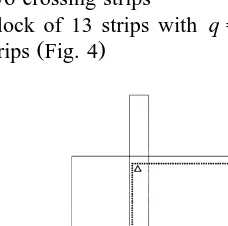
Ø Block of 13 strips with qs60%qtwo crossing
Ž .
strips Fig. 4
[image:6.595.48.262.554.618.2]The strip length was chosen to four baselengths
Ž640 km . This results in the fact that points at the.
beginning and the end of the single strip are pro-jected into two images only, whereas each point in the central part of the strip is projected into three images. The strip width amounts to 50 km. The
2 Ž
entire block covers 320=250 km without two-ray
. Ž
area , corresponding to the area of Catalonia 270=
2.
250 km , which was thought to be the most impor-tant test site of the MOMS-2P experiment.
5.1.2. Interior orientation parameters
All parameters of the interior orientation were introduced as error-free values.
5.1.3. Conjugate points
The object coordinate system is defined as topocentric Cartesian system XYZ with the positive direction of the X-axis parallel to the direction of flight. The object points are arranged in two different grids:
Case 1:DXs40.0 km,DYs20.0 km, Zs0.0 km.
Case 2: DXs2.0 km, DYs10.0 km, Zs0.0 km.
Consequently the single strip consists of 27 and the blocks contain 117 object points in the first case, whereas the single strip consists of 805 and the blocks contain 4025 object points in the second case. For each block configuration, the image coordinates of the object points were computed assuming a flight path with a constant altitude of 400 km and attitude values equal to zero.
In case 1 only a few conjugate points are included
Ž .
which can be measured high precisely ss0.1 pixel using a digital stereo comparator, whereas in case 2 additional tie points derived from digital image
Ž .
matching ss0.3 pixel are introduced. Thus, we have the following two cases for the image coordi-nates, which were treated as being uncorrelated:
Case 1: ss0.1 pixel for all image coordinates.
Case 2: ss0.3 pixel for all image coordinates,
Ž . Ž .
except for the 27 points strip and 117 points block of Case 1, respectively, having ss0.1 pixel.
5.1.4. Ground control information
The simulations have been carried out for two different configurations of ground control informa-tion:
Case a: no ground control.
Case b: 16 GCP with sXssYssZs1.0 m.
The 16 GCP are arranged in four groups of four points each, located at the corners of the at least three-ray area of the strip or the block. The standard deviations of the GCP’s image coordinates are as-sumed to 0.3 pixel.
5.1.5. Orbit and attitude obserÕations
For the orbit and attitude observations two differ-ent cases were investigated:
Ž .
Case A: error-free observations ss0 .
Case B: realistic orbit and attitude observations. ŽTable 4.
Case A defines the accuracy limit, whereas case B is the realistic one. In Table 4 the standard deviations describing the relative accuracy of the position pa-rameters are nearly zero, since all camera positions are constrained to lie on the orbit trajectory. The standard deviations describing the absolute accuracy are 5 m for the position and 2 cmrs for the velocity components of the epoch state vector. For each orientation point attitude observations were intro-duced with a relative accuracy of 10Y. Due to the poor alignment precision of the MOMS-2P camera with respect to the Astro 1 star sensor, no
observa-Table 4
Standard deviations of the observed position and attitude
parame-Ž .
ters –: no observation
Position Attitude
Y
Relative 0.1 m 10
Absolute position 5.0 m –
velocity 2 cmrs –
Absolute bias – –
Y
[image:7.595.287.502.549.617.2]tions for the attitude bias are assumed. The drift of the IMU gyros should not exceed 0.16Yrs during one MOMS-2P imaging sequence.
Based on experiences with MOMS-02rD2 data, the distance between the orientation points was
cho-Ž .
sen to 4940 rows ca. 90 km leading to nine orienta-tion points per strip.
5.2. Results
Ž .
For analysis, the rms values mX Yˆ ˆ planimetry
Ž .
andmZˆ height of the theoretical standard deviations sXˆ, sYˆ and sZˆ of all points within the dotted lines in Fig. 4 were calculated. Moreover, the rms values mzhuˆ ˆˆ of the theoretical standard deviations of the
ˆ
ˆ
estimated exterior orientation parameters z, h,
ˆ
u at the orientation points were computed. All accuracy figures were derived from the inverted normal equa-tion matrix. In case of a free adjustment the seven data parameters are determined by minimizing the trace of the covariance matrix of the estimated object point coordinates. So the free adjustment represents the interior accuracy of point determination. In Figs. 5–8 the rms values mX Yˆ ˆ and mZˆ are shown graphi-cally.First the results of the single strip and block
Ž .
adjustments with GCP are discussed Figs. 5 and 6 .
Ž .
Assuming error-free position and attitude data A ,
[image:8.595.338.447.50.212.2]the accuracy of point determination only depends on
Fig. 5. Rms values mX Yˆ ˆ for different block configurations with
Ž . Ž
GCP case b , observed position and attitude parameters cases A
. Ž .
and B and different number of object points cases 1 and 2 .
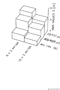
Fig. 6. Rms values mZˆ for different block configurations with
Ž . Ž
GCP case b , observed position and attitude parameters cases A
. Ž .
and B and different number of object points cases 1 and 2 .
the standard deviations of the image coordinates, the number of tie points and the geometric constellation of the ray intersections. The rms values are 1.1 m in planimetry and 3.5 m in height for the single strip. The planimetric and height accuracies decrease only moderatly, if the position and attitude data are
intro-Ž .
duced with realistic standard deviations case B ,
Ž .
[image:8.595.344.447.418.567.2]even with a small number of tie points case 2 . Using the equal number of GCP the accuracies improve by factor 1.4 for the qs20% blocks and by
Fig. 7. Rms valuesmX Yˆ ˆfor different block configurations without
Ž .
ground control case a , observed position and attitude parameters
Žcases A and B and different number of object points cases 1. Ž .
[image:8.595.102.211.422.588.2]Fig. 8. Rms valuesmZˆ for different block configurations without
Ž .
ground control case a , observed position and attitude parameters
Žcases A and B and different number of object points cases 1. Ž .
and 2 .
factor 1.8 for the qs60% blocks compared to the single strip, due to the increasing block strength. The blocks with qs60% and two additional crossing strips provide excellent rms values of about mX Yˆ ˆs 0.9 m, mZˆs2.5 m and mzhuˆ ˆˆ s1.6Y, respectively, in case 2.
From Figs. 5 and 6 it can be also seen that the number of tie points has only little influence on the rms values for the blocks. Even a small number of 117 points provides high accuracies in planimetry and in height.
In the following the adjustment results without
Ž .
GCP are analyzed Figs. 7 and 8 . The single strip leads to an undetermined configuration because no observations are available for attitude bias, and other observations are not able to compensate for that. If a block with qs20% and two crossing strips is ad-justed, all angles are determined due to the absolute position data, which were introduced for each strip of the block. A comparison of Figs. 7 and 8 with Figs. 5 and 6 shows that the object points are less accurate, if no GCP are introduced at all. A high
Ž .
number of conjugate points case 2 , however, leads to improvements of factor 1.3 for mX Yˆ ˆ and mZˆ
Ž .
compared to a small number of points case 1 . The best accuracies without ground control are achieved using observed position and attitude parameters for blocks with 13q2 strips and 4025 tie points, where
the rms values amount to mX Yˆ ˆs3.5 m, mZˆs4.6 m and mzhuˆ ˆˆ s2.3Y, respectively.
6. Summary and outlook
The reconstruction of the image orientation of the MOMS-02 camera is based on a combined adjust-ment of the complete image, ground control, orbit and attitude information. The combined adjustment makes use of the orientation point approach or the orbital constraints approach. In the second case, the bundle adjustment algorithm is supplemented by a rigorous dynamical modeling of the spacecraft mo-tion.
The results of the combined adjustment using MOMS-02rD2 imagery and control information of orbit a75b are presented. Based on the orientation point approach an empirical height accuracy of up to
Ž .
4 m 0.3 pixel is obtained. In planimetry the
empiri-Ž .
cal accuracy is limited to about 10 m 0.7 pixel , since the GCP and check points could not be identi-fied in the imagery with the required accuracy.
Computer simulations on MOMS-2PrPRIRODA image orientation based on realistic input informa-tion have shown that good accuracies of the esti-mated exterior orientation parameters and object point coordinates can be obtained either with a single strip and a few precise GCP or even without ground control information, if a block of several overlapping and crossing strips with high geometric strength
Žqf60% is adjusted..
In near future the evaluation of real MOMS-2PrPRIRODA data will show whether the models and findings of the simulations can be confirmed. First results based on nine image scenes of orbit T083C covering parts of Southern Germany and
Ž .
Austria have been presented by Kornus et al. 1998 .
Acknowledgements
The help of H. Froba, who performed most of the
¨
MOMS-2PrPRIRODA simulation runs, is gratefully acknowledged. The work presented in this paper is funded by grants 50 QS 9008 and 50 QM 9205 of
Ž .
References
Ackermann, F., Bodechtel, J., Lanzl, F., Meissner, D., Seige, P., Winkenbach, H., 1989. MOMS-02 — Ein multispektrales Stereo-Bildaufnahmesystem fur die zweite deutsche Spacelab-¨
Ž .
Mission D2. Geo-Information-Systems 2 3 , 5–11.
Armand, N.A., Tishchenko, Y.G., 1995. Russian PRIRODA pro-ject space experiments with MOMS-2P, Presented paper at the MOMS symposium, July 5–7, Cologne, Germany.
Baltsavias, E., Stallmann, D., 1996. Geometric potential of MOMS-02rD2 data for point positioning, DTM and orthoim-age generation. International Archives of Photogrammetry and
Ž .
Remote Sensing 31 4 , 110–116.
Braun, C.v., Reigber, C., 1994. Space shuttle orbit determination using empirical force modelling of attitude maneuvers for the German MOMS-02rD2 mission, Flight Mechanics and Esti-mation Theory Symposium, Goddard Space Flight Center, May 17–19, Greenbelt, USA.
DARA, 1994. MOMS-02rD2 data catalogue, Cologne, Germany. DASA, 1994. Calibration report, Doc. No. MOMS-02.RP.2110.1,
May 17, Ottobrunn, Germany.
Dorrer, E., Maier, W., Uffenkamp, V., 1995. Analytical kinematic sensor orientation of MOMS-02rD2 linear stereo imagery. In:
Ž .
Colomina I., Navarro, J. Eds. , Integrated Sensor Orientation. Wichmann Verlag, Karlsruhe, pp. 261–273.
Ebner, H., Kornus, W., Ohlhof, T., 1994. A simulation study on point determination for the MOMS-02rD2 space project using
Ž .
an extended functional model. Geo-Information-Systems 7 1 , 11–16.
Fraser, C., Shao, J., 1996. Exterior orientation determination of MOMS-02rD2 three-line imagery: experiences with the Aus-tralian testfield data. International Archives of
Photogramme-Ž .
try and Remote Sensing 31 3 , 207–214.
Fraser, C., Fritsch, D., Collier, P., Shao, J., 1996. Ground point determination using Earth observation imagery, Proceedings of 37th Australian Surveyors Congress, Perth, Australia.
Fritsch, D., 1995. Ableitung digitaler gelandemodelle¨ aus MOMS02rD2-bilddaten — erste ergebnisse.
Geo-Informa-Ž .
tion-Systems 8 2 , 13–20.
Heipke, C., Kornus, W., 1991. Nonsemantic photogrammetric processing of digital imagery — the example of SPOT stereo
Ž .
scenes. In: Ebner, H., Fritsch, D., Heipke, C. Eds. , Digital Photogrammetric Systems. Wichmann Verlag, Karlsruhe, pp. 86–102.
Heipke, C., Kornus, W., Pfannenstein, A., 1996. The evaluation of MEOSS airborne three-line scanner imagery: processing chain and results. Photogrammetric Engineering and Remote
Sens-Ž .
ing 62 3 , 293–299.
Ž
Kornus, W., 1996. MOMS-2P geometric calibration report
Ver-.
sion 1.2 — Results of band to band registration, Internal Report, DLR, Institute of Optoelectronics, December 1996. Kornus, W., Lehner, M., 1997. Geometric inflight-calibration of
the stereoscopic CCD-linescanner MOMS-2P, Proceedings of the ISPRS Joint Workshop on Sensors and Mapping from Space, September 29–October 2, Hannover.
Kornus, W., Lehner, M., Ebner, H., Froba, H., Ohlhof, T., 1998.¨
Photogrammetric point determination using MOMS-2P three-line imagery. International Archives of Photogrammetry and
Ž .
Remote Sensing 32 4 , 321–328.
Ohlhof, T., 1996. Lokale, regionale und globale Punktbestimmung mit Dreizeilenbilddaten und Bahninformation der Mars96-Mis-sion. Deutsche Geodatische Kommission C 445, 139.¨
Ohlhof, T., Montenbruck, O., Gill, E., 1994. A new approach for combined bundle block adjustment and orbit determination based on Mars-94 three-line scanner imagery and radio track-ing data. International Archives of Photogrammetry and
Re-Ž .
mote Sensing 30 3 , 630–639.
Otto, G., Chau, T., 1989. Region growing algorithm for matching
Ž .
of terrain images. Image and vision computing 7 2 , 83–94. Seige, P., Meissner, D., 1993. MOMS-02: an advanced high resolution multispectral stereo scanner for earth observation.
Ž .