APPLICABILITY OF NEW APPROACHES OF SENSOR ORIENTATION TO MICRO
AERIAL VEHICLES
M. Rehak, J. Skaloud
´
Ecole polytechnique f´ed´erale de Lausanne (EPFL), Switzerland - (martin.rehak, jan.skaloud)@epfl.ch
ICWG III/I
KEY WORDS:Sensor orientation, MAV, Bundle adjustment, Relative aerial control, Direct georeferencing, Fast AT
ABSTRACT:
This study highlights the benefits of precise aerial position and attitude control in the context of mapping with Micro Aerial Vehicles (MAVs). Accurate mapping with MAVs is gaining importance in applications such as corridor mapping, road and pipeline inspections or mapping of large areas with homogeneous surface structure, e.g. forests or agricultural fields. There, accurate aerial control plays a major role in successful terrain reconstruction and artifact-free ortophoto generation. The presented experiments focus on new approaches of aerial control. We confirm practically that the relative aerial position and attitude control can improve accuracy in difficult mapping scenarios. Indeed, the relative orientation method represents an attractive alternative in the context of MAVs for two reasons. First, the procedure is somewhat simplified, e.g. the angular misalignment, so called boresight, between the camera and the inertial measurement unit (IMU) does not have to be determined and, second, the effect of possible systematic errors in satellite positioning (e.g. due to multipath and/or incorrect recovery of differential carrier-phase ambiguities) is mitigated. First, we present a typical mapping project over an agricultural field and second, we perform a corridor road mapping. We evaluate the proposed methods in scenarios with and without automated image observations. We investigate a recently proposed concept where adjustment is performed using image observations limited to ground control and check points, so called fast aerial triangulation (Fast AT). In this context we show that accurate aerial control (absolute or relative) together with a few image observations can deliver accurate results comparable to classical aerial triangulation with thousands of image measurements. This procedure in turns reduces the demands on processing time and the requirements on the existence of surface texture. Finally, we compare the above mentioned procedures with direct sensor orientation (DiSO) to show its potential for rapid mapping.
1. INTRODUCTION
Unmanned aerial vehicles (UAVs) have become an important tool for surveyors, constructions engineers and scientists worldwide. Thanks to their affordability and recent advances in guidance, au-tonomy and easiness of use, they spread among wide public. The number of available system is increasing rapidly (Colomina and Molina, 2014). This progress is accelerated by accompanied soft-ware bundled with the platforms that makes image processing as easy as never before. Despite this progress, indirect sensor ori-entation is still the most common way of sensor oriori-entation (SO) in spite of a gradual rise up of commercial platforms with em-bedded systems offering at least accurate aerial position control (Mavinci, 2015, senseFly, 2015).
1.1 Concepts of sensor orientation
The benefits of aerial control for larger platforms have been ex-tensively studied in past (Schwarz et al., 1993, Skaloud et al., 1996). For a comprehensive summary and evolution of SO ap-proaches see for instance (Colomina, 1999, Colomina, 2007) or (Skaloud, 2006, Legat et al., 2006) for the challenges in direct sensor orientation. The effort of introduction of absolute posi-tion and attitude aerial control on MAVs is relatively recent, see for instance (Eling et al., 2014, Rehak et al., 2014, Mian et al., 2015) for block operations or (Rehak and Skaloud, 2015) for cor-ridor mapping. Such approaches allow to significantly reduce, or even completely eliminate the requirement on ground control points. That brings not only significant savings in the mapping operations, but also extends their applicability over inaccessi-ble areas or regions with poor image texture. Each orientation method represents a certain trade-off between operational effi-ciency and resulting accuracy. The most important aspect is the
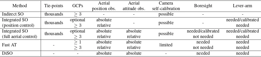
Method Tie-points GCPs Aerial
DiSO - - absolute absolute - needed needed
Table 1. Main sensor orientation approaches
1.2 MAV-specific challenges
The payload limitation of MAVs together with large and oscil-lating electromagnetic field caused by on-board equipment (e.g. motors, auxiliary electronics etc.) present the principal challenges in quality of position/attitude determination. Unlike a man pi-loted aircraft, MAVs cannot accommodate tactical or navigation grade IMU. Therefore, the MEMS based IMUs are the typical instruments employed on-board despite their lower quality. The lower temporal stability of biases in the inertial sensors together with the increased level of noise mean that static attitude initial-ization (alignment) cannot be performed, or in other words, the azimuth initialization is of very poor quality. As the observabil-ity of attitude errors is connected with time, short operations of MAVs are not in favour of such errors mitigation. Magnetometers may resolve this problem to a certain extend as long as operating within a constant and calibrated electromagnetic field, a condition that may be difficult to comply with.
Second possibility is to employ additional GNSS receiver(s) while maximizing the separation of antennas, (Eling et al., 2014). In most cases such separation is below 1 m level. Hence, the result-ing quality of azimuth initialization is likely comparable with that of a calibrated magnetometer. Another possibility is to reduce the noise level of an integrated system by employing several IMUs in parallel (Waegli et al., 2010). Apart noise mitigation, this allows determination of the actual noise level that may vary in time (due to vibrations) as well as the possibility of detecting faults (Guer-rier et al., 2012), which increases the redundancy of the system. Although an IMU of such type is employed in this study, the pre-sented content uses data separately from its sub-system, i.e. one IMU. Last but not least, low-noise of carrier-phase in the satellite signal is a prerequisite for cm-level differential positioning.
1.3 Paper structure
In the following part we present the aerial absolute and relative observations models together with their stochastic models. The third section concentrates on performance analysis in real map-ping scenarios. The MAV platform and its sensor payload are presented. The system calibration is then followed by the test data characterization. This section describes in detail the chal-lenges in processing due to the weak geometry and low texture quality of the testing site. The fourth part is devoted to the prac-tical evaluation during which we present the results of a variety of SO scenarios. Finally, the last part draws conclusions from the conducted research work.
2. AERIAL CONTROL MODELS
2.1 Absolute position and attitude control
The observation equation that models the relation between the imaging sensor and the IMU body frame, for which absolute
po-sition is derived, takes the form:
Xm=X0m+Rmc ·A
c
+Sm (1)
the superscriptmdenotes a Cartesian mapping frame and the sub-scriptcdescribes the camera sensor frame,Xm
is the GNSS/INS (Inertial Navigation System)-derived position for one epoch.Xm 0
is the camera projection centre,Rm
c is the nine-elements rotation
matrix fromctomframe,Ac
is the camera-GNSS antenna lever-arm andSm
is the possible positioning bias in GNSS-derived po-sitions. Note, that time is a parameter for all components in Eq. 1 with the exception ofAc
. The absolute attitude observations can be expressed by following equation:
Rmc =R
b is the GNSS/INS-derived attitude andR b
cis the IMU
- camera angular misalignment called boresight.
2.2 Relative position and attitude control
Relative observations relate the position and attitude parameters of two consecutive epochs (Li and Stueckmann-Petring, 1992, Blazquez and Colomina, 2012a). Differencing two sensor po-sitions results in an observation equation for coordinate differ-ences:
Wheretiand tjdistinguish the two epochs. In comparison to
Eq. 1, the term Sm
is canceled for certain (tj−ti) < ∆t.
The application of differencing makes use of the fact that certain effects of neighboring GNSS positions within strips or blocks are of a systematic nature. The attitude relative observations can be expressed as follows:
∆Rm
c (tij) =Rmb (tj)·Rbm(ti) (4)
Note, that the boresight parameter vanished in Eq. 4 compared to Eq. 2.
2.3 Stochastic models of relative aerial control
during a flight, depending on its duration. In Eq. 5, the param-eterσX(tij)represents the standard deviation of a relative posi-tion calculated according to Eq. 3 from two consecutive epochs
σX(ti)andσX(tj).
In the case of aerial attitude control, its stochastic models are somewhat more complicated. Given the quality and error char-acteristics of MEMS based IMUs, the on-line calibration process does not completely eliminate all systematic errors due to ob-servability issues. This may lead to unrealistic covariance matri-ces for the attitude estimates and incorrect stochastic modeling in BBA (Martinez et al., 2007). However, over a short time in-terval within a flight time (i.e. limited acceleration and orienta-tion changes), the accuracy of relative attitude aerial observaorienta-tions can be predicted by applying stochastic models for gyroscopes. In many cases this can be approximated as a superposition of a random walk (i.e. integrated white noise)ωRW and
uncali-brated gyro driftωb.
From our practical experience, the standard deviations of a rela-tive kappa angle shall differ from those of omega and phi. It is usually sufficient to multiplyωbby a constantk = 1.5. Again,
the approximation of Eq. 6 holds only within a short time∆t be-tween two consecutive images within the same flight line. In our evaluation, the maximal∆twas set to 10 seconds. This constraint eliminates the observations between the separate flight lines of the trajectory.
2.4 Implementation
The relative observation models were implemented into a custom BBA software. The latter was developed as the offer of com-mercially available software for BBA allowing relative position and attitude observations is very limited. In addition, custom im-plementation allows having full control of observation stochastic modeling that is particularly very important when using accurate aerial control. The nonlinear triangulation problem is reduced to an optimization problem which is solved using an iterative Gauss-Newton process. The solution of all observation equations for one set of values for unknown parameters is obtained by solving normal equations:
dx= (ATP A)−1ATP l (7)
Where,dxis a vector of corrections to unknowns parameters,A
is a model matrix containing partial derivatives of unknowns,P
is a weight matrix andlis a vector of observations, for further details see (Triggs et al., 2000).
3. PERFORMANCE ANALYSIS
In the following paragraphs, the properties and performance of the MAV sensor system are presented and evaluated. The pro-cessing chain is introduced with focus on testing different sensor orientation scenarios on two data sets. Particularly, we focus our effort on evaluating the contribution of relative aerial control and on finding the optimal setup and geometry configuration. The performance of the different sensor orientation approaches is an-alyzed through empirical accuracy of ground point determination. The mapping accuracy is measured at independent check points by Root-Mean-Square (RMS) indicator of the coordinate differ-ences.
3.1 MAV platform and sensors
The drone used for this study is a custom made airplane equipped with the open-source autopilot Pixhawk (Meier et al., 2012). The maximal payload capacity is around 800 g. The operational weight varies between 2200-2800 g and flying endurance is around 45 minutes. Thanks to its lightweight construction, the launching can be done from hand and it requires only a small place for land-ing. The payload comprises the 16 Mpx Sony NEX 5R camera, geodetic grade GNSS receiver and a redundant IMU (R-IMU) comprising four MEMS chips called Navchip (Intersense, 2015). The sampling frequencies are 10 Hz for the GNSS receiver and 500 Hz for the IMU, respectively. A second GNSS receiver and an antenna can be placed in the nose of the fuselage in the dis-tance of approximately 0.7 m from the first antenna. This allows the possibility of providing azimuth aiding, subject of which is, however, out of the scope of this contribution.
3.2 System calibration
System calibration is a process of determination of unknown sen-sor parameters and spatial relations between them. The sensen-sor calibration includes a camera calibration and IMU sensor error modeling. These procedures are well established and documented and will not be described here, for more details see for exam-ple (Fraser, 1997, Syed et al., 2007). In our case, the camera calibration was performed during a separate flight over a dedi-cated field. The camera interior parameters remained fixed in the BBA for certain SO scenarios, particularly for DiSO and Fast AT. In configurations with higher redundancy of observations, a self-calibration was performed. The IMU sensor error modeling com-prised a determination of random errors such as white noise, bias instability etc. and was performed using a method of Allan Vari-ance (Hou, 2004). The deterministic part was estimated by multi-position calibration.
Additionally, it is necessary to determine spatial offsets, so-called lever-arms, between the GNSS antenna and the IMU and between the IMU and the camera. This can be a very complicated task due to the usage of consumer grade cameras on unmanned aerial plat-forms. There, we followed the approach suggested by (Rehak and Skaloud, 2015) where camera EO are recovered in static condi-tions and differentiated with the posicondi-tions of the GNSS antenna surveyed by tachymetry.
When working with MEMS IMUs and imaging sensors not orig-inally foreseen for mapping, one has to very carefully select a proper calibration method. The boresight estimation can be done either within self-calibration adjustment (so-called one-step) or by comparing the GNSS/INS-derived attitude of images for which EO are estimated via (aerial position-aided) calibration block (so-called two-step procedure). In our case, the boresight misalign-ment was calibrated during a special calibration flight using self-calibration adjustment.
3.3 Test data
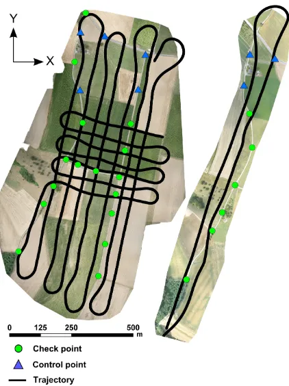
The flight for block scenario was performed during crop vege-tation stage and thus the surface suffers from strong homogene-ity. The image observations of tie-points were automatically mea-sured in the images using Pix4D mapper (Pix4D, 2015), the ob-servations of GCPs and ChP were obtained manually using its rayCloud engine. The quality of detected key-points and tie-points, respectively, is significantly degraded in certain areas. The Fig. 2 shows the distribution of tie-points and the gradient map represents a number of observations between these points and im-ages. The distribution of tie-points is rather regular with a very dense area in the central part. In the gradient map, shades of grey represent a number of observations. Darker the grey value, less image observations for a given area. It is clear that the border areas have less observations due to the missing overlaps. How-ever, the central part has also significantly less observations de-spite being flown from two directions at two different heights, as shown in Fig. 1. These weak areas make employment of indirect SO particularly very difficult as the tie-points cannot deliver suf-ficient precision due to the limited redundancy in observations. The aim of this study is to present the novel approaches of SO on the MAV on realistic data sets. Indeed, surface homogene-ity is very common in agricultural areas and given the expansion of precision farming, a number of applications need to deal with such surfaces on regular basis.
Regarding the accuracy assessment, 5 points were used as GCPs and 15 as independent ChPs. The placement of GCPs was such that it simulates mapping of badly accessible area with GCPs placed only in the vicinity of the launching area, Fig. 1. It is important to say that the very same points were used for all test-ing scenarios and in the case of DiSO, the GCPs were completely excluded. This procedure was identical for both tested data sets.
The corridor data set was collected over the same calibration field. The length and width of the latter were 1200 m and 180 m respectively. The differences in topology of this particular cor-ridor were around 30 m between the lowest and highest point. Out of 9 visible points in the corridor, the first three were used as GCPs and the rest as ChPs. Table 2 summarizes the most perti-nent facts of both data sets.
Data set characteristics Block 2015 Corridor 2014
Camera Sony NEX 5R Sony NEX 5R
Lens Sony 16 mm Sony 16 mm
IMU 4 x IMU 1 x IMU
GNSS 2 x Javad OEM 1 x Javad OEM
Flying height above gr. 120/150 m 130 m
Mean GSD 4.5 cm/pix 3.8 cm/pix
Overlap fwd./lat. 80/60 % 80/70 %
No. of photos 207 55
No. of GCPs 5 3
No. of GCPs obs. 94 32
No. of Check Points 15 6
No. of Check P. obs. 534 98
No. of Tie Points 4 926 1 595
No. of Tie Points obs. 105 552 17 040
Table 2. Summary of test data
3.4 Processing strategy
The data recorded during the flights were pre-processed in a way similar to mature mapping systems. The statistics on the number of tie points and corresponding observations is in Tab. 2. It is important to notice that the quality of tie points was somewhat lower than what can be expected from the state-of-the-art match-ing algorithms (e.g. 1-1.5 pix). This was particularly due to the
Figure 1. Flown missions; left: Block 2015, right: Corridor 2014
Figure 2. Distribution of tie-points and their observability
high homogeneity of the texture as discussed in Sec. 3.3. The GNSS data was processed in a professional software package. Thanks to the precise time synchronization between the camera and the GNSS receiver, the exact acquisition time of each image is directly known.
de-picts the residuals of attitude angles after BBA of the Block 2015 data. High residuals are obviously in omega and kappa angles. We can also observe repetitive patterns caused by correlation in attitude, e.g. due to initialization/alignment or by residual bore-sight. This somewhat less accurate attitude determination is of a less importance in the strong block configuration as its effect is mitigated by parallel strips, especially in the case of ISO with good distribution of tie-points. However, the influence on ground accuracy is more important further we go towards direct sensor orientation.
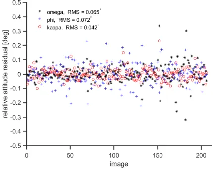
The solution for this problem offers relative orientation. By dif-ferentiating the attitude, we eliminate the effects of boresight as proved in Eq. 4 and mitigate the correlated part at the same time. To highlight this further, Fig. 4 shows the differences between initial relative attitude observations and relative attitude computed from adjusted attitude. It can be seen that the effects of residual boresight have vanished and the residuals have lower val-ues, random distribution and low RMS. The practical evaluation was done by calculating different SO methods. The particular combinations are listed in Tab. 3.
Figure 3. Absolute attitude residuals; influence of IMU residual boresight on attitude accuracy
Figure 4. Relative attitude residuals
Mode Pos. cont. Att. cont. Cam. cal. Boresight
Indirect SO - - Yes
-ISO Absolute Absolute Yes Known ISO Absolute Relative Yes -ISO Relative Relative Yes -Fast AT Absolute Absolute No Known Fast AT Absolute Relative No -Fast AT Relative Relative No
-DiSO Absolute Absolute No Known Table 3. Test configurations and their properties
4. PRACTICAL EVALUATION
In order to evaluate the accuracy of directly measured EO param-eters, a separate project with all GCPs was created for each data set. The residuals of EO parameters in BBA serve as indicators of accuracy of the directly measured positions and attitude in flight. The estimated accuracy of GNSS/INS-derived absolute positions was 3.5 cm horizontally and 3 cm in height. Regarding the atti-tude, the RMS of omega and phi angles was 0.045 deg and 0.125 deg for kappa.
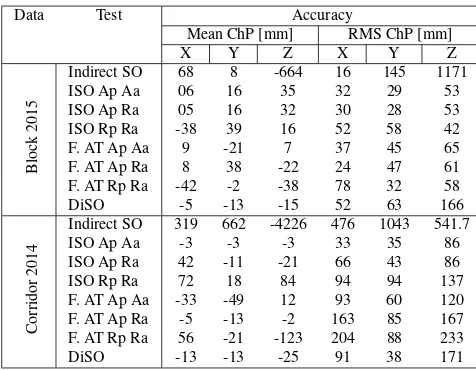
Looking at the results of the Block 2015 data set, Tab. 4, and given the average spatial resolution of 4.5 cm/pix, the achieved accuracy varies significantly between different SO approaches. As expected from the nature of the data, indirect SO fails com-pletely. The noisy image measurements together with weak ground control resulted in huge residuals at the check points. Next, three ISO projects were processed. Again, due to the lower quality of image measurements and poor distribution of GCPs, the accuracy is mainly driven by the aerial control. There, the relative attitude control slightly outperforms the absolute by eliminating the rela-tively high attitude residuals as seen in Fig. 3. When removing image observations of tie-points from the adjustment and using Fast AT method, we can obtain similar results to that of ISO. There, the usage of absolute and relative aerial control together with a few GCPs and a very limited number of image measure-ments is sufficient to provide an accuracy of 1.5 pixel both in position and height while being significantly faster in processing. The inclusion of relative attitude control improved the accuracy more than the absolute control. On the other hand, relative po-sition control weakens the geometry in Fast AT as a significant shift is present in the X axis. The accuracy of DiSO corresponds to less than 2 pixels in position and around 3.5 pix in height.
Data Test Accuracy
Mean ChP [mm] RMS ChP [mm]
X Y Z X Y Z
Block
2015
Indirect SO 68 8 -664 16 145 1171
ISO Ap Aa 06 16 35 32 29 53
Indirect SO 319 662 -4226 476 1043 541.7
ISO Ap Aa -3 -3 -3 33 35 86
Table 4. Accuracy assessment at independent check points; Block 2015 represents the block with 5 GCPs and 15 ChPs, the Corridor 2014 has 3 GCPs and 6 ChPs; the Test acronyms correspond to those in Tab. 3
5. CONCLUSION AND PERSPECTIVES
This paper aimed at testing novel observation models in the con-text of MAVs. The initial part discussed the general problematic of sensor orientation with a specific focus on accurate mapping of difficult areas. The following part focused on theoretical de-scription of mathematical models of absolute and relative aerial control and their implementation into a custom bundle adjust-ment software. An in-house developed MAV platform was used as a carrier of imaging and navigation sensors. Two data sets were acquired and served for quality evaluation. The flights were executed over a dedicated calibration field and the accuracy was evaluated at independent check points. Several mapping projects were presented with focus on scenarios with accurate aerial con-trol.
It was shown that thanks to the aerial control, accurate mapping is possible even with areas with badly distributed GCPs. The main contribution of attitude absolute and relative control is the elim-ination of AT block structure and reduction of ground control in mapping configurations with weak geometry. Contrary, the con-tribution of attitude observation in strong AT blocks with well distributed tie points is rather limited. With relation to UAVs and MAVs in particular, the relative observations have great potential since the need of boresight calibration is omitted and therefore the process of sensor integration facilitated. The best achieved accuracy lies in the level of approx. 1 pixel, both in position and height. This accuracy is usually hardly achievable with conven-tional methods of sensor orientation i.e. indirect SO or ISO with absolute aerial control.
For certain projects with lower demands on accuracy, DiSO rep-resents a very convenient and rapid way of mapping. Finally, Fast AT proved to be an excellent compromise between ISO and DiSO particularly in the context of relative attitude control. This method provides accuracy close to ISO while by speed and de-mands on configuration, e.g. image overlaps, is close to DiSO. Fast AT also offers considerable higher degree of robustness than DiSO.
REFERENCES
Blazquez, M. and Colomina, I., 2012a. Fast AT: a simple proce-dure for quasi direct orientation. ISPRS Journal of Photogram-metry and Remote Sensing71, pp. 1–11.
Blazquez, M. and Colomina, I., 2012b. Relative INS/GNSS aerial control in integrated sensor orientation: models and perfor-mance. ISPRS Journal of Photogrammetry and Remote Sensing 67, pp. 120–133.
Colomina, I., 1999. GPS, INS and aerial triangulation: What is the best way for the operational determination of photogrammet-ric image orientation.International Archives of Photogrammetry, Remote Sensing and Spatial Information Sciences32, pp. 121– 130.
Colomina, I., 2007. From off-line to on-line geocoding: the evo-lution of sensor orientation. In: D. Fritsch (ed.), Photogrammet-ric Week, Wichmann Verlag, Stuttgart, pp. 173–183.
Colomina, I. and Molina, P., 2014. Unmanned aerial systems for photogrammetry and remote sensing: a review. International Archives of Photogrammetry, Remote Sensing and Spatial Infor-mation Sciences92(6), pp. 79–97.
Eling, C., Klingbeil, L., Wieland, M. and Kuhlmann, H., 2014. Direct georeferencing of micro-aerial vehicles - system design, system calibration and first evaluation tests. Journal of pho-togrammetry, remote sensing and geoinformation processing (PFG)4, pp. 227–237.
Fraser, C., 1997. Digital camera self-calibration.ISPRS Journal of Photogrammetry and Remote Sensing52(4), pp. 149–159.
Guerrier, S., Waegli, A., Skaloud, J. and Victoria-Feser, M.-P., 2012. Fault detection and isolation in multiple MEMS-IMUs configurations. IEEE Transactions on Aerospace and Electronic Systems48, pp. 2015–2031.
Hou, H., 2004. Modeling inertial sensors errors using Allan vari-ance. Master Thesis, University of Calgary, Department of Geo-matics Engineering, Calgary, Canada.
Intersense, 2015. Navchip. http://www.intersense.com/ pages/16/246/. [Online; accessed 12-December-2015].
Legat, K., Skaloud, J. and Schmidt, R., 2006. Reliability of di-rect georeferencing phase 2: A case study on practical problems and solutions. In: Checking and Improving of Digital Terrain Models / Reliability of Direct Georeferencing., EuroSDR Official Publication 51.
Li, K. and Stueckmann-Petring, J., 1992. Methods and re-sults of combined adjustment utilizing kinematic GPS position-ing and photogrammetric data. International Archives of Pho-togrammetry, Remote Sensing and Spatial Information Sciences 29, pp. 213–213.
Martinez, M., Blazquez, M., Gomez, A. and Colomina, I., 2007. A new approach to the use of position and attitude control in cam-era orientation. In:7th International Geomatic Week, Barcelona, Spain.
Mavinci, 2015. Sirius Pro. http://www.mavinci.com. [On-line; accessed 15-November-2015].
Mian, O., Lutes, J., Lipa, G., Hutton, J., Gevalle, E. and Borgh-ini, S., 2015. Direct georeferencing on small unmanned aerial platforms for improved realibility and accuracy of mapping with-out the need of ground control points.The International Archives of the Photogrammetry, Remote Sensing and Spatial Information SciencesXL-1/W4, pp. 397–402.
Pix4D, 2015. Pix4D Mapper. http://pix4d.com/. [Online; accessed 15-November-2015].
Rehak, M. and Skaloud, J., 2015. Fixed-wing micro aerial ve-hicle for accurate corridor mapping. ISPRS Annals of the Pho-togrammetry, Remote Sensing and Spatial Information Sciences II-1/W4, pp. 23–31.
Rehak, M., Mabillard, R. and Skaloud, J., 2014. A micro aerial vehicle with precise position and attitude sensors. Journal of photogrammetry, remote sensing and geoinformation processing (PFG)4, pp. 239–251.
Schwarz, K. P., Chapman, M., Cannon, M. and Gong, P., 1993. An integrated INS/GPS approach to the georeferencing of re-motely sensed data. Photogrammetric Engineering and Remote Sensing59(11), pp. 1167–1674.
senseFly, 2015. eBee RTK.http://www.sensefly.com. [On-line; accessed 15-November-2015].
Skaloud, J., 2006. Reliability of direct georeferencing phase 1: An overview of the current approaches and possibilities. In: Checking and Improving of Digital Terrain Models / Reliability of Direct Georeferencing, EuroSDR Official Publication 51.
Skaloud, J., Cramer, M. and Schwarz, K. P., 1996. Exterior ori-entation by direct measurements of camera position and attitude. International Archives of Photogrammetry, Remote Sensing and Spatial Information Sciences31(B3), pp. 125–130.
Skaloud, J. Rehak, M. and Lichti, D., 2014. Mapping with MAV: Experimental study on the contribution of absolute and relative position control.The International Archives of the Photogramme-try, Remote Sensing and Spatial Information Sciences40-3/W1, pp. 123–129.
Syed, Z. F., Aggarwal, P., Goodall, C., Niu, X. and El-Sheimy, N., 2007. A new multi-position calibration method for MEMS inertial navigation systems. Measurement Science and Technol-ogy18(7), pp. 1897–1907.
Triggs, B., McLauchlan, P. F., Hartley, R. I. and Fitzgibbon, A. W., 2000. Bundle adjustment - a modern synthesis. In: Vi-sion algorithms: theory and practice, Springer, pp. 298–372.