Technische Universit¨at Dresden, DE-01062 Dresden, Germany Institute of Photogrammetry and Remote Sensing
(david.mader, robert.blaskow, patrick.westfeld, hans-gerd.maas)@tu-dresden.de http://www.tu-dresden.de/ipf/photo
KEY WORDS:Unmanned aerial vehicle, 3D point cloud, LIDAR, structure from motion, laser scanning range finder, RGB camera
ABSTRACT:
The Project ADFEX (Adaptive Federative 3D Exploration of Multi Robot System) pursues the goal to develop a time- and cost-efficient system for exploration and monitoring task of unknown areas or buildings. A fleet of unmanned aerial vehicles equipped with appropri-ate sensors (laser scanner, RGB camera, near infrared camera, thermal camera) were designed and built. A typical operational scenario may include the exploration of the object or area of investigation by an UAV equipped with a laser scanning range finder to generate a rough point cloud in real time to provide an overview of the object on a ground station as well as an obstacle map. The data about the object enables the path planning for the robot fleet. Subsequently, the object will be captured by a RGB camera mounted on the second flying robot for the generation of a dense and accurate 3D point cloud by using of structure from motion techniques. In addition, the detailed image data serves as basis for a visual damage detection on the investigated building.
This paper focuses on our experience with use of a low-cost light-weight Hokuyo laser scanner onboard an UAV. The hardware com-ponents for laser scanner based 3D point cloud acquisition are discussed, problems are demonstrated and analyzed, and a quantitative analysis of the accuracy potential is shown as well as in comparison with structure from motion-tools presented.
1. INTRODUCTION
Unmanned Aerial Vehicles (UAVs) are small and versatile air-crafts at a reasonable price. Their modular structure allows ple and time-saving adjustments for certain requirements and sim-plifies the maintenance. Due to these characteristics, UAVs find large interest as a tool for a wide spectrum of civil applications such as exploration, monitoring, inspection or rescue tasks as well as large-scale aerial photogrammetry. The interdisciplinary Project ADFEX (Adaptive Federative 3D Exploration of Multi Robot Systems) shall carry out the ambitious goal of data acqui-sition for exploration and monitoring tasks by an autonomous op-erating group of flying robots. Three robots have been developed and constructed using standard sensors for navigation and for ob-stacle detection (GPS, IMU, ultrasonic sensors). In addition, the UAVs are equipped with special sensors for acquisition of differ-ent tasks, which can be adapted to differdiffer-ent applications. A laser scanning range finder (LSRF) enables a real-time generation of 3D point clouds with reduced accuracy to provide an overview of the object and to facilitate obstacle mapping and path planning. Images captured with RGB-, near-infrared and thermal-infrared cameras form a basis for the reconstruction of more accurate 3D point clouds by using structure from motion (SfM) processing methods. A cost and time efficient exploration and monitoring should be achieved by a simultaneous task-sharing flight of the three robots with a continuous two-way data stream between the robots and the ground station. More information can be found on the websitehttp://www.adfex.eu/. Other studies also at-tend on UAVs equipped with light-weight imaging sensors. In (Ahmed et al., 2008) UAVs were utilized as aircrafts, which were flying at a very low altitude to get high resolution images of the ground. Based on these images, victims in disaster areas can be detected and rescued. Israel (2011) described a thermal detec-tion system for saving lives of fawns in meadows on basis of images captured by a thermal camera mounted on an UAV. An
∗Corresponding author
efficient usage for monitoring of soil erosion is shown in (Eltner et al., 2013), where an UAV equipped with a camera was used for data acquisition. The authors in (Roca et al., 2014) produced 3D point clouds for building assessment with a combination of light-weight laser scanning range finder and an unmanned air-craft. A processing chain for operator guidance through an UAV based building reconstruction by the help of SfM techniques is described in (Daftry et al., 2015).
This paper will focus on our experience in generating 3D point clouds from low-cost laser scanner data in comparison to SfM techniques on basis of RGB images, both mounted on UAVs. The first part presents a brief overview about the specification of the sensors mounted on the UAV and the flying platform itself. The second part deals with the acquisition and processing of 3D point clouds as well as an analysis of the results. Finally, this constri-bution will finish with a conclusion, an outlook and future work.
2. HARDWARE
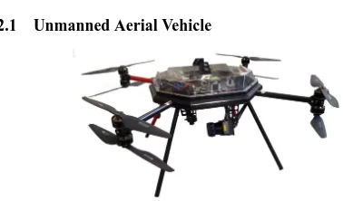
2.1 Unmanned Aerial Vehicle
Figure 1: UAV Cadmic Goliath Coax 8 frame.
(a)
(b)
Figure 2: (a) Image of the investigated bridge. (b) Overview of the entire 3D point cloud based on data from LSRF.
eight coaxial mounted rotors (Figure 1). For the determination of the robots position and orientation, the raw data of a single-frequency GPS-receiver u-blox LEA-6T and an IMU-module 10-DOF-IMU ADIS16407 are processed. The advantage of the mod-ular structure of the robots in comparison to black box systems is the easy access to every component in case of maintenance or emergency. The payload is about 1 kg, which is sufficient in order to carry passive or active 2D/3D sensor systems at a reasonable flight time of about 10 min to 15 min per battery charge.
2.2 Hokuyo UTM-30LX-EW
One of the platforms is equipped with a laser scanner UTM-30LX-EW from Hokuyo (Figure 3a). It is a 2D laser scanning range finder (LSRF), capturing distances in a plane. The dis-tance measurement unit operates according to the time-of-flight principle. Due to the low weight of only 210 g and the com-pact size (62 mm×62 mm×87.5 mm), the LSRF is predestinated to be used on UAVs. The field of view is 270◦ with a resolu-tion of 0.25◦, which results in 1080 distance measurement per line during a 1/40 seconds. The LSRF works in a range of 0.1 m up to 30 m with an accuracy of 30 mm to 50 mm (specified by manufacturer). An important fact for subsequent error analysis is the elliptical laser footprint with a beam divergence of about 1.0◦
×0.1◦, which is rotating during a scan (Figure 3b).
(a)
Perfect scanning plane (without width)
(b)
Figure 3: (a) Laser scanning range finder Hokuyo UTM-30LX-EW (Hokuyo, 2014a). (b) Schematic representation of the laser beam footprint (specified by manufacturer); the figure shows the effect of a rotating elliptical laser beam profile (Hokuyo, 2014b).
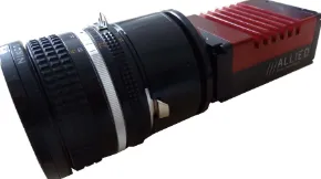
2.3 AVT Prosilica GT3300C
For high quality image acquisition, a CCD camera 3296×2472 px Prosilica GT3300C (Figure 4) from Allied Vision Technologies is used. The pixel size is 5.5 µm, and the maximum frame rate is 14.7 images per second. With a weight of 314 g for the camera
body and dimensions of 121 mm×59.7 mm×59.7 mm, it is still suitable for use on UAVs with a sufficient payload. For the cap-ture in this contribution, a lens with a fixed focal length of 20 mm was used. This sensor-lens combination (crop factor = 1.91) is equivalent to a full format sensor and a focal length of 38.19 mm.
Figure 4: Prosilica GT3300C RGB camera.
3. CALIBRATION
To receive high-quality results, a calibration of the entire system and the sensors is indispensable. An entire system calibration comprises the lever arm as well as the boresight angles between the coordinate systems of the LSRF, the camera and the UAV’s navigation sensors. The sensor calibration also includes the in-terior parameters such as camera lens distortions or distance cor-rections for the LSRF. Both were carried out simultaneously in an integrated self-calibration strategy to guarantee a correct calcula-tion with different observacalcula-tion types. An adaptive fully integrated and modularly structured bundle adjustment is shown in (Mader et al., 2014), which was extended with geometric and stochastic models for the determination of lever arm and boresight angles for the particular sensor-UAV combination.
4. 3D POINT CLOUDS BASED ON LSRF DATA
4.1 Acquisition and data processing
As research object a bridge (Figure 2a) with dimensions of 12 m in width, 135 m in length and 8 m in height, was selected. Scans alongside the bridge with low speed of the UAV guaranteed a sufficient number of scan lines for a good representation of the bridge in LSRF data. In total 20,000 scan lines were recorded in a flight-time of approximately 10 min with an average altitude of 5 m and an average UAV-object distance of 12 m. Additional flights underneath the bridge were also flown for test purposes,
(a)
(b)
Figure 5: Horizontal profile of pillars from TLS (gray)- and LSRF (blue, red) point cloud with: (a) incorrect yaw angle measurements. (b) corrected yaw angles by approximate correction terms. The pillars are 14.1 m in length and 1.4 m in width.
but as expected the LSRF measurement could not be used due to GPS signal loss. As stated above, the LSRF provides 40 scan lines per second, each with 1080 distance and intensity measure-ments. Each scan line of the LSRF and the UAV pose informa-tion gets a timestamp for synchronizing the acquired data. Due to the fact that the LSRF and navigation sensors are not hardware-triggered and thus not congruent, the pose of every scan line had to be linear interpolated depending on the timestamps. For 3D point cloud generation, the first step is the conversion from mea-sured spherical coordinates (distanceD, horizontal angleα, ver-tical angleβ) into the local laser scanner coordinate system re-spectively the sensor coordinate system (scs). In this particular case (the used LSRF performs 2D scans) the vertical angle com-ponentβand thus the resulting Z-component are zero in the scs system.
D : measured distance from LSRF
α : horizontal deflection angle
β : vertical deflection angle (:= 0)
Subsequently, the point coordinates are transformed into the UAV coordinate system (rcs - robot coordinate system) by using the calibrated lever arm and boresight angles.
Xrcs=Xla+Rrcs
scs·X scs
(2)
where
Xla : lever arm in roboter coordinate system (rcs)
Rrcs
scs : rotation matrix of boresight angles
Xrcs : object point in roboter coordinate system (rcs)
Finally, on basis of the navigation data the measured points are mapped into the WGS84 reference frame. For that the point co-ordinates are transformed into the navigation system
(north-east-down coordinate system - ned), with
Xned=Rz(ψ)·Ry(θ)·Rx(φ)·Xrcs (3)
where
φ, θ, ψ : orientation angles based on IMU measurements
Xned : object point in navigation coordinate system (ned)
and from north-east-down in the WGS84 (wcs - world coordinate system) with:
Xwcs : object point in WGS84 coordinate system (wcs)
Xwcs
ned : UAV-position in WGS84 coordinate system (wcs)
The final coordinates results from an addition with the corre-sponding UAV-position. A detailed description of the transfor-mation between the robot coordinate system and the WGS84 can be found in (B¨aumker and Heimes, 2001).
4.2 Result
2.750 m 2.406 m
2.063 m
1.719 m
1.375 m
1.031 m
0.688 m
0.344 m
0.000 m 35 m
(a)
0 500 1000 1500 2000
0 2 4 6 8 10
12x 10
4
66.6 % of deviation < 294.2 mm
absolute deviations [mm]
frequency
(b) (c) (d)
Figure 6: (a) Color-coded absolute distances between LSRF and TLS point clouds obtained by CloudCompare. (b) Histogram of absolute distances. (c) Good represented part of the bridge by LSRF points. (d) Bad represented part of the bridge by LSRF points caused by inaccurate IMU angles in lateral direction. Red points are the flight path of the UAV.
distances (˜ 30 mm to 50 mm) is negligible. The lever arm and boresight angles, which were determined by an appropriate cali-bration strategy, have also a low influence. The weakness is ob-viously the accuracy of measured GPS-heights (Figure 7a), how-ever it can be improved by an additional barometric altitude mea-surement, as one can see in Figure 7b. In Figure 5a, a horizontal section through the bridge pillars is shown to illustrate the im-pact of inaccurate yaw angles. This effect was probably caused by the influence of electromagnetic fields from the UAV’s elec-tronic components to the magnetometer. The torsion is clearly evident in comparison to a terrestrial laser scanner (TLS) point cloud, which was captured with a high-precision Z&F Imager 5006 laser scanner and used as reference. A rough correction term for the yaw angles was determined by an alignment of the pillars horizontal profile from LSRF point cloud to the TLS point cloud and considered in the processing chain of UAV point cloud generation (Figure 5b). The corrected point cloud still contains lateral GPS-inaccuracies. For quantifying this fact, a compari-son between the LSRF and TLS point clouds was done. There-for, the LSRF point cloud was transformed in two steps onto the TLS point cloud. First step is a coarse alignment with three bet-ter more homologous points and second step is the fine regis-tration by an iterative closest point (ICP) algorithm. Afterwards the cloud to cloud distances were calculated. The result shows a sufficient inner geometrical accuracy for a rough point cloud (Figure 6a). The LSRF point cloud shows a deviations root mean square value (RMS) of about 31.7 cm, with2/3of all points hav-ing deviations less than 29.4 cm. Figure 6b show the distribution of the deviation compared to the TLS point cloud. These lateral effects might be reduced by a stronger weighting of the IMU ac-celeration measurements in the GPS/IMU data processing. Other GPS based approaches such as real time kinematic (RTK) or dif-ferential GPS (DGPS) are also possible shown in (Stempfhuber and Buchholz, 2011) and (Heredia et al., 2009). The expected 3D platform position accuracy is about few centimeter for both. However, RTK and DGPS navigation are not robust for signal loss caused by shadowing effects. Due to this fact, an addi-tional improvement of the used navigation solution may be ob-tained from sensors like a navigation camera in a visual SLAM approach similar to (Georgiev and Allen, 2004). A further
as-pect for enhancement would be an appropriate magnetometer cal-ibration as described in (Gebre-Egziabher, 2007, Dorveaux et al., 2009, Metni et al., 2006) or improved protection against signal interfering radiation through EMI shields. Figure 6d discloses a major problem caused by direct dependencies of navigation solu-tion, in this case the IMU angles. Nevertheless, Figure 6c shows a well captured bridge part and confirms the potential of this cap-turing system benefiting from smaller direction changes of the UAV. Despite the above mentioned problems, the generated 3D point cloud is suitable for a good overview of the object or for obstacle avoidance.
(a)
(b)
Figure 7: Effects of inaccurate GPS-height measurements: (a) LSRF point cloud with GPS-heights. (b) LSRF point cloud with barometric heights.
Figure 8: RGB-colored 3D point cloud from SfM.
5. 3D POINT CLOUDS BASED ON IMAGE DATA
5.1 Acquisition and data processing
In a second flight campaign, the bridge mentioned above was im-aged by a RGB camera rigidly mounted on the UAV. The entire flight-time for two flights alongside the bridge plus flights around all four bridge pillars was 80 min. About 500 images were cap-tured with an overlap of at least 80 % in flight direction. To ensure an optimal image quality including sharpness and homogenous brightness during the complete flight, the balance between aper-ture, exposure time and gain is important. A too long exposure time leads to blur effects caused by the motion and vibration of the flying platform. To receive optimal pictures for further pro-cessing with SfM methods, aperture and gain was coordinated. During this procedure, too small aperture values as well as too high gain values were avoided. The bridge was reconstructed on basis of images only by SfM-tools, in this case with the commer-cial software package Agisoft Photoscan. The general principle of SfM has often been presented in literature like (Koenderink and Van Doorn, 1991), (Beardsley et al., 1997) and (Pollefeys et al., 2000). For the presented reconstruction no additional prior in-formations such as GPS positions or image sequence details are used during the matching process. SfM techniques provide 3D object informations from overlapping image sequences. Knowl-egde about inertial information from the captured object or cam-era poses are not necessary but can reduce processing time and wrong camera pose estimation. Initially, a feature point measure-ment in every image was carried out by a feature detection opera-tor such as SIFT (Lowe, 1999) or SURF (Bay et al., 2008). After pairwise matching based on detected features, the exterior orien-tations of the images and a sparse point cloud were reconstructed. The final results of the procedure were a dense point cloud and refined exterior orientations.
5.2 Result
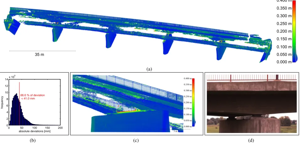
The resulting RGB-colored 3D point cloud shown in Figure 8 consists of 13 million points (bridge only) and represents the bridge in a high degree of detail. To analyze the geometrical ac-curacy, a comparison with the TLS reference point cloud was per-formed. Therefore the same procedure as in section 4.2 was car-ried out. The color-coded deviations between both point clouds are shown in Figure 9a. The deviations RMS value is 4.9 cm, with 2/3of the SfM point cloud having deviations less than 4.1 cm (Figure 9b). These deviations can be explained on the one hand
by a suboptimal capture setup (only one row of images), which has a bad effect to the SfM error propagation. And on the other hand the largest deviations can be found at points near discontin-ues underneath the bridge (Figure 9c) caused by a lack of texture and brightness in the images. The shown result is a good data basis for any further processing to a meshed 3D visualization for use within 3D city model. The quality of the point cloud is also sufficient for measurements in the object and for building recon-struction. The processing and evaluation was performed with the open source project CloudCompare. Beyond measuring in the point cloud, there is the possibility to use the images (including their improved georeferencing information) for visual inspection such as damage detection/localization on buildings (Figure 9d).
6. CONCLUSION
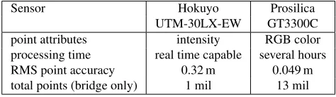
The paper presents and compare the generation of 3D point clouds on the basis of data from a low-cost LSRF and a RGB camera mounted on a UAV. Properties of the resulting point clouds are presented in Table 1. A processing chain from raw data to 3D object points was shown in an overview as well as remarks for improvements was shown. A comparison of the LSRF with a TLS reference point cloud provides a good estimate of the ac-curacy potential. A real-time generation of a coarse point cloud based on measurement data of the presented LSRF system is pos-sible. The resulting point cloud with RMS deviations of about 32 cm is sufficiently to give an overview of the measured object and may also be used for path planning and obstacle avoidance. However, the quality of the LSRF point cloud depends directly on the quality of the UAV’s positioning devices, so that the navi-gation solution should be improved for better results. In a second campaign, the bridge was captured by a RGB camera mounted on a UAV. On basis of the overlapping images, a RGB-colored 3D point cloud was generated. A comparison with the TLS refer-ence point cloud showed a high geometrical quality in the order of 5 cm.
Sensor Hokuyo Prosilica
UTM-30LX-EW GT3300C
point attributes intensity RGB color
processing time real time capable several hours
RMS point accuracy 0.32 m 0.049 m
total points (bridge only) 1 mil 13 mil
0.400 m
Figure 9: (a) Color-coded absolute distances between SfM and TLS point clouds obtained by CloudCompare. (b) Histogram of absolute distances. (c) Section of the SfM point cloud showing good points (blue), inaccurate points (red) and holes in the point cloud. (d) Images of the SfM network can be used for visual inspection for instance to detect and localize damage on buildings.
7. OUTLOOK AND FUTURE WORK
Further work will be focus on the enhancement of both point clouds. In case of the SfM point cloud, the acquisition of the poorly illuminated bridge areas will be improved to close the gaps in the resulting point cloud. Further step will be coarse georefer-encing by using UAV-positioning data. For the LSRF point cloud, improvements in the navigation solution might be achieved by us-ing a navigation camera and a visual SLAM algorithm. Thus the resulting point cloud will be more accurate, and scanning under-neath the bridge will be possible due to the reduced vulnerability to GPS signal loss. In addition to that, a reasonable calibration strategy for the IMU will be worked out. An other aspect of fu-ture work will be a LSRF strip adjustment for optimization of the point cloud geometry. Furthermore, an integrated point cloud generated by a quality parameter ruled merging process of the SfM and LSRF point clouds will improve the completeness and consistency of the results.
ACKNOWLEDGEMENTS
The research work presented in this paper has been funded by the European Social Fund (ESF) via S¨achsische Aufbaubank (SAB). We would also like to thank our partners in the ADFEX project for their support and the great collaboration.
REFERENCES
Ahmed, A., Nagai, M., Tianen, C. and Shibasaki, R., 2008. UAV based monitoring system and object detection technique development for a disaster area. International Archives of Pho-togrammetry, Remote Sensing and Spatial information Sciences 37, pp. 373–377.
B¨aumker, M. and Heimes, F., 2001. New calibration and comput-ing method for direct georeferenccomput-ing of image and scanner data using the position and angular data of an hybrid inertial naviga-tion system. In: OEEPE Workshop, Integrated Sensor Orienta-tion.
Bay, H., Ess, A., Tuytelaars, T. and Van Gool, L., 2008. Speeded-up robust features (SURF). Computer vision and image under-standing 110(3), pp. 346–359.
Beardsley, P. A., Zisserman, A. and Murray, D. W., 1997. Se-quential updating of projective and affine structure from motion. International journal of computer vision 23(3), pp. 235–259.
Daftry, S., Hoppe, C. and Bischof, H., 2015. Building with drones: Accurate 3D facade reconstruction using MAVS. arXiv preprint arXiv:1502.07019.
Dorveaux, E., Vissiere, D., Martin, A.-P. and Petit, N., 2009. It-erative calibration method for inertial and magnetic sensors. In: Decision and Control, 2009 held jointly with the 2009 28th Chi-nese Control Conference. CDC/CCC 2009. Proceedings of the 48th IEEE Conference on, IEEE, pp. 8296–8303.
Eltner, A., Mulsow, C. and Maas, H.-G., 2013. Quantitative measurement of soil erosion from TLS and UAV data. ISPRS-International Archives of the Photogrammetry, Remote Sensing and Spatial Information Sciences 1(2), pp. 119–124.
Gebre-Egziabher, D., 2007. Magnetometer autocalibration lever-aging measurement locus constraints. Journal of aircraft 44(4), pp. 1361–1368.
Georgiev, A. and Allen, P. K., 2004. Localization methods for a mobile robot in urban environments. Robotics, IEEE Transac-tions on 20(5), pp. 851–864.
Heredia, G., Caballero, F., Maza, I., Merino, L., Viguria, A. and Ollero, A., 2009. Multi-unmanned aerial vehicle (UAV) coop-erative fault detection employing differential global positioning (DGPS), inertial and vision sensors. Sensors 9(9), pp. 7566– 7579.
Hokuyo, 2014a. Product Information UTM-30LX-EW. Hokuyo Autmatic Co., Ltd., Japan.
Hokuyo, 2014b. UTM LaserSpot Information. Hokuyo Autmatic Co., Ltd., Japan.
Lowe, D. G., 1999. Object recognition from local scale-invariant features. In: Computer vision, 1999. The proceedings of the sev-enth IEEE international conference on, Vol. 2, Ieee, pp. 1150– 1157.
Mader, D., Westfeld, P. and Maas, H.-G., 2014. An inte-grated flexible self-calibration approach for 2D laser scanning range finders applied to the Hokuyo UTM-30LX-EW. ISPRS-International Archives of the Photogrammetry, Remote Sensing and Spatial Information Sciences 1, pp. 385–393.
Metni, N., Pflimlin, J.-M., Hamel, T. and Sou`eres, P., 2006. At-titude and gyro bias estimation for a VTOL UAV. Control Engi-neering Practice 14(12), pp. 1511–1520.
Pollefeys, M., Koch, R., Vergauwen, M., Deknuydt, A. A. and Van Gool, L. J., 2000. Three-dimensional scene reconstruction from images. In: Electronic Imaging, International Society for Optics and Photonics, pp. 215–226.
Roca, D., Armesto, J., Lag¨uela, S. and D´ıaz-Vilari˜no, L., 2014. Lidar-equipped UAV for building information modelling. ISPRS-International Archives of the Photogrammetry, Remote Sensing and Spatial Information Sciences 1, pp. 523–527.