3D RECONSTRUCTION OF AN UNDERWATER ARCHAELOGICAL SITE:
COMPARISON BETWEEN LOW COST CAMERAS
A. Capra a *, M. Dubbini b , E. Bertacchini a , C. Castagnetti a , F. Mancini a
a DIEF, Dept. Engineering “Enzo Ferrari”, University of Modena e Reggio Emilia, via Pietro Vivarelli 10/1, 41125 Modena, Italy – (alessandro.capra, eleonora.bertacchini, cristina.castagnetti, francesco.mancini)@unimore.it
b DiSCi, Dept. History Culture Civilization- Headquarters of Geography, University of Bologna, via Guerrazzi 20, 40125 Bologna, - ([email protected])
Commission V
KEY WORDS: Photogrammetry, Underwater, 3D reconstruction, Archaeological, Calibration and Orientation, Cultural Heritage
ABSTRACT:
The 3D reconstruction with a metric content of a submerged area, where objects and structures of archaeological interest are found, could play an important role in the research and study activities and even in the digitization of the cultural heritage. The reconstruction of 3D object, of interest for archaeologists, constitutes a starting point in the classification and description of object in digital format and for successive fruition by user after delivering through several media. The starting point is a metric evaluation of the site obtained with photogrammetric surveying and appropriate 3D restitution. The authors have been applying the underwater photogrammetric technique since several years using underwater digital cameras and, in this paper, digital low cost cameras (off-the-shelf). Results of tests made on submerged objects with three cameras are presented: © Canon Power Shot G12, © Intova Sport HD e © GoPro HERO 2. The experimentation had the goal to evaluate the precision in self-calibration procedures, essential for multimedia underwater photogrammetry, and to analyze the quality of 3D restitution. Precisions obtained in the calibration and orientation procedures was assessed by using three cameras, and an homogeneous set control points. Data were processed with © Agisoft Photoscan. Successively, 3D models were created and the comparison of the models derived from the use of different cameras was performed. Different potentialities of the used cameras are reported in the discussion section. The 3D restitution of objects and structures was integrated with sea bottom floor morphology in order to achieve a comprehensive description of the site. A possible methodology of survey and representation of submerged objects is therefore illustrated, considering an automatic and a semi-automatic approach.
* Corresponding author
1. INTRODUCTION
The seabed is often defined as "the greatest museum in the world." The underwater cultural heritage includes all traces of human existence that lie beneath the water and have a cultural or historical character. Entire cities have been swallowed up by the waves, and thousands of ships have been lost at sea. While these ships, buildings and historical objects are not visible on the surface, their remains have survived to the bottom of lakes, seas and oceans stored safely in the aquatic environment. This heritage includes three million ancient shipwrecks, their content, submerged ruins, cities and thousands of prehistoric sites. In 2001, UNESCO, given the urgent need to preserve and protect this heritage submerged, drafted the "Convention on the Protection of Underwater Cultural Heritage". So that everyone can benefit from this immense underwater cultural heritage (both the visitor that the technician), in recent years the reproduction of digital three-dimensional models with high resolution and high geometric accuracy, is the methodology that is being adopted. The underwater photogrammetric technique appears to be the most appropriate methodology for this
the description of the object color (texture), which appears to be essential for many types of studies.
The underwater photogrammetry is a technique that since the year 80 is effective for the geometric description of submerged objects (Capra, 1992; Troisi et al., 2013). The main goal is the determination of the interior orientation parameters of the camera because of multimedia resources (water, glass, air, lenses, air).
This article focuses on the definition of the parameters of interior orientation of three types of cheap camera (© Canon Power Shot G12, © Intova Sport HD e © GoPro HERO 2), comparing them after their determination using photogrammetric algorithms, very often implemented by the computer vision sciences (for instance the Structure from Motion with bundle adjustment), and a commercial software (PhotoScan, ©Agisoft) Figure 1 as location map. Figure 2 represents the Dressel Table, reporting a classification of amphoras based on shapes. Figure 3 depicts the amphora Dressel B1 as visible on the seabed. The International Archives of the Photogrammetry, Remote Sensing and Spatial Information Sciences, Volume XL-5/W5, 2015
Figure 1. Site of Operation
Figure 2. Dressel Table
Figure 3. Amphora Dressel B1 on the seabed
3. USED CAMERAS
As said, 3 different low cost cameras were used for this test in order to assess their reliability under the operational conditions. In Table 1, Table 2 and Table 3 the main characteristics of the used cameras.
© Canon Power Shot G12:
Image Sensor CCD 1 / 1.7''
Resolution 10M 3648 x 2736 pixel
12211.538 dpi
Focal Length from 6,1 to 30,5 mm (equivalent a 35
mm: 28 - 140 mm)
Zoom 5x Optical. Digital approx circa 4x (with digital teleconverter approx 1,4x o 2,3x e
Safety Zoom¹)². Approximately 20x
Opening Maximum f/2,8-f/4,5
Flash Present. With the possibility of the
external Flash
Supported Operating System
Windows 7/ Vista SP1-2/ XP SP3
Macintosh - Mac OS X v10.4-10.6 (Intel processor required)
Operating Environment
From 0 a -40°C Humidity 10 to 90 %
Dimension 112.1 x 76.2 x 48.3 mm without
underwater housing
Weigh About 401 g without underwater housing
Table 1. Main characteristics of Canon camera
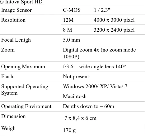
© Intova Sport HD
Image Sensor C-MOS 1 / 2.3''
Resolution 12M 4000 x 3000 pixel
8 M 3200 x 2400 pixel
Focal Lentgh 5.0 mm
Zoom Digital zoom 4x (no zoom mode
1080P)
Opening Maximum f/3.6 – wide angle lens 140°
Flash Not present
Supported Operating System
Windows 2000/ XP/ Vista/ 7
Macintosh
Operating Enviroment Depths down to – 60m
Dimension 7 x 8,4 x 6 cm
Weigh 170 g
Table 2. Main characteristics of Intova camera
© GoPro HERO 2
Image Sensor C-MOS 1 / 2.5”
Resolution 5M 2592 x 1944 pixel
Focal Lenght 5.0 mm
Zoom 1X
Opening Maximum F/ 2.8 fixed focal – wide angle
lens 170° - 8mm
Supported Operating
System Macintosh - Mac OS X 10.4.11 Windows Vista / 7 / 8
Operating Enviroment – 80m
Dimension 4,2 x 6 x 3 cm
Weight 167g
Table 3. Main characteristics of GoPro camera
4. IN SITU CAMERA CALIBRATION
The camera calibration has to be carried out in situ because of the extremely varying chemical and physical properties (salinity, temperature, density, etc.) of water, the medium the optical rays move across. In this analysis, it is assumed that within the very short period of the underwater phogrammetric survey these parameters, once determined, are invariant and can be used for the photogrammetric processing.
4.1 The frame for in situ camera calibration
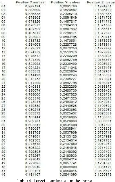
The frame is used for two main purposes: to provide the known points for the orientation of the photograms and to execute the cameras calibration. The reference frame is composed of PVC bars which form approximately the edges of a parallelepiped of the following size: 0.9 x 0.2 x 0.15 m. The weight is about 3 kg (see Figure 4 and 5 for different perspective views of the calibration bar). The known points (targets) are signalized with a rectangular target, 30 mm wide, with alternate black and with cross printed. All targets materialized on the frame have been numbered and measured and the coordinates, x, y and z, determined (Table 4) in a reference system fixed on the frame. The measures have been performed by scanning the frame with a triangulation-based laser scanner © Konika Minolta RANGE 7 and identifying the center of each target on the three-dimensional model at very high accuracy (Figure 6). The positions of the targets were determined with an accuracy lower than 0.1 mm. The PVC thermal dilatation coefficient is about 7 ppm for °C. The variation of temperature from the surface to the working area at a depth of 15 m was about 5°C (13 °C versus 18 °C) that produces a potential (maximum) length variation of about 35 micron for the 1 m length of the bar. This variation is less than the GSD and precision that are expected from the photogrammetric acquisition.
Figure 4. Calibration frame (I)
Figure 5. Calibration frame (II)
Figure 6. Calibration frame
Table 4. Target coordinates on the frame
4.2 3D Reconstruction on the frame model
Taking into account our choice to use the commercial software PhotoScan (©Agisoft), based on the Structure from Motion (SfM) approach (Ullman, 1979) and bundle adjustment, we have executed 12 photographs to portray the entire frame within each image. All acquisitions have been made at distance range of about 2 and 4 meters with a GSD (Ground Simple Distance) in the range about of 0.4 and 0.9 mm. Unfortunately, for the presence of a rocky block close to the frame (positioned near of the amphora, for subsequent photogrammetric survey), it was possible to photograph the frame mainly by a side only. The same procedure was performed for all three types of cameras. The SfM algorithm implemented by PhotoScan was used in this work to generate the dense point clouds of the frame. The reconstruction of objects by PhotoScan is a three-step process (Seitz, 2006). From a theoretical point of view, for a good reconstruction, at least two photographs representing a single point must be available. In this case, each point is represented in not less than 8 images. In the first step the alignment of the acquired images was performed. The SfM algorithm comes into play by the detection of image feature points (edges or others geometrical features) and reconstruction of their movement along the sequence of images. The SfM algorithm provides the basic geometry/structure of the scene, through the position of the numerous matched features, in addition to camera positions and internal calibration parameters. This is done in a local reference frame. In the second step a pixel-based dense stereo reconstruction was performed starting from the aligned dataset and sparse matching. After this step, fine topographic details reference coordinates as previously determinate in the frame-fixed reference system and was assigned a constant weight (marker accuracy in photoscan) of 40 micron for each collimated marker. At the end, the bundle adjustment procedure, based on the least squares methos, was launched and the calibration parameters determined by the model of Brown (Brown, 1971). The results could be retrieved by the final report provided and RMS (Root Means Square) on individual coordinates and the global RMS values inspected.
4.3 Determining camera calibration parameters
The calibration parameters determined for each of the three cameras are the following:
fx, fy: focal length measured in pixels cx, cy: principal point coordinates sk: skew transformation coefficient k1, k2, k3, k4: radial distortion coefficients p1, p2: tangential distortion coefficients.
The calibration procedure provided the results hereafter summarized. Table 5 and 6 reports results about the calibration parameters and bundle adjustment errors for the ©Canon Power Shot G12 camera.
Initial data (pix) Adjusted (pix)
fx 3000.32 4103.91
Table 6. Results of the bundle adjustment process for Canon camera
In Table 6 the flag means the point was included in the adjustment. As can be seen the maximum error is 0.939 mm The International Archives of the Photogrammetry, Remote Sensing and Spatial Information Sciences, Volume XL-5/W5, 2015
In Table 7 and 8 results from the calibration procedure and bundle adjustment errors are reported for the © Intova Sport HD.
Initial data (pix) Adjusted (pix)
fx 2778.13 4252.33
Table 8. Results of the bundle adjustment process for Intova camera
A maximum error of 9.551 mm can be detected from the table whereas the average total error is 11.330 mm. In Table 9 and 10 results from the calibration procedure and bundle adjustment errors are reported for the © GoPro HERO 2.
Initial data (pix) Adjusted (pix)
fx 3744.23 6573.37
Table 10. Results of the bundle adjustment process for GoPro camera
A maximum error of 38.564 mm and an average total error of
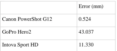
This paper aimed at comparing the performance of three cheap underwater cameras for metric applications. This evaluation was performed by analyzing the calibration parameters obtained under the same operating conditions. The shots were acquired at a sea depth of about 15 meters and a special calibration frame was used. By the application of a photogrammetric approach base on computer vision algorithms (SFM) and successive bundle adjustment, the calibration parameters of the three cameras were derived. These results are summarizing in Table 11 by using the total errors as a concise index.
Error (mm)
Canon PowerShot G12 0.524
GoPro Hero2 43.037
Intova Sport HD 11.330
Table 11. Comparison of total errors related to used cameras
On the basis of what we obtained during this test, the so-called commercial action-cameras type GoPro and Intova exhibited unfavourable characteristics for underwater metric purpose. This is likely due to the strong distortion caused by lenses with very small focal length. The use of such kind of cameras for similar applications requires different models for the calculation of calibration parameters. To the contrary, the Canon camera, produced a total error which is compatible with most of the scopes of the underwater photogrammetry. Distortions detected for such camera are in many cases acceptable and well represented by the Brown’s model and they are highlighted the behaviors to nonlinear optical projections of the cameras GoPro and Intova.
ACKNOWLEDGEMENTS
The authors thank Dr. Chiara Taglialatela (University of Bologna) for her contribution in the work of thesis and Dr. Isabella Toschi (FBK, Trento) for her valuable contribution.
REFERENCES
Brown D.C., 1971. Close-Range Camera Calibration. Photogr. Eng. 37: pp. 855-866
Capra A., 1992. Non-conventional system in underwater
photogrammetry. I.S.P.R.S. Archives vol. XXIX, Comm.V,
XVII I.S.P.R.S. International Congress, Washington, D.C. USA.
Capra A., 1994. Application of underwater photogrammetry for
the deformation control of submerged objects. ISPRS
Commission V (Melbourne), Vol.XXX, pp.16-22.
Caravalle A., Toffoletti I., 1997. Anfore antiche. Conoscere e
Identificarle. pp. 98-99 Istituto ricerche ecologiche ed
economiche Formello.
Drap P., Seinturie J., Long L., 2003. Archaeological 3D modelling using digital photogrammetry and expert system. The
case study of Etruscan amphorae. The Sixth International
Conference on Computer Graphics and Artificial Intelligence, May 2003, France.
Mancini F., Dubbini M., Gattelli M., Stecchi F., Fabbri S., Gabbianelli G., 2013. Using Unmanned Aerial Vehicles (UAV) for High-Resolution Reconstruction of Topography: The Structure from Motion Approach on Coastal Environments.
Remote Sensing, 5 (12), 6880-6898.
Remondino F., Fraser C., 2006. Digital camera calibration
methods: consideration and comparisons. International
Archives of Photogrammetry, Remote Sensing and Spatial Information Sciences, Vol.36(B5), Dresden, Germany
Seitz S.; Curless B.; Diebel J.; Scharstein D.; Szeliski R. A 2006. Comparison and Evaluation of Multi-View Stereo
Reconstruction Algorithms. In Proceedings of the 2006 IEEE
Computer Society Conference on Computer Vision and Pattern, Washington, DC, USA. pp. 519–528.
Troisi S., Menna F., Nocerino E., Remondino F., 2013. Il
rilievo della falla della M/N Costa Concordia. Proc. SIFET
Conference, Catania, Italy
Ullman S., 1979. The interpretation of structure from motion. Proc. R. Soc. Lond. B 1979, 203, pp. 405–426.