AUTOMATIC RECTIFICATION OF BUILDING FAÇADES
V. Tsironis, A. Tranou, A. Vythoulkas, A. Psalta, E. Petsa*, G. Karras
Laboratory of Photogrammetry, National Technical University of Athens, GR-15780 Athens, Greece
([email protected], [email protected], [email protected], [email protected], [email protected]) * Laboratory of Photogrammetry, Technological Educational Institute of Athens, GR-12243 Athens, Greece ([email protected])
Commission II
KEY WORDS: inter-image homography, rectification, fundamental matrix, SURF detector, Canny operator, Hough transform
ABSTRACT:
Focusing mainly on the case of (near-)planar building façades, a methodology for their automatic projective rectification is described and evaluated. It relies on a suitably configured, calibrated stereo pair of an object expected to contain a minimum of vertical and/or horizontal lines for the purposes of levelling. The SURF operator has been used for extracting and matching interest points. The co-planar points have been separated with two alternative methods. First, the fundamental matrix of the stereo pair, computed using ro-bust estimation, allows estimating the relative orientation of the calibrated pair; initial parameter values, if needed, may be estimated via the essential matrix. Intersection of valid points creates a 3D point set in model space, to which a plane is robustly fitted. Second, all initial point matches are directly used for robustly estimating the inter-image homography of the pair, thus directly selecting all image matches referring to coplanar points; initial values for the relative orientation parameters, if needed, may be estimated from a decomposition of the inter-image homography. Finally, all intersected coplanar model points yield the object-to-image homography to allow image rectification. The in-plane rotation required to finalize the transformation is found by assuming that rectified images contain sufficient straight linear segments to form a dominant pair of orthogonal directions which correspond to horizontality/verti-cality in 3D space. In our implementation, image edges from Canny detector are used in linear Hough Transform (HT) resulting in a 2D array (ρ, θ) with values equal to the sum of pixels belonging to the particular line. Quantization parameter values aim at absorbing possible slight deviations from collinearity due to thinning or uncorrected lens distortions. By first imposing a threshold expressing the minimum acceptable number of edge-characterized pixels, the resulting HT is accumulated along the ρ-dimension to give a single vector, whose values represent the number of lines of the particular direction. Since here the dominant pair of orthogonal directions has to be found, all vector values are added with their π/2-shifted counterpart. This function is then convolved with a 1D Gaussian function; the optimal angle of in-plane rotation is at the maximum value of the result. The described approach has been successfully evaluated with several building façades of varying morphology by assessing remaining line convergence (projectivity), skewness and deviations from horizontality/verticality. Mean estimated deviation from a metric result was 0°.2. Open questions are also discussed.
1. INTRODUCTION
Homography-based methods, in which images of a planar object are related to it and/or to each other (inter-image homography), have a wide spectrum of uses, including today’s important tasks such as segmentation of multi-planar scenes, camera positioning for visual navigation in indoor/outdoor scenes, and methods for vision-based robot control (Malis & Vargas, 2007; Montijano & Sagues, 2009; Zaheer et al., 2012). Due to their perspective na-ture, images also have to be actually rectified (mostly to ortho-gonal frontal views) in several single or stereo and multi-image applications, like single view metrology, photorealistic render-ing, image registration and mosaickrender-ing, mobile mapprender-ing, photo-texturing of 3D city models, and documentation of cultural heri-tage (Zhang & Kang, 2004; Geetha & Murali, 2013).
For the purposes of documentation, reconstruction and visuali-zation of urban scenes in particular, the standard 2D projective transformation always represents a core procedure of image rec-tification. Conventionally, photogrammetric applications in cul-tural heritage conservation are based on geodetically measured control points for establishing image registration into the object coordinate system; in this sense, for tasks such as digital rectifi-cation of building façades field work and manual measurement represent a disproportionately large part of the project. A grow-ing need for minimizgrow-ing human intervention has produced sug-gestions for automating planar rectification, particularly regard-ing realistic buildregard-ing façades. One possibility is to exploit
exist-ing 3D information for data fusion. In case laser scanning is also involved, extraction of control information from point clouds or their intensity images (Forkuo & King, 2004) can be considered. Pu & Vosselman (2009) combine information from terrestrial la-ser point clouds and conventional images into a semi-automatic approach for reconstructing building façades; planar objects are segmented from laser data, while extracted image lines help re-fine model edges. Such methods, including those involving seg-mentation of data from dense multi-view matching, clearly re-quire a significant amount of effort and several demanding prior steps (especially in view of “modest” tasks like façade rectifica-tions). On the other hand, single images have also been widely used, in this respect, to exploit purely the geometric information inscribed in automatically extracted vanishing points of known, typically orthogonal, directions of the plane (Liebowitz et al., 1999). In this context, Zaheer et al. (2012) made use of “angle regularity” in man-made scenes to rectify imagery of 3D planes to “fronto-parallel” views while searching for the homographies which maximize the number of right angles between projected line pairs. Yet, methods for removing projective deformation re-lying exclusively on line directions produce results sensitive to the number, length, accuracy and distribution of ‘extractable’ li-near segments; more important, they are rather limited to cases where at least two vanishing points can indeed be reliably local-ized (which is not always the case, mostly due to lack of suit-able number and distribution of lines on the object plane).
Focusing primarily on planar building façades, our contribution The International Archives of the Photogrammetry, Remote Sensing and Spatial Information Sciences, Volume XLII-2/W3, 2017
describes and evaluates a method for their automatic projective rectification using a stereo pair of the object. Given the camera parameters (and an object dimension or the length of the image basis), this simplest option of generating in a purely photogram-metric fashion 3D points in an arbitrarily oriented, albeit proper-ly scaled, model relies on the powerful geometry of relative ori-entation. Points thus established could, in principle, furnish the missing control for rectification: the model may be transformed into a suitable system based on inherent object characteristics, namely plane verticality and line verticality and/or horizontality. It is to note that lines are employed here simply for the purposes of in-plane rotation; thus, even one such line might (in theory at least) suffice. Results from manual point selection and measure-ment have indicated that, for stereo pairs of suitable configura-tions, the required accuracy can indeed be comfortably obtained (Karras, 2005). Here, this approach has been fully automated.
As described in the following sections, a stereo pair which in-cludes the planar object is taken. Necessary assumptions (which at the same time point to the limitations of the approach) are:
• The scene is recorded with a fully calibrated camera (in-cluding lens distortions). This can be done beforehand by freely available tools based on chessboards, with the use of test fields, or via appropriately configured multi-image bundle adjustment. • The stereo pair geometry should represent a “reasonable” base-to-distance ratio; thus, a (mild) convergence of image axes is recommended. Although excessive perspective distortions be-tween the images should be avoided to ensure that point match-ing will not run into difficulty, angles of relative convergence in the range 10º-45º have been used here. Furthermore, one of the images should preferably be near-frontal, i.e. suitable for rectifi-cation. Image scale, i.e. pixel size in 3D space (mean “groundel” size), must comply with the scale of rectification – if required.
• The planar object of interest should occupy a substantial part of the stereo pair, to guarantee feasibility of geometric seg-mentation of the plane of interest.
• It is assumed that the façade includes at least a few lines which are predominantly horizontal and/or vertical.
On such images, an operator for feature extraction and matching is used. Outliers are removed by robustly estimating the tric relation which constrains the image pair; alternative geome-trical models are the fundamental matrix and inter-image homo-graphy. The M-estimator SAmple and Consensus (MSAC) robust estimator (Torr & Murray, 1997), a variant of RANSAC, as im-plemented in Matlab has been applied. This will allow selection and reconstruction of coplanar points; next, the model plane is rendered vertical for images to be rectified (Section 2). The do-minant pair of orthogonal directions is, subsequently, identified on the transformed images via an adapted Hough transform; this supplies the in-plane rotation required to conclude image trans-formation (Section 3). The performance of the method is evalu-ated by considering relations among rectified lines (Section 4).
2. HOMOGRAPHY AND IMAGE RECTIFICATION
The SURF operator (Bay et al., 2008) has been applied here for extracting and matching points across the image pair. Despite considerable perspective differences within the pairs, SURF has functioned quite efficiently; of course, the Affine SIFT detector (Morel & Yu, 2009) could also have been used instead.
2.1 Identifying coplanar points via the fundamental matrix
One way to proceed is by robustly estimating the fundamental
matrix F of the image pair; the MSAC robust estimator has been employed for filtering out matched points which violate the epi-polar constraint. Next, the relative orientation of the image pair is found iteratively. For the type of image configurations treated here, initial parameter values set to zero are generally adequate (if needed, approximations can be estimated linearly through the essential matrix E of the pair). All valid points are subsequently intersected to generate a 3D point set in model space. If image pairs have indeed been taken as indicated above, the majority of valid points should belong to the object plane. To all 3D points a plane is fitted robustly to separate the planar object from irre-levant points of the scene. The threshold in 3D space for elimi-nating off-plane points is fixed according to the required scale. Outcome is matches of all valid coplanar 3D model points with their images: (x,y,z)↔(i,j).
2.2 Identifying coplanar points via inter-image homography
In cases of planar (or near-planar) scenes the F matrix cannot be (stably) calculated. It is self-evident that such an ill-conditioned case may well arise in the context of this work. Homography is the suitable model for similar failures of the epipolar constraint (Wadenbäck & Heyden, 2013). All initial SURF matches are thus directly employed for robustly estimating the inter-image
homo-graphy matrix HI, which defines the mapping relation between images intermediated by recording the same 2D surface. Among all putative matches those referring to coplanar points are, thus, directly selected. As here both erroneously matched points (out-liers) and off-plane points are to be discarded in one step, a sig-nificant part of the putative correspondences should refer to the plane of interest. If the algorithm fails, one may first use F for eliminating actual outliers; however, in our tests the inter-image homography matrices were always recovered with no problem. The relative orientation of the pair is then determined by relying purely on the coplanar matches. This might cause the bundles of image rays to “narrow”, yet the relative orientation parameter values will be “focused” on the actual region of interest. If ini-tialization for the rotation and translation parameters would ap-pear as necessary, initial values may be estimated from a decom-position of the inter-image homography matrix HI (Ma et al., 2003; Malis & Vargas, 2007). Finally, the intersected coplanar 3D model points produce, here again, the plane-to-image corres-pondences (x,y,z)↔(i,j).
2.3 Restoring plane verticality and image rectification
Coplanar model points (x, y, z), identified in the preceding step, define a tilted plane (typically expressed in the system of the left image), which can be fitted as:
z = ax + by + c (1)
This plane is assumed to represent the (vertical) planar building façade; hence its tilt has to be removed for rectification. System x(xyz) is transformed to a system X(XYZ) = RTx, such that the plane equation becomes Z = constant. If R = RΦRΩ is the
typi-cal rotation matrix as used in photogrammetry, rotation angles Ω and Φ (about the x-axis and y-axis, respectively) are extract-ed from the coefficients of the fittextract-ed plane as:
Φ = arctan(a) Ω = −arctan(bcosΦ) (2)
In this system, point correspondences (X,Y)↔(i,j) allow estima-ting the two plane-to-image homography matrices H, and rectify the images. The new images are, in principle, free of both
pro-jective and affine distortions, i.e. correct up to a similarity
trans-formation. Figs. 1 and 2 give examples for the preceding steps. The International Archives of the Photogrammetry, Remote Sensing and Spatial Information Sciences, Volume XLII-2/W3, 2017
Figure 1. Top row: initial image pair (image axes convergence of 16º). Second row: initial SURF matches (2189). Third row:
filtered coplanar points (829). Bottom row: automatically rectified images.
Figure 2. Top row: initial image pair (image axes convergence of 40º). Bottom row: automatically rectified images.
2.4 The question of multi-planar façades
The general issue of multi-planar scenes falls outside the scope of this work. As seen in Fig. 2, however, a ‘planar’ façade might well consist of more than one (parallel) planes. In similar cases, plane extraction is conditioned by the tolerance defining inliers during a robust estimation of plane-fitting (this threshold is a distance in 3D model space if the F matrix is employed, and a distance in pixels for the inter-image homography). In Fig. 3 the
matched coplanar points on the dominant and the “next-domi-nant” planes of this façade are seen (the doors apparently repre-sent further parallel planes).
If in such cases a large tolerance is used for inlier acceptance in order to find the overall best-fitting plane, the outcome will be in all probability a plane not parallel to the façade. This will in-duce projective or affine distortions in the rectification. It would therefore be safer to keep to strict thresholds and perform recti-fication adapted to the “dominant” plane (as in the case of Fig. 2); in such instances, planes parallel to it will of course be recti-fied with small errors in scale and translation.
Figure 3. Top row: initial SURF matches (1718). Middle row: filtered points of the dominant plane (602). Bottom row: filtered
points of the next-dominant plane (323).
3. IN-PLANE ROTATION OF RECTIFIED IMAGES
As in the context of this work translation/scaling are irrelevant, the sole remaining transformation towards a metric result is an in-plane rotation. This may be estimated under the plausible as-sumption that certain straight linear features will indeed appear on the façade and, predominantly, indicate the horizontal and/or vertical directions. Since on the rectified image parallelism and orthogonality of coplanar object lines have already been restor-ed, identification of the dominant pair of orthogonal directions on this image directly supplies the required angle of rotation.
To tackle this problem, the intuitive algorithm Rotation Estima-tion using Hough Transform (REHT) has been developed. Short-ly, it consists of three main steps: edge detection; Hough trans-form; and, finally, estimation of in-plane rotation angle K. Edge detection is performed using the well-known Canny edge detec-tor, mainly because of its ability to produce “thin” and reliable edges. In this step, an edge threshold parameter stands as upper threshold of the Canny extractor. The default value for this pa-rameter was set at 0.4 in our tests. One example for edges thus detected are presented in Fig. 4 (left image of the pair of Fig. 1). The International Archives of the Photogrammetry, Remote Sensing and Spatial Information Sciences, Volume XLII-2/W3, 2017
Figure 4. Outcome of the Canny edge detector.
Next step is Hough Transform (HT) itself. The Standard Linear Hough Transform is used with 2 parameters: angle quantization step (default: 0.01º); bin spacing along the polar distance axis of the HT diagram (default: 5 pixels). It is to note that the first pa-rameter is generally given small angular values and has a strong effect on the overall accuracy of the method, while the second refers to the thickness of each line in the HT diagram. Taking in-to account the fact that remaining radial disin-tortion might be pre-sent and, also, the thinning process of edge detection, relatively large integer values (3-10) should be assigned to this parameter.
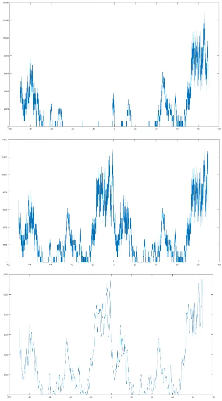
The HT diagram is then thresholded; the thresholding value (T) is set using a specific (parameter-controlled) convex combina-tion of the maximum and median values of the non-zero subset of the HT diagram. Generally, given a typical distribution of va-lues in the HT diagram, T-values should be around a 70%-30% median-max weighted average (corresponding to value 0.7 for the threshold-controlling parameter). Thresholding is indispens-able as the goal is to suitably accumulate the HT diagram along the polar distance axis (without thresholding such an integration would clearly produce a constant valued vector). Thus, by using the thresholded HT,a vector f (function of angle ϑ, which deno-tes line inclination) is created; for a given ϑ-angle, the f-value essentially represents the number of ϑ-oriented lines which meet more than T “edge-characterized” pixels (T-condition). Further-more, due to the assumed existence of a dominant pair of ortho-gonal directions in the image, a new vector g is created as the concatenation of the aforementioned vector f and a 90º-shifted version of it. This vector g(ϑ) actually represents the number of lines with direction angles ϑ or ϑ+π/2 which meet the T-condi-tion. Resulting vector g is symmetric for angle offsets of 90o, which leads to a K-angle estimation range within ±45o (in phy-sical sense, as horizontal direction the one with the smaller ϑ -angle is assumed). However, such an approach might be poten-tially problematic, since there is no tolerance in both verticality and horizontality errors. To compensate for this, function g is convolved using a 1D Gaussian function, its standard deviation being a user-controlled parameter (default: 1º); thus, a weighted averaging operation is applied to each element of vector/func-tion g. Last, as optimal Κ-angle the argmax of convolved vector
g is chosen. Fig. 5 illustrates the steps outlined above; Fig. 6
gi-ves an example of in-plane rotation adjustment.
The REHT algorithm has been extensively tested with a variety of images of known rotation angle and, in the large majority of cases, managed to recover them with deviations of a few hun-dredths of the degree using the default parameter values. Yet, it is to underline that in certain cases some extra fine-tuning of the parameters is needed in order to obtain valid results. This said,
given the prototype nature of this first implementation, it can be observed that using the default parameter values it has returned correct angles in ¾ of the cases, while with proper selection of parameters values it successfully provided (within tenths of a degree at most) the correct angle in all cases of our tests.
Figure 5. Estimation of in-plane rotation. Top: vector f (accu-mulation of thresholded HT diagram). Middle: vector g (conca-tenation of f and its 90º-shifted version; note the 90o symmetry). Bottom: convolved vector; its argmax gives the optimal
estima-tion of the in-plane angle of rotaestima-tion (in this case it is -1º.02).
Figure 6. Rectified (cf. Fig.2) and rotated image.
Finally, it is pointed out that cases can occur where the assumed dominance of horizontal and/or vertical façade lines is not valid (roof edges, for instance, might mislead the algorithm). The pre-The International Archives of the Photogrammetry, Remote Sensing and Spatial Information Sciences, Volume XLII-2/W3, 2017
sented approach is general. Nonetheless, for the purposes of the particular application addressed here the values of in-plane rota-tions are expected to be small as they essentially reflect the roll-angle of the left camera (the plane is reconstructed in its system) with respect to the actual façade. Such rotations are, generally, small (in the tests of the next section they did not exceed 3º). In such extreme cases, therefore, the acceptable angles could be li-mited within a short interval around 0º (±5º or, at most, ±10º), adding further robustness to the methodology.
4. EXPERIMENTAL EVALUATION
Besides the two image pairs already shown in Figs. 1 and 2, our approach has also been applied to the four pairs of Figs. 7-10. The resulting six rectifications have been evaluated chiefly re-garding the restoration of line directions. The issue of non-uni-form image scale has not been examined (affine scale is mainly related to errors of the interior orientation parameters).
Figure 7. Rectified and rotated left image of the above pair (image axes convergence of 32º).
Figure 8. Rectified and rotated left image of the above pair (image axes convergence of 44º).
As many as possible horizontal and vertical lines of the façades were manually measured on the final rectified images and fitted (with a mean standard error 0.06º for their estimated angles of inclination). For the horizontal lines in each image the mean mH and standard deviation σH of the angles they formed with the x-axis were computed; the respective values for the angles formed by vertical lines with the y-axis were mV and σV. Values σH, σV are an indication for the deviations from parallelism in the two directions; their RMS value σP might be regarded, in a way, as a
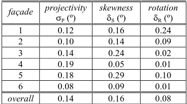
measure for the overall projective distortions which survived re-ctification. On the other hand, angle δS = mH–mV indicates the mean deviation from orthogonality, i.e. it is a measure for the presence of skewness in the images. Finally, the mean value δR of mH and mV may be regarded as an angle expressing the mean deviation of lines from horizontality and verticality, i.e. the un-corrected in-plane rotation (clearly, this value δR of the remain-ing rotation is affected by skewness). On the other hand, the re-sults also depend on whether actual object lines indeed stand in agreement with their assumed directions. Notwithstanding such considerations, these measures are considered here as conveying a good idea about the performance of the presented approach. The results for the six façades are given in Table 1.
façade projectivity
σP (º)
skewness
δS (º)
rotation
δR (º)
1 0.12 0.16 0.24
2 0.10 0.14 0.09
3 0.14 0.24 0.02
4 0.19 0.05 0.01
5 0.18 0.29 0.10
6 0.08 0.09 0.01
overall 0.14 0.16 0.08
Table 1. Rectification results for the six façades.
Figure 9. Final rotated images of the above pair (image axes convergence of 10º).
Figure 10. Final rotated images of the above pair (image axes convergence of 25º).
It is seen that mean angular errors of projectivity (line conver-gence), skewness and in-plane rotation may be reflected in va-lues around 0.2º. This is equivalent to a relative shift of 3-4 cm, for instance, between the endpoints of a 10 m long linear seg-ment. This accuracy satisfies several practical applications.
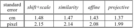
Finally, 12 natural check points (of estimated precision ±1 cm) were available for the façade of Fig. 10. Rectification has been evaluated against these via 2D transformations. In Table 2 one sees that only very slight improvements emerge for higher trans-formations. This implies that systematic deformations can be re-garded here as negligible. A significant part of the error might, of course, be attributed to the check points themselves.
standard
error shift+scale similarity affine projective
cm 1.48 1.47 1.43 1.37
pixel 2.15 2.14 2.08 1.99
Table 2. Standard errors of 2D transformations.
5. CONCLUDING REMARKS
A methodology has been presented and evaluated for automati-cally rectifying typical near-planar building façades, containing at least a minimum of horizontal and/or vertical straight lines. Among point matches produced by a standard point extractor on a calibrated stereo pair of suitable geometry, those referring to the planar object are selected, using the geometric constraints of either epipolar geometry or inter-image homography. The image points thus matched to intersected coplanar façade points allow image rectification. The remaining in-plane rotation is estimated by identifying the dominant pair of orthogonal directions on the façade. This succeeds by suitably aggregating, thresholding and processing the result of linear Hough transform. Results from several objects of different morphology have indicated that an expected realistic accuracy of this approach could be about 0º.2 as regards assumed line directions in object space.
Of course, the approach is inherently limited to objects allowing reliable automatic identification of in-plane rotation; besides, it strongly depends on the configuration of the stereo pair. Interior camera orientation parameters need to be reliably known. In our case, camera data had been obtained via self-calibrating bundle adjustments of simple image strips of 5-7 images (i.e. they suf-fered from significant correlations with exterior orientation pa-rameters). On the other hand, it would be necessary to adjust the distribution of matched points in order to ensure a possibly even participation of all object parts. The algorithm for recovering in-plane rotation is of course also open to elaboration towards both improving its accuracy, if possible, and providing means for re-cognizing basic façade patterns (such as windows) which define standard known directions. Identification of the limits of a parti-cular building façade itself is obviously a further open question. Such are some possible topics of future research.
REFERENCES
Bay H., Ess A., Tuytelaars T., van Gool, L., 2008. Speeded-up robust features (SURF). Computer Vision & Image
Understand-ing, 110, pp. 346-359.
Forkuo, E. K., King, B., 2004. Registration of photogrammetric imagery and laser scanner point clouds. ASPRS Annual Confe-rence, Denver, Colorado.
Geetha K.A., Murali S., 2013. Automatic rectification of per-spective distortion from a single image using plane homogra-phy. International Journal on Computational Sciences &
Appli-cations, 3(5), pp. 47-58.
Karras G., 2005. Is it realistic to generate control points from a stereo pair? XX CIPA International Symposium, pp. 399-402.
Liebowitz, D., Criminisi, A., Zisserman, A., 1999. Creating ar-chitectural models from images.Computer Graphics Forum, 18,
pp. 39-50.
Ma Y., Soatto S., Kosecka J., Sastry S.S., 2003. An Invitation to
3-D Vision: From Images to Geometric Models. Springer.
Malis E., Vargas M., 2007. Deeper Understanding of the
Ho-mography Decomposition for Vision-Based Control. Research
Report RR-6303, INRIA, pp.90.
Montijano E., Sagues C., 2009. Fast pose estimation for visual navigation using homographies. Proc. IEEE/RSJ International Conference on Intelligent Robots and Systems, St. Louis, USA, pp. 2704-2709.
Morel J., Yu G., 2009. ASIFT: A new framework for fully affine invariant image comparison.SIAM Journal on Imaging Sciences,
2, pp. 438-446.
Pu S., Vosselman G., 2009. Building façade reconstruction by fusing terrestrial laser points and images. Sensors, 9, pp. 4525-4542.
Torr P.H.S., Murray D.W., 1997. The development and compa-rison of robust methods for estimating the fundamental matrix.
International Journal of Computer Vision, 24(3), pp. 271-300.
Wadenbäck M., Heyden A., 2013. Planar motion and hand-eye calibration using inter-image homographies from a planar scene.
8thInternationalJointConferenceonComputer Vision, Imaging
andComputerGraphicsTheory& Applications, SciTePress, pp.
164-168.
Zaheer A., Rashid M., Khan S., 2012. Shape from angle regu-larity. European Conference on Computer Vision (ECCV), Part VI, LNCS 7577, Springer, pp. 1-14, 2012.
Zhang, Z., Kang, Z, 2004. The rendering of building texture from land-based video. International Archives of
Photogram-metry and Remote Sensing, XXXV(B3), pp. 732-737. The International Archives of the Photogrammetry, Remote Sensing and Spatial Information Sciences, Volume XLII-2/W3, 2017