LONG
-
TERM TRACKING OF A SPECIFIC VEHICLE USING AIRBORNE OPTICAL CAMERA SYSTEMSF. Kurz, D. Rosenbaum, H. Runge, D. Cerra, G. Mattyus, P. Reinartz
German Aerospace Center, 82234 Wessling, Germany - (franz.kurz, dominik.rosenbaum, hartmut.runge, daniele.cerra, gellert.mattyus, peter.reinartz)@dlr.de
Commission II, WG II/8
KEY WORDS: vehicle tracking, airborne camera system, macroscopic traffic model
ABSTRACT:
In this paper we present two low cost, airborne sensor systems capable of long-term vehicle tracking. Based on the properties of the sensors, a method for automatic real-time, long-term tracking of individual vehicles is presented. This combines the detection and tracking of the vehicle in low frame rate image sequences and applies the lagged Cell Transmission Model (CTM) to handle longer tracking outages occurring in complex traffic situations, e.g. tunnels. The CTM model uses the traffic conditions in the proximities of the target vehicle and estimates its motion to predict the position where it reappears.
The method is validated on an airborne image sequence acquired from a helicopter. Several reference vehicles are tracked within a range of 500m in a complex urban traffic situation. An artificial tracking outage of 240m is simulated, which is handled by the CTM. For this, all the vehicles in the close proximity are automatically detected and tracked to estimate the basic density-flow relations of the CTM model. Finally, the real and simulated trajectories of the reference vehicles in the outage are compared showing good correspondence also in congested traffic situations.
1. INTRODUCTION
The automatic real-time long-term tracking of vehicles using airborne optical camera systems can be relevant in a wide range of applications, e.g. transport monitoring, car fleet management, VIP vehicle monitoring during mass events or automotive industry applications. An optical camera system combining a large FOV with a long focal length is able to show both a larger context around the tracked vehicle and a high resolution image of the target. This enables more robust tracking, particularly in the case of occlusions, e.g. when the object drives under a bridge or behind a high building. In the first part of this paper, two low cost sensor systems for vehicle tracking are presented and compared with reference sensor systems which are mainly installed on military and BOS helicopters. In the second part of this paper, a method for automatic real-time long-term tracking of a specific vehicle is presented, which combines the detection and tracking of vehicles in low frame rate image sequences (Szottka, 2011; Leitloff, 2014) and the lagged cell transmission model CTM (Daganzo, 1999) to bypass longer tracking outages in complex traffic situations. This method is demonstrated on an airborne dataset acquired on 16th October 2014 over Munich/Germany.
2. SENSOR SYSTEMS FOR VEHICLE TRACKING
Two in-house developed, real-time optical camera systems were developed for the automatic tracking of specific vehicles, the CHICAGO system on a motorized glider (Runge, 2012) and the 4k system on a helicopter (Kurz, 2014). Both sensors consist of three frame cameras, which are aligned in different viewing directions. A fully real-time image processing chain on both platforms delivers the results to a ground station via a high capacity data link. For the real-time processing and the distribution of airborne images, an on-board processing chain including data transfer from airplane to ground is installed. The on-board system consists of the optical sensors, the GPS/IMU, the processing units, and a C-band microwave data link with a downlink capacity of up to 12Mbit/s with 40MHz bandwidth. The maximum frame rate of the cameras is reduced to
0.2-1.0 fps, to keep the data amount for real-time long-term tracking within acceptable levels. This limitation requires a low-frame rate tracking algorithm, which consists of a NCC or template based matching in combination with a motion model and a model-update strategy (Szottka, 2011).
The flight patterns differ between the sensor systems due to the flight properties of the motor glider and the helicopter. The helicopter can hoover and accelerate, whereas the glider is able to fly only in a determined speed range. Thus, the platform properties and the instructions given to the pilot must be accounted for, as a simple fly-by-sight to follow a specific vehicle is often not possible for the pilots.
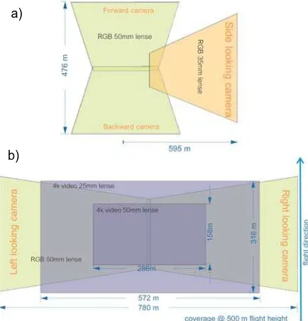
Figure 1: Footprints of a) CHICAGO and b) 4k sensor system based on a flight height of 500m a.g.
a)
b)
In figure 1, the viewing geometry of the 4k and CHICAGO sensor system is illustrated, showing the coverage in flight direction of 476m resp. 316m from the CHICAGO resp. 4k system. The tracked vehicle must be in this range, otherwise the vehicle is lost. The pilots must therefore react very fast, if the vehicle changes speed or makes turns. The helicopter can start to hoover if the vehicle stops, whereas the glider can start to circle around the position of the vehicle.
Table 1 lists the pro and cons of the two proprietary sensor systems in comparison to a reference sensor system. The main difference is the missing directional view of the proprietary sensors, which shifts the tracking task partly from the sensor operator to the pilots. On the other hands, the proprietary sensors provide a wide IFOV combined with a high resolution, which allows the monitoring of the traffic context and allows to a certain degree a de-synchronized tracking between flying platform and vehicle.
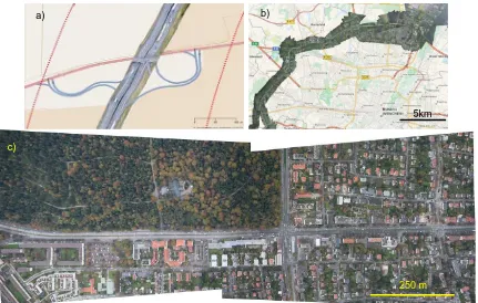
Figure 2 shows image examples from the three discussed sensor systems. A map section from the FLIR Ultraforce II (figure 2a) shows the small IFOV in comparison to the 4k sensor system. Figure 2b shows the footprints of the CHICAGO sensor system.
The main advantage here is the ability to circle around one position, whereas figure 2c reports a map section of the 4k system, in which the helicopter is hoovering for a long-time.
Reference sensor,
- flight instructions for pilots required
Table 1: Potential of 4k and CHICAGO sensor system for long-term vehicle tracking in comparison with a reference
sensor system
Figure 2: Map section from different sensors and platforms. a) Map section acquired with the FLIR Ultraforce II sensor system on 16th January 2015 south of Darmstadt/Germany (flight height 350m a.g.). Red dotted lines show the coverage of the 4k sensor system from the same flight height; b) Map section acquired with the CHICAGO sensor system in the north of Munich/Germany
on 19th May 2012 (flight height 600m a.g.); c) Map section acquired with the 4k sensor system on 16th October 2014 in Munich (flight height 1000m a.g.)
3. TRAFFIC MODEL FOR ROBUST VEHICLE TRACKING
The cell-transmission model CTM (Daganzo, 1994) can be used to predict trajectories in complex traffic situations for a specific vehicle in occluded areas, such as tunnels or roads
vegetation. For this purpose, traffic states are categorised into non-impeded or congested states at the entrance and possible exit of occluded areas. Then, the velocity of the tracked vehicle within the occluded area will be derived from the density-flow relations, simulated iteratively based on the CTM model.
250 m c)
b) a)
5km
specific vehicle at a certain position, where the automatic image-based tracking can continue.
The CTM simulates traffic flows in a discrete time interval with continuum flow models. The general configuration of the model is to divide a road into homogeneous sections of length L and to transmit all vehicles in a cell to the next for a certain time step t, unless flows are influenced by congestion from downstream. However, in most cases the speed is influenced by the amount of vehicles in the sections. Thus, the CTM model is extended to the lagged CTM (Daganzo 1999), which includes the most common density-flow relations. In the lagged CTM, the flow-density relation is generated from an actual data set.
The change in the traffic density ∆ of cell i depends on the actual density and the incoming and outgoing traffic flow (equ. 1).
∆ ∆ ∆ (1)
According to the lagged CTM, the mean speed ∆ in cell i depends on the actual density and a function f, which is based on a fuzzy logic to classify traffic states in congested and free flow (equ. 2).
∆ , (2)
Fuzzy logic is used in a first step to replace absolute values for density and speed with simple categories, because in reality it is hard to find a boundary, beyond which traffic is congested or not. In this logic, the traffic states of the cells will depend not only on the mean momentary speed and density inside the cell, but also on the states of adjacent cells from upstream and downstream (table 2).
Traffic Table 2: Fuzzy logic to identify traffic state at the cell i in the
time step t
Based on the classified traffic state within a cell, the empirical function f calculates then the speed based on the traffic density (equ. 3).
/ (3)
The empirical parameters a, b and c are estimated from the actual data set for different free flowing and impeded traffic situations.
Automatically extracted traffic parameters from image sequences are used for the estimation of empirical parameters in equation 3. The following steps are performed for each image pair (Leitloff, 214):
1. Orthorectification of images
2. Use of a road database to define the search areas 3. Detection of vehicles
4. Tracking of vehicles
5. Outlier detection, plausibility tests
6. Assignment of tracked vehicles to road segments 7. Define cells and calculate mean speed and traffic
density
8. Estimate empirical parameters
4. EXPERIMENTS
In this chapter, the proposed method will be validated with an airborne image sequence acquired on 16th October 2014 from a helicopter. The map section in figure 2c was acquired with 150 left and right looking images with 0.66 fps from 1000 m above ground in the center of Munich/Germany. All images are orthorectified and one main traffic roads with three lanes was selected for the experiment.
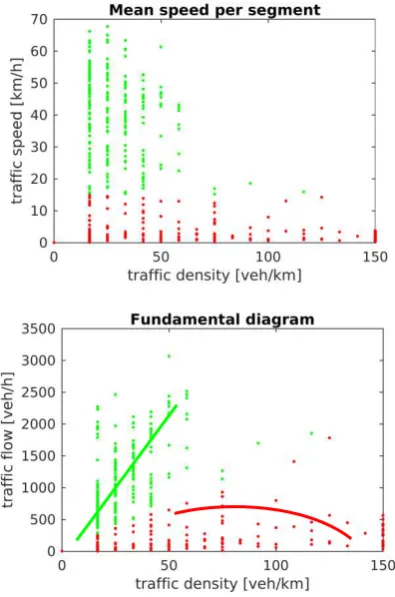
Figure 3: Automatically extracted traffic densities vs. mean traffic speed and traffic flow plotted for each segment. The green and red colour indicates free flow and congested traffic
states. The lines show the averaged trend for the two traffic states.
Figure 3 shows the relation between traffic density, traffic speed, and traffic flow based on the automatically extracted traffic parameters. The fundamental diagram shows a discontinuity between the free and congested traffic states. Finally, the traffic density of 50 veh/km was chosen as fuzzy limit to separate between free and congested traffic state. The CTM model was then applied to a road section with a length of 240 m, containing six cells with a length of 40 m. This road section simulates a tracking outage caused by a tunnel or by occlusions. Three reference vehicles were randomly selected and tracked by a simple NCC matching algorithm; subsequently, the time needed by the reference vehicles to travel through the six occluded cells was determined. Then, the CTM model was applied to calculate the time needed from the reference vehicles to travel through the six cells.
The results of the CTM simulation are illustrated in figure 4, including all processing steps shown for every forth image in
the sequence. All automatically extracted vehicles are plotted with a coloured dot representing the vehicle speed in column a). The density and speed was then determined for each cell in column b). The density and speed of the first (exit of outage) and eighth column (entrance to outage) was then taken as input to start the CTM simulation (column c). The travel times of the three reference vehicles (cyan, yellow and green dots) of the simulation c) can be directly compared with the ground in b). The CTM model improves the travel time estimation for the dense traffic states (cyan and green vehicle) compared to a simple linear estimation. In the free flowing case (yellow vehicle), the CTM model calculation is correct, but a simple linear estimation seems to be sufficient, too. Anyway, the error in the travel time estimation for the dense traffic states is still quite high, around 5s (cyan vehicle) and 12s (green vehicle).
Figure 4: 4k image sequences showing the traffic flow from right to left a) the results of the automatic vehicle detection and tracking; b) the calculated traffic density and real travel times of three reference vehicles (cyan, yellow, green dots); c) the results of the traffic density and travel time estimation to bypass a simulated tracking outage for the three reference vehicles
based on the CTM model.
5. CONCLUSIONS
In the first part of this paper, different low cost proprietary sensor systems for vehicle tracking are presented and compared with reference sensor systems which are mainly installed on military and BOS helicopters, along with a discussion on the advantages and drawbacks of the different sensor systems. The main disadvantage of the proprietary sensors is the missing directional view, whereas the wide IFOV allows the monitoring of the traffic context and environment around the tracked vehicle.
In the second part of this paper, a method for automatic real-time long-term tracking of a specific vehicle is presented, which combines the detection and tracking of vehicles in low frame rate image sequences and the lagged cell transmission model CTM to bypass longer tracking outages in complex traffic situations. The experiment shows to a certain degree the improvement in the travel time estimation in occluded areas, such as tunnels, in particular for dense traffic states.
REFERENCES:
Daganzo, C. F., 1994. The cell transmission model: A dynamic representation of highway traffic consistent with the hydrodynamic theory. In: Transportation Research Part B, 28 (4), pp. 269-287.
Daganzo, C. F., 1999. The lagged cell-transmission model. In: Proceedings of the 14. International Symposium on Transportation and Traffic Theory, Jerusalem, Israel, pp. 147-71.
Kurz, F., Rosenbaum, D., Meynberg, O., Mattyus, G., Reinartz, P. 2014. Performance of a real-time sensor and processing system on a helicopter. In: ISPRS Archives, Seiten 189-193. ISPRS Archive. Pecora 19 Symposium in conjunction with the Joint Symposium of ISPRS Technical Commission I and IAG Commission 4, 17.-20. Nov. 2014, Denver, USA. ISSN 2194-9034
Leitloff, J., Rosenbaum, D., Kurz, F., Meynberg, O., Reinartz, P. 2014. In: Remote Sensing, 6 (11), Seiten 11315-11341. MDPI AG. ISSN 2072-4292
Runge, H., 2012. CHICAGO - An Airborne Observation System for Security Applications. In: Seren2 Security International Partnering Event, 25. Sept. 2012, Essen.
Szottka, I., Butenuth, M. 2011. Tracking multiple vehicles in airborne image sequences of complex urban environments. In: Urban Remote Sensing Event (JURSE), 2011 Joint, vol., no., pp.13-16, 11-13 April 2011